
Subscribe to Our Youtube Channel
Related Manuals for Ditel MICRA-D


Summary of Contents for Ditel MICRA-D
- Page 1 INSTRUCTIONS MANUAL MICRA-D COUNTER - TOTALIZER TACHOMETER - TOTALIZER FREQUENCY METER CHRONOMETER...
-
Page 2: Table Of Contents
INDEX 1. OVERVIEW ..............................4 1.1 Introduction to model Micra D ........................4 2. GETTING STARTED? ............................ 7 2.1 Dimensions and mounting ........................8 2.2 Programming guide ..........................9 2.3 Power Supply. Connectors ........................11 2.4 Description functions keys and LED's in programming mode and mode RUN ..........12 2.5 Input signal (CN2) Connection ....................... - Page 3 6. LOGIC FUNCTIONS ..........................32 6.1 Programmable functions table ......................... 33 6.1.1 Logic functions diagram ........................ 33 6.2 Program of functions ..........................34 7. PROGRAM PARAMETERS AND KEYBOARD FUNCTIONS LOCK-OUT ............. 35 7.1 Security menu diagram .......................... 36 8. RESTORATION TO FACTORY CONFIGURATION ................... 38 9.
-
Page 4: Overview
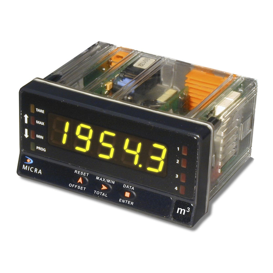
1.1 Introduction to model Micra D The MICRA-D model from the KOSMOS SERIE is a five-digit digital instrument with 2 programmable inputs that accept signals from a variety of standard sensors and pulse generators. Can be configured to work as:... - Page 5 PROCESS COUNTER • Alternating display of 4 digits high order part and 4 counter, DOWN counter bidirectional digits low order part of the value with corresponding UP/DOWN counter indication H and L. In UP/ DOWN mode it can be programmed to •...
- Page 6 TACHOMETER WITH DIRECTION INDICATION 13 programmable logic functions operated at the • The MICRA-D senses direction of rotation and rear connector enhance the functionality of the indicates polarity of the signal by means of LED’s meter allow controlling basic operations represented by up and down arrows.
-
Page 7: Getting Started
Digital panel meter MICRA-D. Accessories for panel mounting (sealing gasket and fixing clips). Accessories for wiring connections (plug-in terminal block connectors with a fingertip key). Wiring label stuck to the MICRA-D case. 4 set of labels with engineering units. Check the packing contents. -
Page 8: Dimensions And Mounting
The figure below shows the locations of the different output options available. The 2RE, 4RE, 4OP y 4OPP options are alternative and only one of them can be installed in the M1 connector. The RS2 y RS4 options are also alternative and only one of them can be installed in the M2 connector. The NMA or NMV are also alternative and only one of them can be installed in the M3 connector. -
Page 9: Programming Guide
2.2 Programming guide How to get into programming mode? First, plug the instrument to the corresponding supply, automatically a display test will be done and after that the software version will be shown then the instrument will go to work mode. Second, press the key to enter into the programming mode, the indication "-Pro-"... - Page 10 Accessing to programmed parameters Thanks to the tree structure, the programming routines allow to access to one parameter and modify it without passing through the whole list of parameters. To advance through programming The progress through the programming routines is done by pressing key.
-
Page 11: Power Supply. Connectors
WIRING and POWER SUPPLY RANGE MICRA-D 85 V – 265 V AC 50/ 60 Hz or 100 – 300 V DC MICRA-D6 CONNECTORS 22 –... -
Page 12: Description Functions Keys And Led's In Programming Mode And Mode Run
2.4 Functions keys and LED's description in programming mode and RUN mode TARE PROG RESET MAX/MIN DATA OFFSET ENTER TOTAL Function in programming mode Function in RUN mode - to step forward in programming menu - to enter programming menu or to visualize DATA DATA - to validate programmed values... -
Page 13: Input Signal (Cn2) Connection
2.5 – Input signal (CN2) Connection Refer to connection recommendations on page 11 Instrument´s rear view PIN 1 = No Connection PIN 2 = (+) 18 V Excitation PIN 3 = (+) 8,2 V Excitation Namur sensors PIN 4 = ( - ) Common excitation / input PIN 5 = Signal B input PIN 6 =... -
Page 14: Input Programming
3. INPUT PROGRAMMING 3.1 Selection of sensor type The diagram below shows first the configuration menu of the different sensors types, next step is then going to the run mode selection. When selecting Contact closure sensor type, anti rebound filter will activate automatically Both input channels are programmed automatically for the same type of sensor input. -
Page 15: Diagram Of Programming Mode: Counter
3.2 COUNTER mode programming diagram MODE COUNT CHRON FREC DOWN UP-DOWN INDEP PHASE In-A In A-B... -
Page 16: Counter Configuration
3.3 Counter configuration INPUTS DISPLAY The counter has two inputs, the A input receives the Process: The limits of the display are 99999 and - pulses to count, and the B input serves to inhibit the 99999. When the instrument exceeds 99999, it shows count or to change the count direction, except in case of OVER, and when it falls below -99999, it shows UNDER. -
Page 17: Mode Count Programming
3.4. Mode count programming The input setup is available on the 'CnInp' module which Unidirectional counters: allows configuration of the count mode and batch operation. MODE A counts up if B is '0'. B inhibits count. 3.1.1. Count Modes The software provides setup for five different count modes: input A Up count input B... - Page 18 Bidirectional counters: Programming diagram of the DISPLAY in MODE: COUNTER MODE A counts up. B counts down. input A CndSP input B tOtAL PrOC process MODE DO D dCdiS A counts up if B is ‘0’ and counts down if B is ‘1’ input A OFFSEt input B...
-
Page 19: Programming Of Display
3.5. Scaling setup 3.5.1. Options of the Process Variable SCALE FACTOR In the menu ProC of the CndSP module can be found the The scale factor is programmable from 0.00001 to 99999. parameters related to the PROCESS variable measurement, - Individual decimal point location makes possible to Decimal Point, Offset, Multiplier Factor- program any value within this range independently from... -
Page 20: Totalizer Option
3.5.3. Totalizer Option DISPLAY FORMAT When the total value is between -9999 and 99999, it is shown The totalizer facility can be enabled and disabled by on the display with the letter ‘L’ in the auxiliary digit and with software. the red led up and down arrows for positive and negative. -
Page 21: Programming Diagram In Mode: Chronometer
3.6. Programming diagram in MODE: CHRONOMETER MODE COUNT CHRON FREC Programming diagram of the DISPLAY in MODE: CHRONOMETER In A In A-B CndSP OFFSEt H.MM M.SS 0.01 S DOWN... -
Page 22: Chronometer Configuration
4. CHRONOMETER CONFIGURATION MEASURE INPUTS Time measurement is initiated on a rising edge of the The meter has two inputs for the START and STOP START input. This starts up an internal counter which is signals that provide different types of time measurement controlled by a high precision crystal quartz clock. -
Page 23: Run Mode Programming
4.1. Input Setup UP or DOWN DIRECTION START AND STOP MODES uP : The meter acts as a stopwatch. It counts up the MODE In-A START on rising edge of input A. time elapsed between the START and STOP signals. STOP on falling edge of input A. -
Page 24: Frequency Meter / Tachometer Configuration
5. FREQUENCY METER / TACHOMETER CONFIGURATION TOTALIZER INPUTS If enabled, the totalizer accumulates the number of In frequency/tachometer mode both inputs of the meter pulses received at the input providing two simultaneous are used. The signal providing frequency/rate and count information for example flow rate and product quantity information must be issued to the A input. - Page 25 Programming diagram for MODE: FREQUENCYMETER/ TACHOMETER MODE CHRON FREC COUNT rAtE dCdiS Programming diagram of the DISPLAY in mode: FREQUENCYMETER / TACHOMETER CndSP PrOC tOtAL InP1 FACt dCFrE dCFAC dCtOt tAUE FACtO t.Lim dCciS dCFAC...
-
Page 26: Frequencymeter / Tachometer
5.1. Frequencymeter / Tachometer 5.1.2. Tachometer for RPM CONFIGURATIONS In this configuration the meter reads rotational rate in The different configurations allow measurement of revolutions per minute (RPM). almost any process quantity based in frequency The tachometer is configured by entering the number of calculation. -
Page 27: Tachometer Rate
5.1.3. Tachometer Rate The scaling procedure consists of entering a display In this configuration the meter can be easily scaled to value corresponding to an input value. A straight line read direction, speed, flow or time directly in the desired plotted from this point to zero (input=0, display=0) units by entering only two parameters: Input Frequency establishes a linear relationship between frequency and... - Page 28 EXAMPLE OF SCALING IN RATE MODE Baking Time (min) It is required to monitor the baking time knowing that, at the specified frequency of 30Hz, the time taken for each loaf to be Loaves of bread are transported in a conveyor belt and baked is 15min 30s.
-
Page 29: Display Setup
5.2. Display Setup 5.2.1. Options of the Process Variable The menu ProC in the module CndSP contains various parameters for scaling and filtering the display -Scale Factor, Max and Min Times, Averaging-. SCALE FACTOR The scale factor is programmable between 0.0001 and 9999 and multiplicities or divides depending on if it is higher or lower than 1. - Page 30 IMPORTANT: Direction sensing indication is achieved AVERAGE TIME by selecting one of the bidirectional count modes The average time is a time interval in seconds during PHASE or dIrEC. which all readings calculated from the input are "Positive sign" indication occurs when the pulses applied to averaged.
-
Page 31: Total, Max And Min Visualization
RESET KEY The RESET key allows, in Tachometer mode, setting the Max and Min memories to the current value. To set the MAX or MIN value to the current value, the value you want to reset must be showed on display and pressing on the reset key will erase this value. -
Page 32: Logic Functions
6 – LOGIC FUNCTIONS The rear connector CN3 provides 3 user programmable opto-coupled inputs that can be operated from external contacts or logic levels supplied by an electronic system. Three different functions may be added to the functions available from the front-panel keys. -
Page 33: Programmable Functions Table
6.1.1 – Logic functions diagram 6.1 – Programmable functions table • Nº: Number to select the function via software. LoGIn • Function: function name. • Description: Function operation and characteristics. • Activation by : Inp-1 Inp-2 Inp-3 Falling edge: the function is activated applying a falling edge to the corresponding pin with respect to common. -
Page 34: Program Of Functions
0x18, 0x23, ”01”, 0x0D, “NET: +1234.5”, 0x0D, 0x18, 0x4A, 0x06, 0x18, 0x48 The MICRA-D has to be programmed to work under protocol ASCII (Prt1) y (dLY 1). See Page 49 If the selected function is number 13 and any of the 2RE, 4RE, 4OP, 4OPP options is... -
Page 35: Program Parameters And Keyboard Functions Lock-Out
7. PROGRAM PARAMETERS AND KEYBOARD FUNCTIONS LOCK-OUT The instrument is supplied with all software programming parameters accessible to operator's modifications. After completing the software configuration, it is recommended to protect configuration settings by the following steps: Lockout programming parameters to prevent from accidental or unauthorized modifications. Lockout keyboard functions to prevent from accidental or unauthorized modifications. -
Page 36: Security Menu Diagram
Menus or submenus that can be locked out are: • Setpoint 1 configuration (SEt 1). • Setpoint 2 configuration (SEt 2). • Setpoint 3 configuration (SEt 3). • Setpoint 4 configuration (SEt 4). • Input configuration (InPut). • Display (dsp) •... - Page 37 Enter > 3 s CodE 8888 =Code? LISt CHANG CoLor (list param) totLC - - - - (Green) (Yellow) (Red) (bloq. Total) ≠----? (Yellow) (Red) (Green) Pag 38 Note: the color selection of the alarms is made in the setpoints menu (Page 44) StorE StorE...
- Page 38 8. RESTORATION OF FACTORY CONFIGURATION Pag. 37 Following the herewith diagram, factory configuration can be restored: CnInP = - 6- , Encoder /TTL, Count, uP-do, PHASE. CndSP = ProC without decimal; offset=0, multiplying factor= 1, without decimal; Tot YES, without decimal, multiplying factor= 1, without decimal ; StorE =Code Anout...
-
Page 39: Output Options
9. OUTPUT OPTIONS Optionally, model MICRA-D can incorporate one or several output options for control or communication: Communication options Serial RS232C Serial RS485 Control options Analog 4-20 mA Analog 0-10 V 2 Relays SPDT 8 A 4 Relays SPST 5 A... - Page 40 The following figure shows the location of the different outputs options. ANALOGUE OUTPUT OPTION The 2RE, 4RE, 4OP y 4OPP options (NMA/ NMV are alternative and only one of them RS232C/ RS485 can be placed into the connector M1. OUTPUT The RS2 and RS4 options are also RELAYS/ OPTO alternative and only one of them can...
-
Page 41: Setpoints Output
9.1 – Setpoints output 9.1.1 – Introduction An option of 2 or 4 SETPOINTS, programmable within the full display range, can be incorporated to the unit thus providing alarm and control capabilities by means of individual LED indicators and relay or transistor outputs. All the setpoints provide independently programmable value, time delay (in seconds), asymmetrical hysteresis (in counts of display) and selectable HI/LO acting. -
Page 42: Installation
9.1.2 – Installation Lift out the electronics assembly from the case and use a screw-driver to push on the junctions between the case and the shadow areas to detach them from the case. See fig. The so performed orifice will allow any of the setpoints (2RE, 4RE, 4OP or 4OPP) board output connectors be brought out at the rear of the instrument. -
Page 43: Technical Specifications
Each output card is supplied with an adhesive label that indicates the wiring connections of each option. To help identifying each terminal, this label should be placed in the lower side of the meter case, beside the basic functions label. NOTE: In case that the outputs are used to drive inductive loads, it is recommended to add an RC network between the coil terminals (preferably) or between the relay contacts to limit electromagnetic effects. -
Page 44: Setpoints Menu Diagram In Mode Frequencymeter / Tachometer
9.1.6 – Direct access to the setpoints value 9.1. 5 - Setpoints menu diagram programming in mode Frequencymeter / Tachometer If any of the options corresponding to the setpoints has The complete programming of one of the setpoints is been installed, it is possible to accede directly to the SEtP showed here, it is valid for the rest of the setpoints. - Page 45 9.1.7 – Description of operation in Frequencymeter, Tachometer mode. As programmed like independent setpoints, the alarm outputs activate when the display value reaches the user- programmed value. The independent alarms programming requires definition of the following basic parameters: b. HI/ LO ACTING MODE. In HI mode, the output activates when the display value exceeds the setpoint level and in LO mode, the output activates when the display value falls below the setpoint c.
-
Page 46: Description Of Mode Relays Operating As Counter / Chronometer
9.1.9 - Description of Mode “relays operating as Counter/ 9.1. 8 – Diagram of the menu of Setpoints in mode Counter / Chronometer Chronometer The complete programming of one of the setpoints is Mode 1 No function. When configured as Process or total counter, SEtP showed here, it is valid for the rest of the setpoints. - Page 47 Mode 4 Clear Mode 3 Stop On enabling the output, the previous setpoint output is All process, batch and total counters, where applicable, will disabled, if it had been enabled. stop during the output enabling time. Where the output is pulse, the counters will restart once the enabling time is (The setpoint prior to 1 is 4) complete.
-
Page 48: Introduction
/ offset). Only the display value can be called up via external contact according diagram in page 9 of RS2 manual. Three communication modes are available; the ASCII mode uses a simple protocol compatible with several DITEL instruments. The ISO mode, in accordance with the ISO 1745 norm, allows a more effective communication in noisy environments as it checks the messages validity checking both transmission and reception. -
Page 49: Diagram Of The Menu Input Rs
9.2. 2 – Diagram of the menu Input RS rSout bAud trAnS 1200 4800 9600 19200 Prt 1 Prt 2 Prt 3 RS4? -Pro- Prt1= ASCII Prt2=ISO 1745 -Pro- Prt3=MODBUS -Pro- 1: dLY = 30 ms 2: dLY = 60 ms 3: dLY = 100 ms... - Page 50 ASCII PROTOCOL The Transmission format is: 1 START bit, 8 DATA bits, NO parity bit and 1 STOP bit. • MESSAGE FORMAT TO BE SENT A message sent to the instrument must be composed of the following sequence of ASCII characters: X ......
- Page 51 ISO 1745 PROTOCOL The transmission format is: 1 START bit, 7 DATA bits, 1 EVEN PARITY bit and 1 STOP bit. • MESSAGE FORMAT TO BE SENT The message format, as sent from the master device, must consist of the following sequence of characters: X ..
- Page 52 List of commands DATA REQUEST MODIFICATION OF DATA ASCII Information ASCII ISO Parameter Peak value Change the setpoint1 value in memory Valley value Change the setpoint2 value in memory Tare or offset value Change the setpoint3 value in memory Display value Change the setpoint4 value in memory Setpoint 1 value Setpoint 2 value...
-
Page 53: Analog Output
9.3 ANALOG OUTPUT 9.3.1 – Introduction Two ranges of analog output (0-10 V and 4-20 mA) can be incorporated to the MICRA D by means of an additional card, either the NMV card for voltage output or the NMA card for current output, which is installed on the meter's main board via plug-in connector M3, both cards, cannot be used simultaneously. -
Page 54: Connection
9.3.3 – Connection Each output card is supplied with an adhesive label that indicates the wiring connections of each option (see fig.). To help identifying each terminal, this label should be placed in the side of the meter case, beside the basic functions label. -
Page 55: Technical Specifications
9.3.4 – Technical specifications CHARACTERISTICS NMA OUTPUT NMV OUTPUT RESOLUTION ............... 13 BITS ..........13 BITS ACCURACY ............. 0.1% F.S. ±1BIT ........0.1% F.S. ±1BIT RESPONSE TIME ..............50 ms ............. 50 ms THERMAL DRIFT ............... 0.5 μA/ºC ..........0.2 mV/ºC MAXIMUM LOAD ............... -
Page 56: Technical Characteristics
10. Technical Characteristics INPUTS (2 CHANELS) INPUT SIGNAL MAGNETIC PICKUP Frequency meter and Tachometer Sensitivity ....Vin (AC) > 60mVpp @ F < 1kHz ......>120 mVpp @ F >1 kHz Frequency Limits MIN frequency ..........0.01Hz NAMUR MAX frequency without totalizer ..... 19 KHz Rc .......... - Page 57 COUNTER Y CHRONOMETER MEMORY Non-volatile E2PROM retains all programming data and POWER count value when power is removed or interrupted. MICRA-D ......... 85 to 265 Vac 50/ 60Hz ........... 100 to 300 V dc DISPLAY MICRA-D6 ..........10,5-70V DC Type ....5 programmable tricolor 14 mm digits ......
-
Page 58: Declaration Of Conformity
DECLARATION OF CONFORMITY Manufacturer: DITEL - Diseños y Tecnología S.A. EN 61000-6-2 Generic immunity EN 61000-4-2 Electrostatic discharge Criteria B Air discharge 8kV Adress: Poligono Industrial Les Guixeres Contact discharge 4kV C/ Xarol 8 C EN 61000-4-3 Electromagnetic fields RF... -
Page 59: Warranty
All the DITEL products benefit from an unlimited and unconditional warranty of THREE (3) years from the date of their purchase. Now you can extend this period of warranty up to FIVE (5) years from the product commissioning, only by fulfilling the corresponding form. - Page 60 DISEÑOS Y TECNOLOGIA, S.A. Polígono Industrial Les Guixeres C/ Xarol 8 C 08915 BADALONA-SPAIN Tel: +34 - 93 339 47 58 Fax: +34 - 93 490 31 45 E-mail: dtl@ditel.es www.ditel.es...
Need help?
Do you have a question about the MICRA-D and is the answer not in the manual?
Questions and answers