
Subscribe to Our Youtube Channel
Related Manuals for Ditel JUNIOR JR-C


Summary of Contents for Ditel JUNIOR JR-C
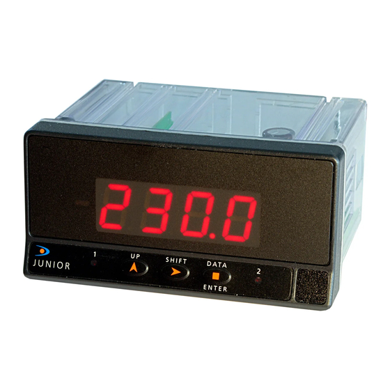
- Page 1 JR-C / JR20-C USER MANUAL JUNIOR JR-C / JR20-C DIGITAL INDICATOR FOR LOAD CELL INPUT KOSMOS SERIE www.ditel.es...
-
Page 2: Table Of Contents
CONFIGURATION LOCK-OUT Lock-out menu ......................17 OUTPUT OPTION Description ........................19 Function modes description ................... 19 HI/LO mode activation ....................19 Time delay ........................ 19 Asymmetrical hysteresis ..................... 19 Installation ........................20 SPECIFICATIONS Technical specifications ....................21 KOSMOS SERIE www.ditel.es... -
Page 3: General Information
WARNING: Potential risk of danger. Read completely related instructions when this symbol appears in order to know the potential risk and to know how to avoid it. WARNING: Risk of electric shock. Instrument protected by double isolation or reinforced isolation. KOSMOS SERIE www.ditel.es... -
Page 4: Maintenance
All DITEL products benefit from an unlimited and inconditional warranty of three (3) years from the date of their purchase. Now you can extend this period up to five (5) years from the product commissioning, only by fulfilling the corresponding form. -
Page 5: Conformity Declaration
JR-C / JR20-C Conformity declaration Manufacturer: DITEL - Diseños y Tecnología S.A. EN 61326-1 Electrical equipment for measurement, control and Adress: Xarol, 8C P.I. Les Guixeres laboratory use (EMC) 08915 Badalona. SPAIN EN 61000-4-2 Electrostatic discharge (ESD) Criterion B Air discharge 8kV... -
Page 6: Device Description
To remove the instrument from the panel, pull outwards the rear fixing clips latching tabs until they are disengaged, then slide fixing clips back over the case. KOSMOS SERIE www.ditel.es... -
Page 7: Display And Keyboard
Cables section should be 0.25 mm². Before connecting signal wires, signal type and input range should be verified to be within the right limits. Do not connect simultaneously more than one input signal to the meter. KOSMOS SERIE www.ditel.es... -
Page 8: Connections
LOAD CELL CONNECTION WITH EXCITATION SUPPLIED BY THE INDICATOR INDICATOR LOAD CELL ±30mV ±300mV NOTE: +OUT -OUT The instrument can supply excitation to multiple load cells connected in parallel as long as 30mA of total load current is not exceeded. -IN (COMMON) +EXC. -EXC. KOSMOS SERIE www.ditel.es... -
Page 9: Remote Tare Function
Relays output wiring RELAY 2 RELAY 1 WARNING: Read recommendations and related data on pages 7 and 8. IMPORTANT: To guarantee electrical safety according to EN 61010-1 a protective 8A/250V external fuse must be installed. 8A/250V MAX. KOSMOS SERIE www.ditel.es... -
Page 10: Input Configuration
The first menu corresponds to input configuration. This, in turn, consists of two options, one for each input type: (300) and (30). No additional configuration is needed for these input types (direct validation). SIGNAL TYPE: 300: Input signal up to ±300mV DC Input signal up to ±30mV DC KOSMOS SERIE www.ditel.es... -
Page 11: Input Configuration
EXCITATION LEVEL: Configurable value: E 5: 5V DC E 10: 10V DC Once input range is selected, the routine goes to configure excitation. 5V and 10V are available. In both cases load current limit is 30mA DC. KOSMOS SERIE www.ditel.es... -
Page 12: Display Configuration
2mV/V load cell with a 10V DC DISPLAY 1 DISPLAY 2 excitation. Decimal point is DISP.1 (00.0) situated between third and fourth digit of the display. INPUT 1 INPUT 2 INPUT 1 INPUT 2 INP.1 INP.2 (0.00) (20.00) KOSMOS SERIE www.ditel.es... -
Page 13: Mv Input
TARE value. Value Fc (Hz) Value Fc (Hz) FiLt 0.35 WEIGHTED AVERAGE FILTER: 1.20 0.29 0.44 0.23 FiLt: 0 to 8 Configurable 0.41 0.18 0.38 KOSMOS SERIE www.ditel.es... -
Page 14: Setpoints Configuration
If 2RE output option card is uninstalled, the instrument keeps setpoints last configuration in memory, though it can not be visualized. Thanks to this feature there will be no need to reconfigure relays setting when 2RE output option is again installed if the same configuration is required. KOSMOS SERIE www.ditel.es... -
Page 15: Available Keyboard Functions
FIRST SETPOINT VALUE: 00.00 SEt1: Setpoint 1 value indication. 00.00: Value entering in counts within available model display range. SEt2 SECOND SETPOINT VALUE: 00.00 SEt2: Setpoint 2 value indication. 00.00: Value entering in counts within available model display range. KOSMOS SERIE www.ditel.es... -
Page 16: Return To Default Configuration
Display shows now “CodE” and then “0000”. Desired security code must be introduced CodE through SHIFT and UP keys (by default this code is 0000). Finally press ENTER to begin with lock-out level configuration. If entered security code 0000 is wrong, the instrument will go back to RUN mode. KOSMOS SERIE www.ditel.es... -
Page 17: Configuration Lock-Out
If 2RE output option card is uninstalled, the instrument keeps setpoints last configuration in memory, though it can not be visualized. There will be no need to reconfigure setpoints lock-out when 2RE output option is again installed if the same configuration is required. KOSMOS SERIE www.ditel.es... - Page 18 Once the instrument programming is completed, if there are parameters that are going to be frequently changed, a partial lock-out is recommended. A total lock-out is recommended when configuration parameters will be constant for a long time. Changing default security code and keep new one in a safe place is also strongly recommended. KOSMOS SERIE www.ditel.es...
-
Page 19: Output Option
‘hys-1’ delay as indicated on the right figure. Note that outputs activation is not affected by hysteresis and they activate in each case just when Hysteresis delay for OUT1 (HI mode) and for OUT2 (LO mode) setpoint ‘SET’ is reached by display. KOSMOS SERIE www.ditel.es... -
Page 20: Installation
Disconnect all power and rest of input signals connected to the indicator before installing or extracting the output option card. Once 2RE is installed and instrument is again inside the case, 2RE connectors should come out through the obtained orifice as this figure shows. KOSMOS SERIE www.ditel.es... -
Page 21: Specifications
EMI max. Influence (±300mV) ........±60V Maximum input signal (±30mV) ........±32mV Maximum input signal (±300mV) ........ ±320mV RANGE RESOLUTION ACCURACY ±30mV 1V ±(0.05%rdg + 6V) ±300mV 15V ±(0.05%rdg + 60V) FILTER Cutoff frequency (-3dB) ........ 1.20Hz to 0.18Hz Slope ..............-20dB/Dec. KOSMOS SERIE www.ditel.es... - Page 22 Use the following template for the annotation of configured parameters in your instrument for later consulting or data recover. INPUT: TYPE: RANGE: DISPLAY: SCAL TEACH CONFIG. MODE: INPUT 1: DISPLAY 1: INPUT 2: DISPLAY 2: FILTER (0 ÷ 8): SETPOINTS: SET1: MODE: DLY: HYS: SET2: MODE: DLY: HYS: LOCK-OUT: ACCESS CODE: KOSMOS SERIE www.ditel.es...
- Page 23 JR-C / JR20-C DISEÑOS Y TECNOLOGÍA, S.A. Tel. +34 933 394 758 Xarol, 8-C P.I. Les Guixeres Fax +34 934 903 145 KOSMOS SERIE www.ditel.es 08915 Badalona - Spain. Email: dtl@ditel.es ; web: www.ditel.es 30727437 02.04.2013...
Need help?
Do you have a question about the JUNIOR JR-C and is the answer not in the manual?
Questions and answers