Table of Contents
Advertisement
SICAM TM
Installation
DC6-015-2.04
___________________________________________________________________________
Preface, Table of Contents
___________________________________________________________________________
Architecture
___________________________________________________________________________
Components
___________________________________________________________________________
Assembly
___________________________________________________________________________
Wiring Communication
___________________________________________________________________________
Wiring for the Reception of Time Signals
___________________________________________________________________________
Wiring Watchdog and Error
___________________________________________________________________________
Power
Supply
___________________________________________________________________________
Wiring Peripheral Elements
___________________________________________________________________________
Wiring Process
Peripherals
___________________________________________________________________________
Shielding / Protective Earthing
___________________________________________________________________________
Labelling
___________________________________________________________________________
Parameter Setting Preparation
___________________________________________________________________________
Recommended and tested purchased
products
___________________________________________________________________________
Licensing Agreement
___________________________________________________________________________
Literature
___________________________________________________________________________
1
2
3
4
5
6
7
8
9
10
11
12
A
B
Advertisement
Table of Contents

Related Manuals for Siemens SICAM TM


Summary of Contents for Siemens SICAM TM
- Page 1 ___________________________________________________________________________ Preface, Table of Contents ___________________________________________________________________________ Architecture ___________________________________________________________________________ SICAM TM Components ___________________________________________________________________________ Installation Assembly ___________________________________________________________________________ Wiring Communication ___________________________________________________________________________ Wiring for the Reception of Time Signals ___________________________________________________________________________ Wiring Watchdog and Error ___________________________________________________________________________ Power Supply ___________________________________________________________________________ Wiring Peripheral Elements ___________________________________________________________________________ Wiring Process...
- Page 2 Disclaimer of Liability Copyright Although we have carefully checked the contents of this publication Copyright © Siemens AG 2014 for conformity with the hardware and software described, we cannot The reproduction, transmission or use of this document or its guarantee complete conformity since errors cannot be excluded.
- Page 3 SICAM TM Purpose of this manual This handbook describes how the hardware of a SICAM TM system is to be installed and which preparations are to be made for the subsequent parameter settings. Thereby the following points are described step-by-step: ·...
- Page 4 The equipment (device, module) must not be used for any other purposes than those described in the Catalog and the Technical Description. If it is used together with third-party devices and components, these must be recommended or approved by Siemens. Correct and safe operation of the product requires adequate transportation, storage, installation, and mounting as well as appropriate use and maintenance.
-
Page 5: Table Of Contents
16 Peripheral Elements SICAM TM, electrically connected ....... 12 1.2.3. 16 Peripheral Elements SICAM TM, optically connected ......13 1.2.4. 16 Peripheral Elements SICAM TM, electrically and optically connected ... 14 Components ........................ 15 2.1. Master Control Modules .................. 16 2.2. - Page 6 Master Control Element CP-6014 ó Peripheral Control Module PE-6410 ..77 8.2. Master Control Element CP-6014 ó Bus Interface Module CM-084x ..... 78 8.3. Bus Interface Module CM-0843 ó Peripheral Control Module PE-6410 ..79 8.4. SICAM TM, Installation Edition 10.2014, DC6-015-2.04...
- Page 7 Terminal Coding ................... 102 Parameter Setting Preparation ................. 103 12.1. Introduction ....................104 12.2. Physical connection between SICAM TOOLBOX II and SICAM TM ....104 12.2.1. Direct connection via toolbox cable ............... 105 12.2.2. Serial via modem ..................106 12.2.3.
- Page 8 Table of Contents A.5. Power Supplies .................... 117 Licensing Agreement ....................119 B.1. Open Source Software used in SICAM TM ........... 119 B.1.1. Readout of ReadmOSS.htm ..............119 SICAM TM, Installation Edition 10.2014, DC6-015-2.04...
-
Page 9: Architecture
Architecture Content 1.1. Mechanical Design ..................10 1.2. Configurations (Examples)................11 SICAM TM, Installation DC6-015-2.04, Edition 10.2014... -
Page 10: Mechanical Design
1.1. Mechanical Design A SICAM TM system consists of one master control element, up to a maximum of 4 bus interface modules (electrical and/or optical) and up to 16 peripheral elements. A peripheral element consists of a power supply module, a peripheral control module and up to a maximum of 8 I/O-modules. -
Page 11: Configurations (Examples)
Architecture 1.2. Configurations (Examples) 1.2.1. 2 Peripheral Elements SICAM TM, electrically connected CP-6014 Communication with other automation units Ax 1703 peripheral bus (electrical) 16 Mbps USB cable, length up to 3 m .. -
Page 12: Peripheral Elements Sicam Tm, Electrically Connected
Architecture 1.2.2. 16 Peripheral Elements SICAM TM, electrically connected CP-6014 Note: all in all up to 16 peripheral elements Ax 1703 peripheral bus (electrical) 16 Mbps patch cable, length up to 3 m Communication with other 1 . . . 4... -
Page 13: Peripheral Elements Sicam Tm, Optically Connected
Architecture 1.2.3. 16 Peripheral Elements SICAM TM, optically connected CP-6014 Note: all in all up to 16 peripheral elements Ax 1703 peripheral bus (electrical) 16 Mbps patch cable, length up to 3 m Communication with other 1 . . . 4... -
Page 14: Peripheral Elements Sicam Tm, Electrically And Optically Connected
Architecture 1.2.4. 16 Peripheral Elements SICAM TM, electrically and optically connected CP-6014 Note: all in all up to 16 peripheral elements Ax 1703 peripheral bus (electrical) 16 Mbps communication with other patch cable, length up to 3 m automation units 1 . -
Page 15: Components
Components Content 2.1. Master Control Modules .................. 16 2.2. Serial Interface Modules ................. 17 2.3. Bus Interface Module ..................19 2.4. Power Supplies ....................19 2.5. Peripheral Modules..................20 SICAM TM, Installation DC6-015-2.04, Edition 10.2014... -
Page 16: Master Control Modules
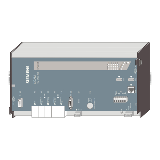
Components 2.1. Master Control Modules Designation Item Number/ MLFB CP6014 Master Control Module GC6-014 6MF11130GA140AA0 SICAM TM, Installation Edition 10.2014, DC6-015-2.04... -
Page 17: Serial Interface Modules
Serial Interface Processor 2 SI 6MF10130CF510AA0 SM-0551 BC0-551 Serial Interface Processor 1 SI 6MF10130AF510AA0 2.2.2. Network Interface Processor (NIP) Designation Item Number/ MLFB SM-2557 BC2-557 Network-Interf.Ethernet 2x100TX 6MF10130CF570AA0 SM-2558 Ethernet-Interf. 1x100TX BC2-558 + 1 serial interface optional 6MF10130CF580AA0 SICAM TM, Installation DC6-015-2.04, Edition 10.2014... -
Page 18: Field Bus Interface Processor (Fip)
Components 2.2.3. Field Bus Interface Processor (FIP) Designation Item Number/ MLFB SM-2545 BA2-545 Profibus Interface (Master) 6MF10110CF450AA0 SICAM TM, Installation Edition 10.2014, DC6-015-2.04... -
Page 19: Bus Interface Module
6MF11110AJ430AA0 CM-0842 GA0-842 Ax 1703-Businterface 4x fiber optical 6MF11110AJ420AA0 2.4. Power Supplies Designation Item Number/ MLFB PS-6630 Power Supply Module GC6-630 24-60 VDC (EMC+) 6MF11130GG300AA0 PS-6632 Power Supply Module GC6-632 110-220 VDC (EMC+) 6MF11130GG320AA0 SICAM TM, Installation DC6-015-2.04, Edition 10.2014... -
Page 20: Peripheral Modules
Ax-PE-Bus (electrical) 6MF11130GE000AA0 PE-6411 Peripheral Controller GC6-411 (1x Ax-PE bus opt) 6MF11130GE110AA0 PE-6412 Peripheriekopplung GC6-412 (2x Ax-PE Bus opt) 6MF11130GE120AA0 DI-6100 Binary Input 2x8, GC6-100 24-60VDC 6MF11130GB000AA0 DI-6101 Binary Input 2x8, GC6-101 110/220VDC 6MF11130GB010AA0 SICAM TM, Installation Edition 10.2014, DC6-015-2.04... - Page 21 24-60VDC 1ms 6MF11130GB020AA0 DI-6103 Binary Input 2x8, GC6-103 110/220VDC 1ms 6MF11130GB030AA0 DI-6104 Binary Input 2x8, 220VDC GC6-104 6MF11130GB040AA0 DO-6200 Binary Output Transistor GC6-200 2x8, 24-60VDC 6MF11130GC000AA0 DO-6212 Binary Output Relays 8x GC6-212 24-220VDC/230VAC 6MF11130GC200AA0 SICAM TM, Installation DC6-015-2.04, Edition 10.2014...
- Page 22 DO-6220 Command Out Basic GC6-220 Module 6MF11130GC200AA0 DO-6221 Command Out Basic GC6-221 Module Measure 6MF11130GC210AA0 DO-6230 Command Out Relay GC6-230 Module 6MF11130GC300AA0 AI-6300 Analog Input 2x2 GC6-300 ±20mA/±10V 6MF11130GD000AA0 AI-6307 Analog Input 2x2 ±5mA GC6-307 6MF11130GD070AA0 SICAM TM, Installation Edition 10.2014, DC6-015-2.04...
- Page 23 Components AI-6310 Analog Input 2x2 GC6-310 Pt100/Ni100 6MF11130GD100AA0 AO-6380 Analog Output 4x GC6-380 ±20mA/±10mA/±10V 6MF11130GD800AA0 TE-6420 Speed Measurement 2x2 GC6-420 5VDC/24VDC/NAMUR 6MF11130GE200AA0 TE-6450 Position Acquisition 2x2 GC6-450 SSI/RS-422 6MF11130GE500AA0 SICAM TM, Installation DC6-015-2.04, Edition 10.2014...
-
Page 25: Assembly
Installation of TS35 Rail (DIN Rail) ..............30 3.4. Installation of Cable Duct ................31 3.5. Installation of Master Control Element............. 32 3.6. Installation of Bus Interface Modules .............. 35 3.7. Installing TM Modules ..................37 SICAM TM, Installation DC6-015-2.04, Edition 10.2014... -
Page 26: Necessary Material
3.1. Necessary Material Due to the different circumstances with the local installation of the SICAM TM systems, not all details such as e.g. screw sizes, cable lengths and the like can be dealt with in this document. Therefore only recommendations and minimum requirements are specified concerning consumables. -
Page 27: How And Where Can Installation Take Place
3.2.2. Installation Position SICAM TM systems may only be installed horizontally or vertically. The vertical installation is to be preferred, since this provides a considerably more space-saving and efficient installation. The cabling of external cables is also made significantly easier as a result. -
Page 28: Space Requirement
3.2.3. Space Requirement The space requirement of a completely configured SICAM TM peripheral element (power supply, master control unit, up to 8 I/O modules) in the width comes to 630 mm (without end bracket and terminal strip marker for the system designation). -
Page 29: Environmental Conditions
The permissible temperature range for the operation of the modules is about –25°..+70°C (except CM-0842, only up to +55°C). For details on the subject of environmental conditions, please refer to the SICAM TM System Data Sheet (MC6-007-1), chapter: "Climatic Ambient Conditions and Electrical Ambient Conditions". -
Page 30: Installation Of Ts35 Rail (Din Rail)
The orientation and position in which the TS35 rail is to be installed must be determined locally. Take into account the details specified in chapter 3.2.3, "Space Requirement" Caution By means of the connection TS35 rail - cabinet/rack a reliable grounding connection must be guaranteed. SICAM TM, Installation Edition 10.2014, DC6-015-2.04... -
Page 31: Installation Of Cable Duct
20 mm for cabling without lead labeling. If the leads are to be fitted with labeling bushes, the minimum distance is 30 mm (refer to chapter 3.2.3, "Space Requirement" ). SICAM TM, Installation DC6-015-2.04, Edition 10.2014... -
Page 32: Installation Of Master Control Element
. One then turns the housing until the white spring retainer has contact with ‚. ƒ the lower edge of the rail By pressing on the housing the spring retainer opens a little „ and the housing snaps into the guide. SICAM TM, Installation Edition 10.2014, DC6-015-2.04... -
Page 33: Removal/Shifting Of The Master Control Element
After shifting the master control element the spring retainers must be closed again in order to „ fix the housing. For this a slight push on the spring retainer is sufficient to bring it back to the closed position. SICAM TM, Installation DC6-015-2.04, Edition 10.2014... -
Page 34: Securing Master Control Element Against Slipping
Assembly 3.5.2. Securing Master Control Element against Slipping If the master control element is installed vertically, it must be secured against slipping with an end bracket. SICAM TM, Installation Edition 10.2014, DC6-015-2.04... -
Page 35: Installation Of Bus Interface Modules
. One then turns the housing until the carrier rail retainer also ‚. ƒ has contact with the lower edge of the rail By pressing on the housing the retainer „ opens a little and the housing snaps into the guide. SICAM TM, Installation DC6-015-2.04, Edition 10.2014... -
Page 36: 3.6.1.1. Removing/Shifting The Optical Bus Interface Module
The electrical Ax Bus Module can be installed on the TS35 rail and removed again by hand, without any tools. For details concerning the handling of a TM module refer to section 3.7, Installing TM Modules. SICAM TM, Installation Edition 10.2014, DC6-015-2.04... -
Page 37: Installing Tm Modules
With the screw terminal, as an option there exists the possibility of a mechanical terminal coding (refer to chapter 11.6; "Terminal Coding"). Connection Diagrams These are located on the underside of the modules. They indicate examples of the external circuitry of the modules. SICAM TM, Installation DC6-015-2.04, Edition 10.2014... -
Page 38: Handling
The number and meaning of the displays on the front panel are, apart from the RY-LED, different on all modules. While the RY-LED always displays the functional readiness of the module, the meaning of the other displays is to be taken from the respective description (SICAM TM I/O Modules). 3.7.2. Handling The modules can be installed on the TS35 rail and removed again by hand, without any tools. -
Page 39: Connection
It is correct, when with vertical installation position of the system, the lettering on the front panel can be read from left to right. With horizontal installation position of the system, it must be possible to read the lettering on the front panel from botton to top. SICAM TM, Installation DC6-015-2.04, Edition 10.2014... -
Page 40: Order
In addition, with vertical installation an end bracket is also to be fitted. This prevents the modules from shifting due to their own weight. Designation Item Number Endhalter Clipfix 35 PHO+3022218 SICAM TM, Installation Edition 10.2014, DC6-015-2.04... -
Page 41: Wiring Communication
Wiring Communication Content 4.1. Introduction ....................42 4.2. Configuring Master Control Element with Serial Interface Modules (SIM) ..43 4.3. Wiring Communication..................50 SICAM TM, Installation DC6-015-2.04, Edition 10.2014... -
Page 42: Introduction
Wiring Communication 4.1. Introduction Depending on the protocol elements incorporated in the master control element, SICAM TM provides different methods of communication (Serial V.28, V.11; Ethernet TCP/IP; Field Bus) to external data transmission systems. · Serial communication ─ Point-to-point traffic according to IEC 60870-5-101 ─... -
Page 43: Configuring Master Control Element With Serial Interface Modules (Sim)
In order to perform this task the housing of the master control element must be opened. ATTENTION OBSERVE PRECAUTIONS FOR HANDLING ELECTROSTATIC SENSITIVE DEVICES SICAM TM, Installation DC6-015-2.04, Edition 10.2014... -
Page 44: Opening The Housing
„ … mounting with a push to the rear . Now the back panel of the housing can be removed and one can begin with the installation of the SIMs. SICAM TM, Installation Edition 10.2014, DC6-015-2.04... -
Page 45: Removing/Fitting The Sim Retainer
To remove these clips one presses that end of the clip, which is snapped on to the underside ‚ of the housing, inwards and then by pulling the clip one withdraws it from the housing. SICAM TM, Installation DC6-015-2.04, Edition 10.2014... -
Page 46: Installing Patch Plugs And Sims
This protection is available in CP-6010 and CP-6014. A patch plug is then correctly fitted when PIN 1 of the patch plug is slotted in the hole of the respective slot marked with 1. SICAM TM, Installation Edition 10.2014, DC6-015-2.04... -
Page 47: Fixing The Sims
To fit these fastening clips, one first guides the wide end of the clip in the recess on the inside ‚ of the housing and then presses the thin end , possibly with the help of a narrow screw- driver, into the anchoring between SIM card and housing. SICAM TM, Installation DC6-015-2.04, Edition 10.2014... - Page 48 The clip is only then correctly fixed, when it snaps on to the housing and presses on the SIM card. Mounting SM-0551 SIM SM-0551 is not mounted directly on the main board like the other SIM, it must be mounted on a SM-2558 before. SM-2558 SM-0551 SICAM TM, Installation Edition 10.2014, DC6-015-2.04...
-
Page 49: Configuration Notes
SM-2545 (FIP) SIM1 – – – – – – SM-0551 (SIP) SIM0 – – – – SM-0551 must be mounted on SM-2558 Due to thermal rasons only one SM-2545 (on SIM1) may be equipped SICAM TM, Installation DC6-015-2.04, Edition 10.2014... -
Page 50: Wiring Communication
Wiring Communication 4.3. Wiring Communication Hint Communication cables are, if possible, to be installed separately from the supply and peripheral cables. SICAM TM, Installation Edition 10.2014, DC6-015-2.04... -
Page 51: Serial Communication
Patch cable 0.3m Accessories Designation Item Number/ MLFB CE-0700 – V.23 dedicated line G21-200 modem 6MF11020BC000AA0 CE-0701 - WT channel modem f. G22-081 DIN-rail 6MF11020CA810AA0 TPP_0.3M TP Patch Cable 0.3m T41-257 Cat 5 6MF13040BC570AA0 SICAM TM, Installation DC6-015-2.04, Edition 10.2014... -
Page 52: 4.3.1.2. Multi-Point Traffic Via Glass Fibre Optic And Star Connection
Accessoires Designation Item Number/ MLFB CM-0827 - Fiberoptik-Interface (el.- GA0-827 LWL) 6MF11110AJ270AA0 Fibre optics FO-INDOORCABLE-50-DUP-LSOH TF7-027 length: max. 0,5km FO-OUTDOORCABLE-50-2FIB-ARM TF7-028 FO-CONNECTOR-ST-50/62 TF7-016 Fibre optics FO-INDOORCABLE-62-DUP-LSOH TF7-006 length: max. 1,5km FO-OUTDOORCABLE-62-2FIB-ARM TF7-007 FO-CONNECTOR-ST-50/62 TF7-016 SICAM TM, Installation Edition 10.2014, DC6-015-2.04... -
Page 53: 4.3.1.3. Analog Dial-Up Traffic
Master control element CP-6014 Eurocom 24 Modem SM-2551 SM-0551 on SM-2558 CM-2860 max. 300 mm SI0-3 Accessories see Appendix A, Recommended and tested purchased products Cable Circuitry Master Control Element – Eurocom 24 Modem CP-6014 SICAM TM, Installation DC6-015-2.04, Edition 10.2014... -
Page 54: 4.3.1.3.1. Westermo Td36 Modem With External Power Supply
20 - 264VAC / 14 - 300VDC (TD-36 AV) 10 - 30VAC / 10 - 60VDC (TD-36 LV) Accessories see Appendix A, Recommended and tested purchased products Cable Circuitry Master Control Element – Westermo TD-36 SICAM TM, Installation Edition 10.2014, DC6-015-2.04... -
Page 55: 4.3.1.4. Dial-Up Traffic Analog/Gsm/Isdn
SM-0551 on SM-2558 CM-2860 max. 25 m Power SI0-3 supply 12 - 48VAC / 12 - 34VAC (IDW-90 LV) Accessories see Appendix A, Recommended and tested purchased products Cable Circuitry Master Control Unit – Westermo IDW-90 SICAM TM, Installation DC6-015-2.04, Edition 10.2014... -
Page 56: 4.3.1.5. Gsm Dial-Up Traffic
Wiring Communication 4.3.1.5. GSM Dial-up Traffic SM-2551 Master control element CP-6014 8 - 30VDC (Siemens TC35) SM-0551 on SM-2558 Power supply CM-2860 GSM Modem SI0-3 Accessories see Appendix A, Recommended and tested purchased products Cable Circuitry Master Control Unit – GSM Modem Variant for the deactivation function of the TC35 GSM modem controlled by SICAM RTUs. - Page 57 Wiring Communication Variant without the deactivation function of the TC35 GSM modem controlled by SICAM RTUs. SICAM TM, Installation DC6-015-2.04, Edition 10.2014...
-
Page 58: Lan Communication (Ethernet Tcp/Ip)
Details for connections over 10m can TF5-200 (1.5m) be taken from document: 6MF13140FC000AA0 Configuration Automation Units and TF5-201 (3m) Automation Networks (DC2-021); 6MF13140FC010AA0 Appendix A; Chapter: Electrical TF5-202 (5m) Connection, Cable longer than 10m. 6MF13140FC020AA0 SICAM TM, Installation Edition 10.2014, DC6-015-2.04... -
Page 59: Field Bus/Profi Bus Communication
CM-2869 Patch Plug SMI-RS485 CA2-869 6MF12112CJ600AA0 The latest version of this patch plug, item number CA2-869-B, is already modified according to following illustration (thick line). This modification must be added on older versions of the patch plug. SICAM TM, Installation DC6-015-2.04, Edition 10.2014... - Page 60 Wiring Communication SICAM TM, Installation Edition 10.2014, DC6-015-2.04...
-
Page 61: Wiring For The Reception Of Time Signals
Wiring for the Reception of Time Signals Content 5.1. DCF77 Receiver ..................... 62 5.2. GPS Satellite Receiver ................... 63 5.3. LAN Time Server .................... 65 SICAM TM, Installation DC6-015-2.04, Edition 10.2014... -
Page 62: Dcf77 Receiver
DCF77- Receiver Master control element CP-6014 N connector RG58 Lightning X11 SYNC protection BNC-Connector RG58 Designation Item Number/ MLFB DCF77- Receiver for DIN rail GA0-806 6MF11110AJ060AA0 Accessories see Appendix A, Recommended and tested purchased products SICAM TM, Installation Edition 10.2014, DC6-015-2.04... -
Page 63: Gps Satellite Receiver
The minute pulse is supplied on the screw terminal on the front panel of the GPS164 receiver. GPS167 Antenna/converter RG58 Lightning Protection Antenna connecting kit GPS164 Master control element CP-6014 Receiver Power Supply 24 VDC X11 SYNC Accessories see Appendix A, Recommended and tested purchased products SICAM TM, Installation DC6-015-2.04, Edition 10.2014... -
Page 64: Wiring For The Receipt Of The Serial Time Signal
Master control element CP-6014 Receiver Power Supply 24 VDC COM 0 X11 SYNC Accessories see Appendix A, Recommended and tested purchased products Wiring cable GPS164 – CP-6014 9 pol. GPS164 DSUB (COM 0) CP-6014 male X11/+ X11/- SICAM TM, Installation Edition 10.2014, DC6-015-2.04... -
Page 65: Lan Time Server
NTP Server in 19" case for TCP/IP networks with integrated HTTP-Server. The internal reference time is derived from a built-in GPS receiver of the type GPS167. Master control element CP-6014 SM-2557, SM-2558 Network Interface SI1 (ETO) Ethernet TCP/IP 60870-5-104 LAN time server SICAM TM, Installation DC6-015-2.04, Edition 10.2014... - Page 66 Wiring for the Reception of Time Signals SICAM TM, Installation Edition 10.2014, DC6-015-2.04...
-
Page 67: Wiring Watchdog And Error
Wiring Watchdog and Error Content 6.1. Introduction ....................68 SICAM TM, Installation DC6-015-2.04, Edition 10.2014... -
Page 68: Introduction
Introduction The relay contacts (normally open contact and normaly closed contact) of watchdog and error are available on plug X5 of the master control element. Master control element CP-6014 Watchdog (WD) Error (ER) CP-6014 SICAM TM, Installation Edition 10.2014, DC6-015-2.04... -
Page 69: Power Supply
7.3. Power Supply Peripheral Element (Power Supply Module PS-663x) ....71 7.4. Power Supply Bus Interface Module (CM-0842) ..........72 7.5. Fuse Protection ....................73 7.6. Primary Mains Unit / Standard Type ............... 73 SICAM TM, Installation DC6-015-2.04, Edition 10.2014... -
Page 70: Introduction
Power Supply 7.1. Introduction The following components must be supplied with 24-60VDC in a SICAM TM System: · Master Control Element · Peripheral Elements · Optical Bus Interface Modules The supply can be carried out with single leads of the type H07V-K (1.5-2.5) or a cable of the type LA-YY-0 (2x1.5-2.5) or H05VV-F3G (1.5-2.5) respectively. -
Page 71: Power Supply Peripheral Element (Power Supply Module Ps-663X)
· The systen has to provide a circuit breaker for disconnection. · The power supply modules require no maintenance. In case of damage, the device may not be opened. SICAM TM, Installation DC6-015-2.04, Edition 10.2014... -
Page 72: Power Supply Bus Interface Module (Cm-0842)
If several optical bus interface modules are used in one system, each must be supplied separately with power. This is also applicable if the modules are connected with each other by means of the interface connector. SICAM TM, Installation Edition 10.2014, DC6-015-2.04... -
Page 73: Fuse Protection
One miniature circuit breaker is recommended for each peripheral element. 7.6. Primary Mains Unit / Standard Type See Appendix A, Recommended and tested purchased products SICAM TM, Installation DC6-015-2.04, Edition 10.2014... -
Page 75: Wiring Peripheral Elements
Bus Interface Module CM-0843 ó Peripheral Control Module PE-6410 ..79 8.4. Bus Interface Module CM-0842 ó Peripheral Control Module PE-6411, PE- 8.5. 6412 ....................... 80 Bus Interface Module CM-0842 ó Bus Interface Module CM-0843 ....81 8.6. SICAM TM, Installation DC6-015-2.04, Edition 10.2014... -
Page 76: Introduction
8.1. Introduction The peripheral elements of a SICAM TM system communicate with the master control element via the serial Ax 1703 peripheral bus. The cabling of this Ax peripheral bus is dependent on the number of peripheral elements that are to be connected and whether the connection is to be carried out electrically or/and optically. -
Page 77: Master Control Element Cp-6014 Ó Peripheral Control Module Pe-6410
Ax 1703 peripheral bus (electrical) USB cable up to 3m Designation Item Number / MLFB USB-Cable for Peripheral Controller TC6-201 (1,5m) 6MF13130GC010AA0 USB-Cable for Peripheral Controller TC6-202 (2,0m) 6MF13130GC020AA0 USB-Cable for Peripheral Controller TC6-203 (3,0m) 6MF13130GC030AA0 SICAM TM, Installation DC6-015-2.04, Edition 10.2014... -
Page 78: Master Control Element Cp-6014 Ó Bus Interface Module Cm-084X
Ax 1703 peripheral bus (electrical) Patch cable up to 3m Bus interface module CM-0843 (electrical) Designation Item Number/ MLFB Ax-Bus Patch Cable DSUB to RJ45 T41-255 (1m) 3m Cat5 6MF13040BC550AA0 T41-251 (2m) 6MF13040BC510AA0 T41-252 (3m) 6MF13040BC520AA0 SICAM TM, Installation Edition 10.2014, DC6-015-2.04... -
Page 79: Bus Interface Module Cm-0843 Ó Peripheral Control Module Pe-6410
Ax 1703 peripheral bus (electrical) USB cable up to 3m Designation Item Number / MLFB USB-Cable for Peripheral Controller TC6-201 (1,5m) 6MF13130GC010AA0 USB-Cable for Peripheral Controller TC6-202 (2,0m) 6MF13130GC020AA0 USB-Cable for Peripheral Controller TC6-203 (3,0m) 6MF13130GC030AA0 SICAM TM, Installation DC6-015-2.04, Edition 10.2014... -
Page 80: Bus Interface Module Cm-0842 Ó Peripheral Control Module Pe-6411, Pe-6412
Ax 1703 peripheral bus (optical) Fiber optic cable up to 200m length Components for fiber optic cable (0 .. 200m) Designation Item Number/ MLFB FO-INDOORCABLE-200-DUP TF7-033 FO-INDOORCABLE-200-DUP- TF7-034 BREAK FO-INDOORCABLE-200-DUP- TF7-035 BREAK-ROUND FO-OUTDOORCABLE-200-2FIB- TF7-036 FO-CONNECTOR-ODLP-200 TF7-015 SICAM TM, Installation Edition 10.2014, DC6-015-2.04... -
Page 81: Bus Interface Module Cm-0842 Ó Bus Interface Module Cm-0843
Patch cable up to 3m length Bus interface module CM-0842 (optical) Bus interface module CM-0843 (electrical) Designation Item Number/ MLFB Patch cable CAT5 (4x2) AWG26/7 T41-255 (1m) 6MF13040BC550AA0 T41-251 (2m) 6MF13040BC510AA0 T41-252 (3m) 6MF13040BC520AA0 SICAM TM, Installation DC6-015-2.04, Edition 10.2014... - Page 82 Wiring Peripheral Elements SICAM TM, Installation Edition 10.2014, DC6-015-2.04...
-
Page 83: Wiring Process Peripherals
Wiring Process Peripherals Content 9.1. Wiring Process Peripherals ................84 9.2. Peripheral Connector ..................85 9.3. TE-6450 – Wiring the Data Transmission ............86 9.4. Wiring of analog measured values ..............88 SICAM TM, Installation DC6-015-2.04, Edition 10.2014... -
Page 84: Wiring Process Peripherals
"Space Requirement"). Warning The activities described in this chapter presume that the grounding connection between SICAM TM and cabinet or rack has been properly carried out and that these are earthed. Warning For modules that operate with voltages >60V (e.g.: DO-6212, DI-6101) care must be taken that manipulation on the peripheral connectors may only be carried out in a de-energized state. -
Page 85: Peripheral Connector
Item Number / MLFB Labeled screw terminal (1-10); without coding Labeled screw terminal (11-20); without coding Labeled screw terminal (21-30); without coding Labeled screw terminal (31-40); without coding Withdrawal aid for terminals TC6-200 6MF13130GC000AA0 SICAM TM, Installation DC6-015-2.04, Edition 10.2014... -
Page 86: Te-6450 - Wiring The Data Transmission
The screen clamp plates (4 pieces are supplied with the module) are fixed in the grounded terminal points 14, 18, 24 and 28. At the angle-/position sensor side, the cable screens must also be grounded. SICAM TM, Installation Edition 10.2014, DC6-015-2.04... - Page 87 Cable for the Supply For AUX V0+/- and AUX V1+/- one cable, at least 2 x 1mm , is used. Cable length between TE-6450 and Temposonics-Sensor Cable length (m) <20 <60 <180 Bit rate (kBit/s) SICAM TM, Installation DC6-015-2.04, Edition 10.2014...
-
Page 88: Wiring Of Analog Measured Values
Wiring Process Peripherals 9.4. Wiring of analog measured values During the wiring of measured values with single wires, the wires must be twisted. SICAM TM, Installation Edition 10.2014, DC6-015-2.04... -
Page 89: Shielding / Protective Earthing
Shielding / Protective Earthing Content 10.1. Shielding ......................90 10.2. Protective Earthing / Grounding ..............91 SICAM TM, Installation DC6-015-2.04, Edition 10.2014... -
Page 90: Shielding
There the screening is carried out with special clamps (screen clamp plate). (For details refer to section 9.3, "TE-6450 – Wiring the Data Transmission"). SICAM TM, Installation Edition 10.2014, DC6-015-2.04... -
Page 91: Protective Earthing / Grounding
10.2. Protective Earthing / Grounding When installing a SICAM TM system, attention is to be paid that the cabinet or rack used features a proper protective earthing / grounding. That means, that all electrical conducting parts must be connected large-surface and as short as possible with the cabinet spar. The cabinet spar itself must be connected with the existing grounding system. -
Page 93: Labelling
11.1. Introduction ....................94 11.2. Labeling Master Control Element ..............95 11.3. Labeling Peripheral Element ................97 11.4. Terminal Labeling ..................100 11.5. Individual Terminal Point Labeling ..............101 11.6. Terminal Coding ................... 102 SICAM TM, Installation DC6-015-2.04, Edition 10.2014... -
Page 94: Introduction
Labelling 11.1. Introduction This chapter shows how a SICAM TM system is to be labeled according to Standard. The following labels are provided: · Region- and Component Number · Plant- and Location Designation · Equipment Identification (EI) · PBA Number ·... -
Page 95: Labeling Master Control Element
Labeling Master Control Element The master control element is to be labeled with operational equipment designation, region- and component number. 11.2.1. Equipment Identification, Region Number, Component Number Designation Item Number Zack Strip ZB8/27 10 pcs PHO+0807216 SICAM TM, Installation DC6-015-2.04, Edition 10.2014... -
Page 96: 11.2.2. Plant- And Location Designation
Labelling 11.2.2. Plant- and Location Designation The parts used are identical with those for the region- and component number. SICAM TM, Installation Edition 10.2014, DC6-015-2.04... -
Page 97: Labeling Peripheral Element
Labelling 11.3. Labeling Peripheral Element 11.3.1. Region Number, Component Number, PBA Number The parts used are identical with those for the region- and component number. SICAM TM, Installation DC6-015-2.04, Edition 10.2014... -
Page 98: Plant- And Location Designation
If required, the plant- and location designation can however also take place on a further end bracket with terminal strip marker. This is fitted before the region- and component number. The parts used are identical with those for the region- and component number. SICAM TM, Installation Edition 10.2014, DC6-015-2.04... -
Page 99: Equipment Identification (Ei)
-Axx1.0 Periphery -Axx1.1 Periphery -Axx1.2 Periphery -Axx1.3 Periphery -Axx1.4 Periphery -Axx1.5 Periphery -Axx1.6 Periphery -Axx1.7 Periphery xx = 01 – 16 (Nummer des Peripherieelements) Designation Item Number Zack strip ZB 8/27 10 pcs PHO+0807216 SICAM TM, Installation DC6-015-2.04, Edition 10.2014... -
Page 100: Terminal Labeling
Labelling 11.4. Terminal Labeling The individual terminals are already labeled ex works. The numbering takes place consecutively from 1 – 20 (power supply module) or from 1 - 40 (on all I/O modules). SICAM TM, Installation Edition 10.2014, DC6-015-2.04... -
Page 101: Individual Terminal Point Labeling
Thereby an adhesive plate is labeled individually, and then stuck to the slanted surface of the housing cover. Designation Item Number Label sheet BMKL 50x12 wh f. Laser PHO+5032387 print DIN A4 sheet with 63 white adhesive labels SICAM TM, Installation DC6-015-2.04, Edition 10.2014... -
Page 102: Terminal Coding
Designation Item Number/ MLFB PHOENIX CR-MSTB/ Coding PHO+1734401 Element 6 pces Coding section for terminal strip TC6-055 6MF13130GA550AA0 SICAM TM, Installation Edition 10.2014, DC6-015-2.04... -
Page 103: Parameter Setting Preparation
Parameter Setting Preparation Content 12.1. Introduction ....................104 12.2. Physical connection between SICAM TOOLBOX II and SICAM TM ....104 12.3. Logical Connection between SICAM TOOLBOX II and SICAM TM....109 12.4. Flash Card ....................110 SICAM TM, Installation DC6-015-2.04, Ausgabedatum 10.2014... -
Page 104: Introduction
12.1. Introduction The SICAM TM system is parameterized with a PC on which the SICAM TOOLBOX II software is installed. For this, the SICAM TOOLBOX II and automation unit must be connected with each other and a Flash Card configured in the master control element: 12.2. -
Page 105: Direct Connection Via Toolbox Cable
Parameter Setting Preparation 12.2.1. Direct connection via toolbox cable SICAM TOOLBOX II and SICAM TM are connected direct via the toolbox cable. SICAM TOOLBOX II SICAM TM CM-0820/ADAP CM-1820 TB Connection Cable TB Adapter Designation Item Number/ MLFB CM-1820 TB Cable Set... -
Page 106: Serial Via Modem
Parameter Setting Preparation 12.2.2. Serial via modem SICAM TOOLBOX II and SICAM TM are connected via 2 serial modems. SICAM TOOLBOX II SICAM TM serial serial CM-1820 TB Connection Cable line, PSTN, Modem Modem GSM, ... SICAM TM, Installation Ausgabedatum 10.2014, DC6-015-2.04... -
Page 107: Via Ethernet (Tcp/Ip)
Parameter Setting Preparation 12.2.3. Via Ethernet (TCP/IP) SICAM TOOLBOX II and SICAM TM are connected via Ethernet (TCP/IP). For this, the master control element must be fitted with additional SIM's. For details refer to section 4.2; Configuring Master Control Element with Serial Interface Modules (SIM). -
Page 108: Via Ethernet (Tcp/Ip) And Terminal Server (Serial)
Parameter Setting Preparation 12.2.4. Via Ethernet (TCP/IP) and Terminal Server (serial) SICAM TOOLBOX II and SICAM TM are connected via ethernet (TCP/IP) and terminal server (serial). SICAM TOOLBOX II SICAM TM CM-0820/ADAP Ethernet TB Adapter (TCP/IP) Terminal CM-1820 TB Anschlusskabel... -
Page 109: Logical Connection Between Sicam Toolbox Ii And Sicam Tm
(automation unit, which can be accessed via a local automation unit; a continuous remote communication according to IEC 60870-5-101 or -104 is required) local automation unit SICAM TOOLBOX II SICAM TM remote AU engineering local AU engineering physical connection SICAM TM remote automation unit SICAM TM, Installation DC6-015-2.04, Ausgabedatum 10.2014... -
Page 110: Flash Card
12.4. Flash Card SICAM TM uses a flash card for the storage of parameters, user program, firmware codes for basis system elements and supplementary system elements and data of the decentralized archive (DEAR). This is located in the housing of the master control element. -
Page 111: Inserting Flash Card
. Hold the locking panel in this position and guide the flash card ƒ until it engages. Then the locking panel can be released again and the flash card is secured. Locking Panel Guide for flash card SICAM TM, Installation DC6-015-2.04, Ausgabedatum 10.2014... -
Page 112: Withdrawing Flash Card
Hold the locking panel in this position and push the flash card slightly inwards ‚ . As a result it is disengaged and springs out of the guide a few millimeters. The flash card ƒ can now be removed and the locking panel released again. SICAM TM, Installation Ausgabedatum 10.2014, DC6-015-2.04... -
Page 113: Recommended And Tested Purchased Products
Recommended and tested purchased products Content A.1. Modem ......................114 A.2. DCF77 Accessories ..................115 A.3. GPS Satellite Receiver / Accessories............116 A.4. LAN Time Server ..................117 A.5. Power Supplies .................... 117 SICAM TM, Installation DC6-015-2.04, Ausgabedatum 10.2014... -
Page 114: Modem
Standard modem for ISDN dial-up traffic Designation Manufacturer Westermo IDW-90 www.westermo.com Standard modem for GSM dial-up traffic Designation Item-Number Siemens TC35 (dual band modem) G21-030-- 6MF11020BA300AA1 Including DIN-rail installation kit and connection cable (1.5m) Without antenna! GSM antenna for outside installation G21-031--... -
Page 115: Dcf77 Accessories
KR-DCF/STAA DCF77 Stand. www.meinberg.de Outdoor Antenna. G12-107 6MF11010CB070AA0 KR-DCF/V4 DCF77 Antenna www.meinberg.de Terminal Block G12-106 6MF11010CB060AA0 Antenna cable (Coaxial cable RG58 TF5-050 C/U 50 Ohm) 6MF13140FA500AA0 DCF/GPS-BS Lightning Protec. CN- BA0-802 UB/E-BB 6MF10110AJ020AA0 GPS-antenna-connecting-kit TA0-801 6MF13110AJ010AA0 SICAM TM, Installation DC6-015-2.04, Ausgabedatum 10.2014... -
Page 116: Gps Satellite Receiver / Accessories
Meinberg GPS164DHS www.meinberg.de Receiver for TS35 GPS167-ANT/CON GPS-Antenna- www.meinberg.de /Converter. GPS-AV4 Antenna Terminal Block www.meinberg.de Antenna cable (Coaxial cable RG58 TF5-050 C/U 50 Ohm) 6MF13140FA500AA0 DCF/GPS-BS Lightning Protec. CN- BA0-802 UB/E-BB 6MF10110AJ020AA0 GPS-antenna-connecting-kit TA0-801 6MF13110AJ010AA0 SICAM TM, Installation Ausgabedatum 10.2014, DC6-015-2.04... -
Page 117: Lan Time Server
Manufacturer Meinberg NTP Server + Antenna + www.meinberg.de Cable A.5. Power Supplies Designation Manufacturer Power Supply 5V/2A www.syko.de SYKO EWS 01 U.06.05.20 82 – 264VAC or 36 – 350VDC Power S. 115/230VAC,100-375VDC- www.mtm-power.com 24VDC-50W SICAM TM, Installation DC6-015-2.04, Ausgabedatum 10.2014... - Page 118 Recommended and tested purchased products SICAM TM, Installation Ausgabedatum 10.2014, DC6-015-2.04...
-
Page 119: Sicam Tm, Installation
Insofar as the applicable Open Source Software License Conditions provide for it you can order the source code of the Open Source Software from your Siemens sales contact - against payment of the shipping and handling charges - for a period of at least 3 years since purchase of the Product. - Page 120 When the download is finished you will get the file SICAMOSS.zip. Unzip this file and save the therein contained file (SICAMOSS.exe) in the root path of the SD- card from which you want to readout the license agreement. SICAM TM, Installation Edition 10.2014, DC6-015-2.04...
- Page 121 Within these subfolders are again folders for each used firmware revision. These folders contain the corresponding license data. Path for ReadmeOSS: SD-Card:\OSS\<Firmwarename>\<Firmwarenumber>\<Revision>\ReadmOSS.htm. E.g.: SD-Card:\OSS\ETA4\02.01\ReadmOSS.htm Example of a ReadmOSS.htm: SICAM TM, Installation DC6-015-2.04, Edition 10.2014...
- Page 122 Licensing Agreement SICAM TM, Installation Edition 10.2014, DC6-015-2.04...
- Page 123 Literature System Data Sheet SICAM TM MC6-007-2 System Data Sheet CP-6014/CPCX65 DC6-034-2 System Element Manual PE-641x/TCIO66 DC6-036-2 System Element Manual PE-641x/USIO66 DC6-032-2 SICAM TM Operation and Service DC6-017-2 SICAM TM, Installation DC6-015-2.04, Edition 10.2014...
- Page 124 Literature SICAM TM, Installation Edition 10.2014, DC6-015-2.04...
Need help?
Do you have a question about the SICAM TM and is the answer not in the manual?
Questions and answers