Mitsubishi Electric FR-D700 Installation Manuallines
Hide thumbs
Also See for FR-D700:
- Instruction manual (290 pages) ,
- Manual (34 pages) ,
- Safety stop function instruction manual (14 pages)
Table of Contents
Advertisement
INVERTER
FR-D700
INSTALLATION GUIDELINE
FR-D740-012 to 160-EC
FR-D720S-008 to 100-EC
Thank you for choosing this Mitsubishi Inverter.
Please read through this Installation Guideline and a CD-ROM enclosed to operate this inverter correctly.
Do not use this product until you have a full knowledge of the equipment, safety information and
instructions.
Please forward this Installation Guideline and the CD-ROM to the end user.
PRODUCT CHECKING AND PARTS IDENTIFICATION ..........1
1
OUTLINE DIMENSION DRAWINGS ........................................3
2
WIRING ..................................................................................4
3
PRECAUTIONS FOR USE OF THE INVERTER .....................10
4
5
PARAMETER LIST ...............................................................13
6
TROUBLESHOOTING...........................................................18
7
CONTENTS
700
Advertisement
Table of Contents

Related Manuals for Mitsubishi Electric FR-D700


Summary of Contents for Mitsubishi Electric FR-D700
-
Page 1: Table Of Contents
INVERTER FR-D700 INSTALLATION GUIDELINE FR-D740-012 to 160-EC FR-D720S-008 to 100-EC Thank you for choosing this Mitsubishi Inverter. Please read through this Installation Guideline and a CD-ROM enclosed to operate this inverter correctly. Do not use this product until you have a full knowledge of the equipment, safety information and instructions. - Page 2 This Installation Guideline provides handling information and precautions for use of the equipment. Please forward this Installation Guideline to the end user. 2. Fire Prevention This section is specifically about safety matters CAUTION Do not attempt to install, operate, maintain or inspect the Install the inverter on a nonflammable wall without holes inverter until you have read through the Installation (so that nobody can touch the inverter heatsink on the...
- Page 3 (2) Wiring (5) Emergency stop CAUTION CAUTION Do not install a power factor correction capacitor or surge Provide a safety backup such as an emergency brake suppressor/capacitor type filter on the inverter output which will prevent the machine and equipment from side.
-
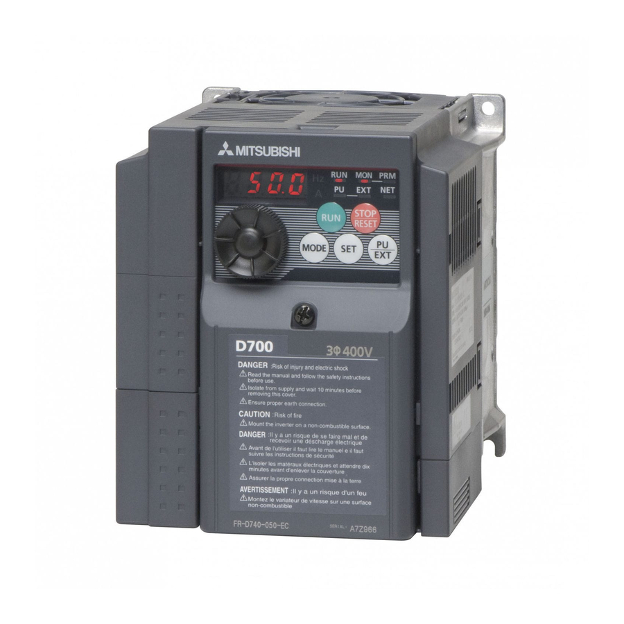
Page 4: Product Checking And Parts Identification
1 PRODUCT CHECKING AND PARTS IDENTIFICATION Unpack the inverter and check the capacity plate on the front cover and the rating plate on the inverter side face to ensure that the product agrees with your order and the inverter is intact. Inverter type Capacity plate - EC... - Page 5 PRODUCT CHECKING AND PARTS IDENTIFICATION General Precaution The bus capacitor discharge time is 10 minutes. Before starting wiring or inspection, switch power off, wait for more than 10 minutes, and check for residual voltage between terminal + and - with a meter etc., to avoid a hazard of electrical shock. Environment Before installation, check that the environment meets following specifications.
-
Page 6: Outline Dimension Drawings
2 OUTLINE DIMENSION DRAWINGS (Unit:mm) • Three-phase 400V class Inverter Type FR-D740-012 129.5 FR-D740-022 135.5 FR-D740-036 FR-D740-050 155.5 FR-D740-080 165.5 FR-D740-120 FR-D740-160 • Single-phase 200V class Inverter Type FR-D720S-008 80.5 FR-D720S-014 FR-D720S-025 142.5 FR-D720S-042 162.5 155.5 FR-D720S-070 FR-D720S-100... -
Page 7: Wiring
Terminal connection diagram 3 WIRING Terminal connection diagram Source logic 1. DC reactor (FR-HEL) Main circuit terminal When connecting a DC reactor, remove the Control circuit terminal jumper across P1- Single-phase power input *6 A brake transistor is not built-in to the Brake unit FR-D720S-008 and 014. -
Page 8: Main Circuit Terminal Specifications
WIRING Main circuit terminal specifications 3.2.1 Terminal arrangement of the main circuit terminal, power supply and the motor wiring Three-phase 400V class FR-D740-012 to 080 FR-D740-120, 160 Screw size (M4) Jumper Jumper R/L1 S/L2 T/L3 Screw size (M4) R/L1 S/L2 T/L3 Screw size (M4) Screw size... -
Page 9: Cables And Wiring Length
WIRING 3.2.2 Cables and wiring length (1) Cable sizes etc., of the main control circuit terminals and earth (ground) terminals Select the recommended cable size to ensure that a voltage drop will be 2% max. If the wiring distance is long between the inverter and motor, a main circuit cable voltage drop will cause the motor torque to decrease especially at the output of a low frequency. - Page 10 WIRING Total wiring length The overall wiring length for connection of a single motor or multiple motors should be within the value in the table below. 200V class Pr. 72 PWM frequency selection Setting (carrier frequency) or More 1 (1kHz) or less 200m 200m 300m...
-
Page 11: Control Circuit Specifications
WIRING Control circuit specifications (1) Control circuit terminal layout RUN SE S1 S2 SC Recommended cable size: 0.3mm to 0.75mm STF STR (2) Wiring method Wiring Use a bar terminal and a cable with a sheath stripped off for the control circuit wiring. For a single wire, strip off the sheath of the cable and apply directly. - Page 12 WIRING 3) Insert the wire into a socket. When using a stranded wire without a bar terminal, push a open/close button all the way down with a flathead screw driver, and insert the wire. Open/close button Flathead screwdriver Note When using a stranded wire without a bar terminal, twist enough to avoid short circuit with a nearby terminals or wires.
-
Page 13: Precautions For Use Of The Inverter
PRECAUTIONS FOR USE OF THE INVERTER 4 PRECAUTIONS FOR USE OF THE INVERTER The FR-D700 series is a highly reliable product, but incorrect peripheral circuit making or operation/handling method may shorten the product life or damage the product. Before starting operation, always recheck the following items. - Page 14 PRECAUTIONS FOR USE OF THE INVERTER (12) Do not apply a voltage higher than the permissible voltage to the inverter I/O signal circuits. Application of a voltage higher than the permissible voltage to the inverter I/O signal circuits or opposite polarity may damage the I/O devices.
-
Page 15: Failsafe Of The System Which Uses The Inverter
FAILSAFE OF THE SYSTEM WHICH USES THE INVERTER FAILSAFE OF THE SYSTEM WHICH USES THE INVERTER When a fault occurs, the inverter trips to output a fault signal. However, a fault output signal may not be output at an inverter fault occurrence when the detection circuit or output circuit fails, etc. -
Page 16: Parameter List
PARAMETER LIST 6 PARAMETER LIST For simple variable-speed operation of the inverter, the initial setting of the parameters may be used as they are. Set the necessary parameters to meet the load and operational specifications. Parameter setting, change and check can be made from the operation panel. - Page 17 PARAMETER LIST Setting Initial Setting Initial Name Name Parameter Parameter Range Value Range Value 0 to 3600s, 0 to 50Ω, Second deceleration time 9999 Motor constant (R1) 9999 9999 9999 0 to 30%, Auto tuning setting/status 0, 11, 21 Second torque boost 9999 9999 PU communication station...
- Page 18 PARAMETER LIST Setting Initial Setting Initial Name Name Parameter Parameter Range Value Range Value Automatic restart after 0, 1, 3, 4, 7, instantaneous power failure 0, 1, 10, 11 8, 11 to 16, selection 25, 26, 46, 47, 64, 70, Stall prevention operation level 0 to 200% 150%...
- Page 19 PARAMETER LIST Setting Initial Setting Initial Name Name Parameter Parameter Range Value Range Value PWM frequency automatic Output interruption cancel 900 to 0, 1 1000% switchover level 1100% Power failure stop selection 0, 1, 2 Traverse function selection 0, 1, 2 Terminal 4 input selection 0, 1, 2 Maximum amplitude amount...
- Page 20 PARAMETER LIST Setting Initial Name Parameter Range Value (922) ∗4 (922) ∗4 Parameter for manufacturer setting. Do not set. (923) ∗4 (923) ∗4 PU buzzer control 0, 1 PU contrast adjustment 0 to 63 Pr.CL Parameter clear 0, 1 ALLC All parameter clear 0, 1 Er.CL...
-
Page 21: Troubleshooting
TROUBLESHOOTING 7 TROUBLESHOOTING When a fault occurs in the inverter, the inverter trips and the PU display automatically changes to any of the following fault or alarm indications. If the fault does not correspond to any of the following faults or if you have any other problem, please contact your sales representative. -
Page 22: List Of Fault Or Alarm Indications
TROUBLESHOOTING List of fault or alarm indications Operation Panel Operation Panel Name Name Indication Indication E.ILF ∗ Input phase loss E--- Faults history E.OLT Stall prevention HOLD Operation panel lock E. BE Brake transistor alarm detection Er1 to 4 Parameter write error Output side earth (ground) fault E.GF overcurrent at start... - Page 23 Appendix 1 Instructions for Compliance with the European Directives (1) EMC Directive 1) Our view of transistorized inverters for the EMC Directive A transistorized inverter is a component designed for installation in an enclosure and for use with the other equipment to control the equipment/device.
- Page 24 To use the inverter outside of an enclosure in the environment of pollution degree 2, fix a fan cover with fan cover fixing screws enclosed. FR-D740-080 or less FR-D740-120 or more FR-D720S-070 and 100 Fan cover Fan cover fixing screws fixing screw Fan cover Fan cover...
- Page 25 ∗ When using the electronic thermal relay function as motor overload protection, set the rated motor current to Pr. 9 Electronic thermal O/L relay. Electronic thermal relay function operation characteristic This function detects the overload (overheat) Pr. 9 = 100% setting of inverter rating*2 of the motor, stops the operation of the Pr.
-
Page 26: Appendix 2 Instructions For Ul And Cul
Appendix 2 Instructions for UL and cUL (Standard to comply with: UL 508C, CSA C22.2 No. 14) 1. General Precaution The bus capacitor discharge time is 10 minutes. Before starting wiring or inspection, switch power off, wait for more than 10 minutes, and check for residual voltage between terminal + and - with a meter etc., to avoid a hazard of electrical shock. -
Page 27: Motor Overload Protection
5. Motor overload protection When using the electronic thermal relay function as motor overload protection, set the rated motor current to Pr. 9 "Electronic thermal O/L relay". Electronic thermal relay function operation characteristic This function detects the overload (overheat) Pr. 9 = 100% setting of inverter rating*2 of the motor, stops the operation of the Pr. - Page 28 REVISIONS *The manual number is given on the bottom left of the back cover. Print Date Revision Manual Number Dec., 2007 IB-0600352ENG-A First edition Partial modification Mar., 2008 IB-0600352ENG-B Introduced products on bar terminals Additions Apr., 2008 IB-0600352ENG-C • FR-D720S-008 to 100 For Maximum Safety •...