Table of Contents
Advertisement
Quick Links
Advertisement
Table of Contents

Related Manuals for IEI Technology NANO-QM871-i1


Summary of Contents for IEI Technology NANO-QM871-i1
-
Page 1: User Manual
NANO-QM871-i1 EPIC SBC MODEL: NANO-QM871-i1 EPIC SBC with 4th Generation Intel® Mobile Core™ i7/i5/i3 or Celeron® Processor, Dual HDMI, LVDS, VGA, Dual PCIe GbE, SATA 6Gb/s, USB 3.0, PCIe Mini, Intel® AMT 9.0, iRIS-1010, Audio and RoHS User Manual Page i... - Page 2 NANO-QM871-i1 EPIC SBC Revision Date Version Changes 1.00 Initial release July 10, 2014 Page ii...
- Page 3 NANO-QM871-i1 EPIC SBC Copyright COPYRIGHT NOTICE The information in this document is subject to change without prior notice in order to improve reliability, design and function and does not represent a commitment on the part of the manufacturer. In no event will the manufacturer be liable for direct, indirect, special, incidental, or consequential damages arising out of the use or inability to use the product or documentation, even if advised of the possibility of such damages.
-
Page 4: Table Of Contents
NANO-QM871-i1 EPIC SBC Table of Contents 1 INTRODUCTION......................1 1.1 I ......................2 NTRODUCTION 1.2 M ....................3 ODEL ARIATIONS 1.3 F ........................3 EATURES 1.4 C ......................4 ONNECTORS 1.5 D ....................... 5 IMENSIONS 1.6 D ........................ 6 1.7 T .................. - Page 5 NANO-QM871-i1 EPIC SBC 3.2.11 LAN Active LED Connector ................27 3.2.12 LVDS Connector .................... 27 3.2.13 LVDS Backlight Connector ................29 3.2.14 PCIe Mini Card Slot ..................29 3.2.15 Power Connector (12V) ................. 31 3.2.16 RS-232 Serial Port Connectors..............32 3.2.17 RS-422/485 Serial Port Connector (COM3)..........
- Page 6 NANO-QM871-i1 EPIC SBC 4.8.1 Airflow......................59 4.8.2 Motherboard Installation................. 59 4.9 I ............60 NTERNAL ERIPHERAL EVICE ONNECTIONS 4.9.1 AT/ATX Power Connection ................60 4.9.2 Audio Kit Installation..................61 4.9.3 LVDS LCD Installation ..................62 4.9.4 SATA Drive Connection ................... 64 4.9.5 Single RS-232 Cable ..................
- Page 7 NANO-QM871-i1 EPIC SBC 5.3.10.1 Serial Port n Configuration ..............91 5.3.11 Serial Port Console Redirection..............94 5.3.12 iEi Feature ..................... 97 5.4 C ........................98 HIPSET 5.4.1 PCH-IO Configuration ..................99 5.4.1.1 PCI Express Configuration ..............100 5.4.2 System Agent (SA) Configuration ..............101 5.4.2.1 Graphics Configuration................
- Page 8 NANO-QM871-i1 EPIC SBC List of Figures Figure 1-1: NANO-QM871-i1 ......................2 Figure 1-2: Connectors ........................4 Figure 1-3: NANO-QM871-i1 Dimensions (mm) ................5 Figure 1-4: Data Flow Diagram......................6 Figure 3-1: Connector and Jumper Locations................16 Figure 3-2: Audio Connector Location ..................19 Figure 3-3: Battery Connector Location..................20 Figure 3-4: Chassis Intrusion Connector Location..............21...
- Page 9 NANO-QM871-i1 EPIC SBC Figure 3-27: External Interface Connectors................40 Figure 3-28: Ethernet Connector....................41 Figure 3-29: HDMI Connector ......................42 Figure 3-30: VGA Connector .......................44 Figure 4-1: Install Support Bracket.....................48 Figure 4-2: Align the Cooling Kit....................49 Figure 4-3: Secure the Cooling Kit....................50 Figure 4-4: SO-DIMM Installation ....................51 Figure 4-5: Removing the Retention Screw for the iRIS-1010 Module........52...
- Page 10 NANO-QM871-i1 EPIC SBC Figure 6-7: Chipset Driver Installation Finish Screen............114 Figure 6-8: Graphics Driver Welcome Screen ................ 115 Figure 6-9: Graphics Driver License Agreement..............115 Figure 6-10: Graphics Driver Read Me File ................116 Figure 6-11: Graphics Driver Setup Operations ..............116 Figure 6-12: Graphics Driver Installation Finish Screen ............
- Page 11 NANO-QM871-i1 EPIC SBC List of Tables Table 1-1: Model Variations ......................3 Table 1-2: Technical Specifications....................9 Table 2-1: Packing List.........................13 Table 2-2: Optional Items......................14 Table 3-1: Peripheral Interface Connectors ................18 Table 3-2: Rear Panel Connectors ....................18 Table 3-3: Audio Connector Pinouts ..................19 Table 3-4: Battery Connector Pinouts ..................20...
- Page 12 NANO-QM871-i1 EPIC SBC Table 3-27: LAN Pinouts ......................41 Table 3-28: Connector LEDs......................41 Table 3-29: HDMI Connector Pinouts ..................42 Table 3-30: External USB 2.0 Port Pinouts ................42 Table 3-31: External USB 3.0 Port Pinouts ................43 Table 3-32: VGA Connector Pinouts...................44 Table 4-1: LVDS Voltage Selection Jumper Settings..............57 Table 4-2: LVDS Resolution Selection Jumper Settings ............58...
- Page 13 NANO-QM871-i1 EPIC SBC BIOS Menus BIOS Menu 1: Main ........................76 BIOS Menu 2: Advanced ......................78 BIOS Menu 3: ACPI Settings .......................78 BIOS Menu 4: RTC Wake Settings ....................79 BIOS Menu 5: Trusted Computing ....................81 BIOS Menu 6: CPU Configuration ....................82 BIOS Menu 7: SATA Configuration .....................84...
-
Page 14: Introduction
NANO-QM871-i1 EPIC SBC Chapter Introduction Page 1... -
Page 15: Introduction
The NANO-QM871-i1 supports IPMI 2.0 through the optional iRIS-1010 module. The NANO-QM871-i1 has three types of graphics outputs that support triple independent display. A VGA output connects to a VGA monitor. One LVDS connector supports 18/24-bit dual-channel display. -
Page 16: Model Variations
NANO-QM871-i1 EPIC SBC 1.2 Model Variations There are four models of the NANO-QM871-i1 series. The model variations are listed in Table 1-1. On-board Processor Model Name Speed Cache NANO-QM871-i1-i7 Intel® mobile Core™ i7-4700EQ 2.4 GHz 6 MB 47 W NANO-QM871-i1-i5 Intel®... -
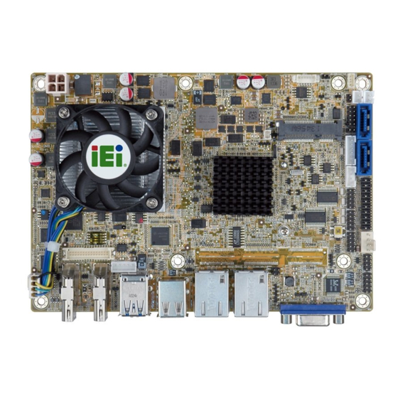
Page 17: Connectors
NANO-QM871-i1 EPIC SBC 1.4 Connectors The connectors on the NANO-QM871-i1 are shown in the figure below. Figure 1-2: Connectors Page 4... -
Page 18: Dimensions
NANO-QM871-i1 EPIC SBC 1.5 Dimensions The main dimensions of the NANO-QM871-i1 are shown in the diagram below. Figure 1-3: NANO-QM871-i1 Dimensions (mm) Page 5... -
Page 19: Data Flow
NANO-QM871-i1 EPIC SBC 1.6 Data Flow Figure 1-4 shows the data flow between the system chipset, the CPU and other components installed on the motherboard. Figure 1-4: Data Flow Diagram Page 6... -
Page 20: Technical Specifications
NANO-QM871-i1 EPIC SBC 1.7 Technical Specifications The NANO-QM871-i1 technical specifications are listed in Table 1-2. Specification NANO-QM871-i1 EPIC Form Factor Standard Intel® mobile Core™ i7-4700EQ processor with Intel® AMT 9.0 support (2.4 GHz, quad-core, 6 MB cache, TDP=47 W) Intel® mobile Core™ i5-4400E processor with Intel® AMT 9.0 support (2.7 GHz, dual-core, 3 MB cache, TDP=37 W) - Page 21 NANO-QM871-i1 EPIC SBC 1 x VGA (up to 1920x1200@60Hz) Display Output 1 x 18/24-bit dual-channel LVDS by CH7511B DP to LVDS converter (up to 1920x1200@60Hz) 2 x HDMI (up to 2500x1600@60Hz) Supports triple independent display with dual HDMI+VGA/ dual HDMI+LVDS/HDMI+VGA+LVDS...
-
Page 22: Table 1-2: Technical Specifications
NANO-QM871-i1 EPIC SBC 12V@4.78A (2.4 GHz Intel® Core™ i7-4700EQ CPU with 4 GB Power Consumption 1333 MHz DDR3 memory) Operating Temperature -10ºC ~ 60ºC Storage Temperature -20ºC ~ 60ºC Operating Humidity 5% ~ 95% (non-condensing) Dimensions 115 mm x 165 mm... -
Page 23: Packing List
NANO-QM871-i1 EPIC SBC Chapter Packing List Page 10... -
Page 24: Anti-Static Precautions
Only handle the edges of the PCB:- Don't touch the surface of the motherboard. Hold the motherboard by the edges when handling. 2.2 Unpacking Precautions When the NANO-QM871-i1 is unpacked, please do the following: Follow the antistatic guidelines above. Make sure the packing box is facing upwards when opening. -
Page 25: Packing List
If any of the components listed in the checklist below are missing, do not proceed with the installation. Contact the IEI reseller or vendor the NANO-QM871-i1 was purchased from or contact an IEI sales representative directly by sending an email to sales@ieiworld.com. -
Page 26: Optional Items
NANO-QM871-i1 EPIC SBC Quantity Item and Part Number Image One Key Recovery CD Quick installation guide Table 2-1: Packing List 2.4 Optional Items These optional items are available. Item and Part Number Image iRIS-1010 module, IPMI 2.0 adapter card with AST1010... -
Page 27: Table 2-2: Optional Items
NANO-QM871-i1 EPIC SBC Item and Part Number Image Infineon TPM module (P/N: TPM-IN01-R11) Table 2-2: Optional Items Page 14... -
Page 28: Connector Pinouts
NANO-QM871-i1 EPIC SBC Chapter Connector Pinouts Page 15... -
Page 29: Peripheral Interface Connectors
NANO-QM871-i1 EPIC SBC 3.1 Peripheral Interface Connectors Section 3.1.1 shows peripheral interface connector locations. Section 3.1.2 lists all the peripheral interface connectors seen in Section 3.1.1. 3.1.1 Layout The figure below shows the on-board peripheral connectors, rear panel peripheral connectors and on-board jumpers. -
Page 30: Peripheral Interface Connectors
NANO-QM871-i1 EPIC SBC 3.1.2 Peripheral Interface Connectors The table below shows a list of the peripheral interface connectors on the NANO-QM871-i1. Detailed descriptions of these connectors can be found below. Connector Type Label Audio connector 10-pin header AUDIO1 Battery connector... -
Page 31: External Interface Panel Connectors
USB 2.0 connector 8-pin header USB1 Table 3-1: Peripheral Interface Connectors 3.1.3 External Interface Panel Connectors The table below lists the rear panel connectors on the NANO-QM871-i1. Detailed descriptions of these connectors can be found in a later section. Connector Type Label... -
Page 32: Battery Connector
NANO-QM871-i1 EPIC SBC The 10-pin audio connector is connected to external audio devices including speakers and microphones for the input and output of audio signals to and from the system. Figure 3-2: Audio Connector Location Description Description SPK_OUT-R LINE_IN-R SPK_OUT-L... -
Page 33: Chassis Intrusion Connector
NANO-QM871-i1 EPIC SBC CN Location: See Figure 3-3 CN Pinouts: See Table 3-4 This is connected to the system battery. The battery provides power to the system clock to retain the time when power is turned off. Figure 3-3: Battery Connector Location... -
Page 34: Digital I/O Connector
NANO-QM871-i1 EPIC SBC Figure 3-4: Chassis Intrusion Connector Location Description Pull High +3.3V CHASSIS OPEN Table 3-5: Chassis Intrusion Connector Pinouts 3.2.4 Digital I/O Connector CN Label: DIO1 CN Type: 10-pin header CN Location: See Figure 3-5 CN Pinouts: See Table 3-6 The digital I/O connector provides programmable input and output for external devices. -
Page 35: Fan Connector (Cpu)
NANO-QM871-i1 EPIC SBC Description Description DOUT3 DOUT2 DOUT1 DOUT0 DIN3 DIN2 DIN1 DIN0 Table 3-6: Digital I/O Connector Pinouts 3.2.5 Fan Connector (CPU) CN Label: CPU_FAN1 CN Type: 4-pin wafer CN Location: See Figure 3-6 CN Pinouts: See Table 3-7 The fan connector attaches to a CPU cooling fan. -
Page 36: Fan Connector (System)
NANO-QM871-i1 EPIC SBC 3.2.6 Fan Connector (System) CN Label: SYS_FAN1 4-pin wafer CN Type: CN Location: See Figure 3-7 CN Pinouts: See Table 3-8 The fan connector attaches to a system cooling fan. Figure 3-7: System Fan Connector Location Description... -
Page 37: Ipmi Active Led Connector
NANO-QM871-i1 EPIC SBC Figure 3-8: Front Panel Connector Location Description Description PWR_LED+ PWRBTN_SW# PWR_LED- HDD_LED+ EXTRST- HDD_LED- Table 3-9: Front Panel Connector Pinouts 3.2.8 IPMI Active LED Connector CN Label: LEDCN1 CN Type: 2-pin header CN Location: See Figure 3-9... -
Page 38: Iris Module Slot
The iRIS module slot allows installation of the iRIS-1010 module. WARNING: The iRIS module slot is designed to install the iRIS-1010 module only. DO NOT install other modules into the iRIS module slot. Doing so may cause damage to the NANO-QM871-i1. Page 25... -
Page 39: Keyboard And Mouse Connector
NANO-QM871-i1 EPIC SBC Figure 3-10: iRIS Module Slot Location 3.2.10 Keyboard and Mouse Connector CN Label: KB_MS1 6-pin wafer CN Type: CN Location: See Figure 3-11 CN Pinouts: See Table 3-11 The keyboard and mouse connector connects to a PS/2 Y-cable that can be connected to a PS/2 keyboard and mouse. -
Page 40: Lan Active Led Connector
NANO-QM871-i1 EPIC SBC Description Keyboard Clock Table 3-11: Keyboard and Mouse Connector Pinouts 3.2.11 LAN Active LED Connector CN Label: LAN_ACT_LED1 CN Type: 4-pin header CN Location: See Figure 3-12 CN Pinouts: See Table 3-12 The connector is for active LED connection of the external LAN ports. -
Page 41: Figure 3-13: Lvds Connector Location
NANO-QM871-i1 EPIC SBC CN Location: See Figure 3-13 CN Pinouts: See Table 3-13 The LVDS connector is for an LCD panel connected to the board. Figure 3-13: LVDS Connector Location Description Description LVDS_A_TX0-P LVDS_A _TX0-N LVDS_A_TX1-P LVDS_A _TX1-N LVDS_A_TX2-P LVDS_A _TX2-N... -
Page 42: Lvds Backlight Connector
NANO-QM871-i1 EPIC SBC 3.2.13 LVDS Backlight Connector CN Label: INV1 CN Type: 5-pin wafer CN Location: See Figure 3-14 CN Pinouts: See Table 3-14 The backlight inverter connector provides power to the LCD panel connected to the board. Figure 3-14: LVDS Backlight Inverter Connector... -
Page 43: Figure 3-15: Pcie Mini Card Slot Location
NANO-QM871-i1 EPIC SBC The PCIe Mini card slot enables a PCIe Mini card expansion module to be connected to the board. Cards supported include among others PCIe Mini cards and mSATA cards. Figure 3-15: PCIe Mini Card Slot Location Description... -
Page 44: Power Connector (12V)
NANO-QM871-i1 EPIC SBC Description Description SATA_DET4_R_N 1.5V MSATA_SEL# VCC3 Table 3-15: PCIe Mini Card Slot Pinouts 3.2.15 Power Connector (12V) CN Label: PWR1 CN Type: 4-pin connector CN Location: See Figure 3-16 CN Pinouts: See Table 3-16 The power connector is connected to an external power supply and supports 12V power input. -
Page 45: Serial Port Connectors
NANO-QM871-i1 EPIC SBC 3.2.16 RS-232 Serial Port Connectors CN Label: COM1, COM2 10-pin header CN Type: CN Location: See Figure 3-17 CN Pinouts: See Table 3-17 The 10-pin serial port connector provides one RS-232 serial communication channel. The COM serial port connector can be connected to an external RS-232 serial port device. -
Page 46: Sata 6Gb/S Drive Connectors
NANO-QM871-i1 EPIC SBC This connector provides RS-422 or RS-485 communications. Figure 3-18: RS-422/485 Serial Port Connector Location Description RXD422- RXD422+ TXD422+/TXD485+ TXD422-/TXD485- Table 3-18: RS-422/485 Serial Port Connector Pinouts Use the optional RS-422/485 cable to connect to a serial device. The pinouts of the DB-9 connector are listed below. -
Page 47: Sata Power Connectors
NANO-QM871-i1 EPIC SBC The SATA connectors connect to SATA hard drives or optical drives with data transfer speeds as high as 6Gb/s. Figure 3-19: SATA 6Gb/s Drive Connector Locations Description Table 3-20: SATA 6Gb/s Drive Connector Pinouts 3.2.19 SATA Power Connectors... -
Page 48: Smbus Connector
NANO-QM871-i1 EPIC SBC Figure 3-20: SATA Power Connector Locations Description +V5S Table 3-21: SATA Power Connector Pinouts 3.2.20 SMBus Connector CN Label: SMB1 CN Type: 4-pin wafer CN Location: See Figure 3-21 CN Pinouts: See Table 3-22 The SMBus (System Management Bus) connector provides low-speed system management communications. -
Page 49: So-Dimm Connector
NANO-QM871-i1 EPIC SBC Figure 3-21: SMBus Connector Location Description SMB_DATA SMB_CLK +V5S Table 3-22: SMBus Connector Pinouts 3.2.21 SO-DIMM Connector CN Label: DIMM1 CN Type: 204-pin DDR3 SO-DIMM connector See Figure 3-22 CN Location: The SO-DIMM connector is for installing memory on the system. -
Page 50: Spi Flash Connector
NANO-QM871-i1 EPIC SBC Figure 3-22: SO-DIMM Connector Locations 3.2.22 SPI Flash Connector CN Label: SPI1 CN Type: 6-pin wafer CN Location: See Figure 3-23 CN Pinouts: See Table 3-23 The 6-pin SPI Flash connector is used to flash the BIOS. -
Page 51: Spi Flash Connector (Ec)
NANO-QM871-i1 EPIC SBC Description SPI_CLK_SW SPI_SI_SW Table 3-23: SPI Flash Connector Pinouts 3.2.23 SPI Flash Connector (EC) CN Label: 2-pin header CN Type: CN Location: See Figure 3-24 CN Pinouts: See Table 3-24 The 2-pin EC SPI flash connector is used to flash the EC BIOS. -
Page 52: Usb 2.0 Connector
NANO-QM871-i1 EPIC SBC The Trusted Platform Module (TPM) connector secures the system on bootup. Figure 3-25: TPM Connector Location Description Description LCLK LFRAME# LRERST# LAD3 LAD2 LAD1 LAD0 SB3V SERIRQ GLKRUN# LPCPD# LDRQ# Table 3-25: TPM Connector Pinouts 3.2.25 USB 2.0 Connector... -
Page 53: External Interface Connectors
DATA- DATA+ DATA+ DATA- Table 3-26: USB Port Connector Pinouts 3.3 External Interface Connectors The NANO-QM871-i1 on-board external interface connectors are shown in Figure 3-27. Figure 3-27: External Interface Connectors 3.3.1 Ethernet Connectors CN Label: LAN1, LAN2 CN Type: RJ-45 connector... -
Page 54: Hdmi Connectors
NANO-QM871-i1 EPIC SBC The NANO-QM871-i1 is equipped with two built-in RJ-45 Ethernet controllers. Each controller can connect to the LAN through one RJ-45 LAN connector. DESCRIPTION DESCRIPTION MDIA0+ MDIA2- MDIA0- MDIA1- MDIA1+ MDIA3+ MDIA2+ MDIA3- Table 3-27: LAN Pinouts Figure 3-28: Ethernet Connector... -
Page 55: Usb 2.0 Connector
NANO-QM871-i1 EPIC SBC Description Description HDMI_DATA2#- HDMI_DATA1+ HDMI_SCL HDMI_DATA1#- HDMI_SDA HDMI_DATA0+ +5VCC HDMI_DATA0#- HDMI_HPD HDMI_CLK+ Table 3-29: HDMI Connector Pinouts Figure 3-29: HDMI Connector 3.3.3 USB 2.0 Connector CN Label: USB_CON2 CN Type: Dual USB 2.0 port See Figure 3-27... -
Page 56: Usb 3.0 Connector
Dual USB 3.0 port CN Type: CN Location: See Figure 3-27 CN Pinouts: See Table 3-31 The NANO-QM871-i1 has two external USB 3.0 ports. Each USB 3.0 port can be connected to a USB device. Description VBUS GND1 STDA_SSRX1_N STDA_SSRX1_P... -
Page 57: Figure 3-30: Vga Connector
NANO-QM871-i1 EPIC SBC Figure 3-30: VGA Connector Description Description GREEN GROUND BLUE DDCDAT HSYNC VSYNC DDCCLK Table 3-32: VGA Connector Pinouts Page 44... -
Page 58: Installation
NANO-QM871-i1 EPIC SBC Chapter Installation Page 45... -
Page 59: Anti-Static Precautions
Electrostatic discharge (ESD) can cause serious damage to electronic components, including the NANO-QM871-i1. Dry climates are especially susceptible to ESD. It is therefore critical to strictly adhere to the following anti-static precautions whenever the NANO-QM871-i1, or any other electrical component, is handled. - Page 60 NANO-QM871-i1 EPIC SBC WARNING: The installation instructions described in this manual should be carefully followed in order to prevent damage to the NANO-QM871-i1, NANO-QM871-i1 components and injury to the user. Before and during the installation please DO the following: Read the user manual: The user manual provides a complete description of the installation instructions and configuration options.
-
Page 61: Cooling Kit Installation
NANO-QM871-i1 EPIC SBC 4.3 Cooling Kit Installation An IEI CPU cooling kit can be purchased separately (See Chapter 2). The cooling kit is comprised of a CPU heat sink and a cooling fan. WARNING: Do not wipe off (accidentally or otherwise) the pre-sprayed layer of thermal paste on the bottom of the heat sink. -
Page 62: Figure 4-2: Align The Cooling Kit
NANO-QM871-i1 EPIC SBC Step 2: Properly orient the cooling kit. The CPU fan cable must not interfere with the fan or other moving parts. Make sure the cable can be routed away from the moving parts. Step 3: Properly align the cooling kit. Line up the four screws with the screw holes on the support bracket below the board (Figure 4-2). -
Page 63: So-Dimm Installation
4.4 SO-DIMM Installation WARNING: Using incorrectly specified SO-DIMM may cause permanent damage to the NANO-QM871-i1. Please make sure the purchased SO-DIMM complies with the memory specifications of the NANO-QM871-i1. SO-DIMM specifications compliant with the NANO-QM871-i1 are listed in Chapter 1. -
Page 64: Iris-1010 Module Installation
NANO-QM871-i1 EPIC SBC Figure 4-4: SO-DIMM Installation Step 1: Locate the SO-DIMM socket. Place the NANO-QM871-i1 on an anti-static pad with the solder side facing up. Step 2: Align the SO-DIMM with the socket. Align the notch on the memory with the notch on the memory socket. -
Page 65: Figure 4-5: Removing The Retention Screw For The Iris-1010 Module
NANO-QM871-i1 EPIC SBC Figure 4-5: Removing the Retention Screw for the iRIS-1010 Module Step 3: Insert into the slot at an angle. Line up the notch on the module with the notch on the slot. Slide the iRIS-1010 module into the slot at an angle of about 20º... -
Page 66: Pcie Mini Card Installation
After installing the iRIS-1010 module, use LAN2 port to establish a network connection. 4.6 PCIe Mini Card Installation One PCIe Mini card slot is located on the NANO-QM871-i1. To install the PCIe Mini card, please refer to the diagram and instructions below. Step 1: Locate the PCIe Mini card slot. -
Page 67: Figure 4-8: Removing The Retention Screw
NANO-QM871-i1 EPIC SBC Figure 4-8: Removing the Retention Screw Step 3: Insert into the socket at an angle. Line up the notch on the card with the notch on the slot. Slide the PCIe Mini card into the socket at an angle of about 20º... -
Page 68: System Configuration
Jumper Location: See Figure 4-11 Set the switch to select AT or ATX power mode for the NANO-QM871-i1. AT power mode limits the system to on/off. ATX allows the system to use various power saving states and enter a standby state, so the system can be turned on remotely over a network. To configure, see the diagram below. -
Page 69: Clear Cmos
Jumper Location: See Figure 4-12 If the NANO-QM871-i1 fails to boot due to improper BIOS settings, the clear CMOS button clears the CMOS data and resets the system BIOS information. To do this, push the clear CMOS button for three seconds, then restart the system. -
Page 70: Lvds Voltage Selection
NANO-QM871-i1 EPIC SBC Figure 4-12: Clear CMOS Jumper Location 4.7.3 LVDS Voltage Selection Jumper Label: Jumper Type: 3-pin header See Table 4-1 Jumper Settings: Jumper Location: See Figure 4-13 Selects the voltage of the LVDS connector. Description Short 1-2 +3.3 V (Default) -
Page 71: Lvds Resolution Selection
NANO-QM871-i1 EPIC SBC 4.7.4 LVDS Resolution Selection Jumper Label: DIP switch Jumper Type: Jumper Settings: See Table 4-2 Jumper Location: See Figure 4-14 Selects the resolution of the LCD panel connected to the LVDS connector. * ON=0, OFF=1; S= Single, D=Dual... -
Page 72: Chassis Installation
The chassis should have fans and vents as necessary to keep things cool. The NANO-QM871-i1 must be installed in a chassis with ventilation holes on the sides allowing airflow to travel through the heat sink surface. In a system with an individual power supply unit, the cooling fan of a power supply can also help generate airflow through the board surface. -
Page 73: Internal Peripheral Device Connections
4.9 Internal Peripheral Device Connections This section outlines the installation of peripheral devices to the onboard connectors. 4.9.1 AT/ATX Power Connection Follow the instructions below to connect the NANO-QM871-i1 to an AT or ATX power supply. WARNING: Disconnect the power supply power cord from its AC power source to prevent a sudden power surge to the NANO-QM871-i1. -
Page 74: Audio Kit Installation
The Audio Kit that came with the NANO-QM871-i1 connects to the 10-pin audio connector on the NANO-QM871-i1. The audio kit consists of three audio jacks. One audio jack, Mic In, connects to a microphone. The remaining two audio jacks, Line-In and Line-Out, connect to two speakers. -
Page 75: Lvds Lcd Installation
4.9.3 LVDS LCD Installation The NANO-QM871-i1 can be connected to a TFT LCD screen through the LVDS crimp connectors on the board. To connect a TFT LCD to the NANO-QM871-i1, please follow the steps below. -
Page 76: Figure 4-18: Lvds Connector
NANO-QM871-i1 EPIC SBC WARNING: The diagram below is merely for illustration. The configuration and connection of the cables from the TFT LCD screen being installed may be different. Please refer to the installation manual that came with the TFT LCD screen. -
Page 77: Sata Drive Connection
NANO-QM871-i1 EPIC SBC Figure 4-19: Backlight Inverter Connection 4.9.4 SATA Drive Connection The NANO-QM871-i1 is shipped with two SATA drive cables. To connect the SATA drive to the connector, please follow the steps below. Step 1: Locate the SATA connector and the SATA power connector. The locations of the connectors are shown in Chapter 3. -
Page 78: Single Rs-232 Cable
NANO-QM871-i1 EPIC SBC Figure 4-20: SATA Drive Cable Connection Step 3: Connect the cable to the SATA disk. Connect the connector on the other end of the cable to the connector at the back of the SATA drive. See Figure 4-20. -
Page 79: External Peripheral Interface Connection
4.10.1 HDMI Display Device Connection The HDMI connector transmits a digital signal to compatible HDMI display devices such as a TV or computer screen. To connect the HDMI cable to the NANO-QM871-i1, follow the steps below. Step 1: Locate the HDMI connectors. -
Page 80: Lan Connection
Locate the RJ-45 connectors. The locations of the RJ-45 connectors are shown in Chapter 3. Step 2: Align the connectors. Align the RJ-45 connector on the LAN cable with one of the RJ-45 connectors on the NANO-QM871-i1. See Figure 4-23. Page 67... -
Page 81: Usb Connection (Dual Connector)
4.10.3 USB Connection (Dual Connector) The external USB 2.0/3.0 connectors provide easier and quicker access to external USB devices. Follow the steps below to connect USB devices to the NANO-QM871-i1. Step 1: Locate the USB 2.0/3.0 connectors. The locations of the USB 2.0/3.0 connectors are shown in Chapter 3. -
Page 82: Vga Monitor Connection
Figure 4-24: USB Connector 4.10.4 VGA Monitor Connection The NANO-QM871-i1 has a single female DB-15 connector on the external peripheral interface panel. The DB-15 connector is connected to a CRT or VGA monitor. To connect a monitor to the NANO-QM871-i1, please follow the instructions below. -
Page 83: Intel® Amt Setup Procedure
Step 0: 4.11 Intel® AMT Setup Procedure The NANO-QM871-i1 is featured with the Intel® Active Management Technology (AMT). To enable the Intel® AMT function, follow the steps below. Step 1: Make sure the DIMM1 socket is installed with one DDR3 SO-DIMM. - Page 84 NANO-QM871-i1 EPIC SBC process. Enter the Intel® current ME password as it requires (the Intel® default password is admin). Step 0: NOTE: To change the password, enter a new password following the strong password rule (containing at least one upper case letter, one lower case letter, one digit and one special character, and be at least eight characters).
-
Page 85: Bios
NANO-QM871-i1 EPIC SBC Chapter BIOS Page 72... -
Page 86: Introduction
NANO-QM871-i1 EPIC SBC 5.1 Introduction The BIOS is programmed onto the BIOS chip. The BIOS setup program allows changes to certain system settings. This chapter outlines the options that can be changed. NOTE: Some of the BIOS options may vary throughout the life cycle of the product and are subject to change without prior notice. -
Page 87: Getting Help
NANO-QM871-i1 EPIC SBC Function Decrease the numeric value or make changes Page Up key Move to the next page Page Dn key Move to the previous page Esc key Main Menu – Quit and not save changes into CMOS Status Page Setup Menu and Option Page Setup Menu --... - Page 88 NANO-QM871-i1 EPIC SBC Security – Sets User and Supervisor Passwords. Save & Exit – Selects exit options and loads default settings. The following sections completely describe the configuration options found in the menu items at the top of the BIOS screen and listed above.
-
Page 89: Main
NANO-QM871-i1 EPIC SBC 5.2 Main The Main BIOS menu (BIOS Menu 1) appears when the BIOS Setup program is entered. The Main menu gives an overview of the basic system information. Aptio Setup Utility – Copyright (C) 2012 American Megatrends, Inc. -
Page 90: Advanced
NANO-QM871-i1 EPIC SBC System Overview The BIOS Information lists a brief summary of the BIOS. The fields in BIOS Information cannot be changed. The items shown in the system overview include: BIOS Information Processor Information Memory Information PCH Information SPI Clock Frequency... -
Page 91: Acpi Settings
NANO-QM871-i1 EPIC SBC Aptio Setup Utility – Copyright (C) 2012 American Megatrends, Inc. Main Advanced Chipset Boot Security Save & Exit > ACPI Settings System ACPI Parameters > RTC Wake Settings > Trusted Computing > CPU Configuration ---------------------- > SATA Configuration >... -
Page 92: Rtc Wake Settings
NANO-QM871-i1 EPIC SBC ACPI Sleep State [S1 only (CPU Stop Clock)] Use the ACPI Sleep State option to specify the sleep state the system enters when it is not being used. S1 only (CPU Stop The system enters S1 (POS) sleep state. The... - Page 93 NANO-QM871-i1 EPIC SBC Wake system with Fixed Time [Disabled] Use the Wake system with Fixed Time option to enable or disable the system wake on alarm event. Disabled The real time clock (RTC) cannot generate a wake EFAULT event Enabled...
-
Page 94: Trusted Computing
NANO-QM871-i1 EPIC SBC 5.3.3 Trusted Computing Use the Trusted Computing menu (BIOS Menu 5) to configure settings related to the Trusted Computing Group (TCG) Trusted Platform Module (TPM). Aptio Setup Utility – Copyright (C) 2012 American Megatrends, Inc. Advanced Configuration... -
Page 95: Cpu Configuration
NANO-QM871-i1 EPIC SBC 5.3.4 CPU Configuration Use the CPU Configuration menu (BIOS Menu 6) to view detailed CPU specifications and configure the CPU. Aptio Setup Utility – Copyright (C) 2012 American Megatrends, Inc. Advanced CPU Configuration Enabled for Windows XP and Linux (OS optimized Intel(R) Celeron(R) CPU 2002E @ 1.50GHz... - Page 96 NANO-QM871-i1 EPIC SBC Intel VT-x Technology: Indicates if Intel VT-x Technology is supported by the CPU. Intel SMX Technology: Indicates if Intel SMX Technology is supported by the CPU. EIST Technology: Indicates if the Enhanced Intel SpeedStep® Technology (EIST) is supported by the CPU.
-
Page 97: Sata Configuration
NANO-QM871-i1 EPIC SBC 5.3.5 SATA Configuration Use the SATA Configuration menu (BIOS Menu 7) to change and/or set the configuration of the SATA devices installed in the system. Aptio Setup Utility – Copyright (C) 2012 American Megatrends, Inc. Advanced SATA Controller(s) -
Page 98: Intel(R) Rapid Start Technology
NANO-QM871-i1 EPIC SBC NOTE: Before accessing the RAID configuration utility, ensure to set the Option ROM Messages BIOS option in the Boot menu to Force BIOS. This is to allow the “Press <CTRL+I> to enter Configuration Utility……” message to appear during POST. Press Ctrl+I when prompted to enter the RAID configuration utility. -
Page 99: Amt Configuration
NANO-QM871-i1 EPIC SBC 5.3.7 AMT Configuration The AMT Configuration menu (BIOS Menu 9) allows the Intel® AMT options to be configured. Aptio Setup Utility – Copyright (C) 2012 American Megatrends, Inc. Advanced Intel AMT [Enabled] Enable/Disable Intel (R) Un-Configure ME... -
Page 100: Usb Configuration
NANO-QM871-i1 EPIC SBC 5.3.8 USB Configuration Use the USB Configuration menu (BIOS Menu 10) to read USB configuration information and configure the USB settings. Aptio Setup Utility – Copyright (C) 2012 American Megatrends, Inc. Advanced USB Configuration Enables Legacy USB support. -
Page 101: Iwdd H/W Monitor
NANO-QM871-i1 EPIC SBC Enabled Legacy USB support enabled EFAULT Legacy USB support disabled Disabled Auto Legacy USB support disabled if no USB devices are connected 5.3.9 iWDD H/W Monitor The iWDD H/W Monitor menu (BIOS Menu 11) displays the CPU temperature and CPU fan speed, and contains the fan configuration submenu. -
Page 102: Bios Menu 12: Smar Fan Mode Configuration
NANO-QM871-i1 EPIC SBC Aptio Setup Utility – Copyright (C) 2012 American Megatrends, Inc. Advanced Smart Fan Mode Configuration Smart Fan Mode Select CPU_FAN1 Smart Fan Control [Auto Mode] Auto mode fan start temperature 50 Auto mode fan off temperature ---------------------... -
Page 103: F81866 Super Io Configuration
NANO-QM871-i1 EPIC SBC Auto mode fan slope PWM Use the + or – key to change the Auto mode fan slope PWM value. Enter a decimal number between 1 and 64. 5.3.10 F81866 Super IO Configuration Use the F81866 Super IO Configuration menu (BIOS Menu 13) to set or change the configurations for the serial ports. -
Page 104: Serial Port N Configuration
NANO-QM871-i1 EPIC SBC 5.3.10.1 Serial Port n Configuration Use the Serial Port n Configuration menu (BIOS Menu 14) to configure the serial port n. Aptio Setup Utility – Copyright (C) 2012 American Megatrends, Inc. Advanced Serial Port n Configuration Enable or Disable Serial... - Page 105 NANO-QM871-i1 EPIC SBC IO=3F8h; Serial Port I/O port address is 3F8h and the interrupt IRQ=3, 4 address is IRQ3, 4 Serial Port I/O port address is 2F8h and the interrupt IO=2F8h; address is IRQ3, 4 IRQ=3, 4 IO=2C0h; Serial Port I/O port address is 2C0h and the interrupt...
- Page 106 NANO-QM871-i1 EPIC SBC IO=2C8h; Serial Port I/O port address is 2C8h and the interrupt IRQ=3, 4 address is IRQ3, 4 5.3.10.1.3 Serial Port 3 Configuration Serial Port [Enabled] Use the Serial Port option to enable or disable the serial port.
-
Page 107: Serial Port Console Redirection
NANO-QM871-i1 EPIC SBC 5.3.11 Serial Port Console Redirection The Serial Port Console Redirection menu (BIOS Menu 15) allows the console redirection options to be configured. Console redirection allows users to maintain a system remotely by re-directing keyboard input and text output through the serial port. - Page 108 NANO-QM871-i1 EPIC SBC Terminal Type [ANSI] Use the Terminal Type option to specify the remote terminal type. The target terminal type is VT100 VT100 VT100+ The target terminal type is VT100+ VT-UTF8 The target terminal type is VT-UTF8 ANSI The target terminal type is ANSI...
- Page 109 NANO-QM871-i1 EPIC SBC Even The parity bit is 0 if the number of ones in the data bits is even. The parity bit is 0 if the number of ones in the data bits is odd. Mark The parity bit is always 1. This option does not provide error detection.
-
Page 110: Iei Feature
NANO-QM871-i1 EPIC SBC 5.3.12 iEi Feature Use the iEi Feature menu (BIOS Menu 16) to configure One Key Recovery function. Aptio Setup Utility – Copyright (C) 2012 American Megatrends, Inc. Advanced iEi Feature Auto Recovery Function Reboot and recover Auto Recovery Function... -
Page 111: Chipset
NANO-QM871-i1 EPIC SBC 5.4 Chipset Use the Chipset menu (BIOS Menu 17) to access the PCH IO and System Agent (SA) configuration menus. WARNING! Setting the wrong values for the Chipset BIOS selections in the Chipset BIOS menu may cause the system to malfunction. -
Page 112: Pch-Io Configuration
NANO-QM871-i1 EPIC SBC 5.4.1 PCH-IO Configuration Use the PCH-IO Configuration menu (BIOS Menu 18) to configure the PCH parameters. Aptio Setup Utility – Copyright (C) 2012 American Megatrends, Inc. Chipset Auto Power Button Status [Enable (AT)] Control Detection of the Azalia device. -
Page 113: Pci Express Configuration
NANO-QM871-i1 EPIC SBC USB Power SW1 [+5V DUAL] Use the USB Power SW1 BIOS option to configure the power of USB port by software. Sets to +5V +5V DUAL Sets to +5V DUAL EFAULT 5.4.1.1 PCI Express Configuration Use the PCI Express Configuration menu (BIOS Menu 19) to select the support type of the PCI Express or PCIe Mini slots. -
Page 114: System Agent (Sa) Configuration
NANO-QM871-i1 EPIC SBC Detect Non-Compliance Device [Disabled] Use the Detect Non-Compliance Device option to enable or disable the “detect no-compliance PCIe device” function. Disabled Detect no-compliance PCIe device function is disabled EFAULT Detect no-compliance PCIe device function is enabled. If Enabled will take more time at POST if it is enabled. -
Page 115: Bios Menu 21: Graphics Configuration
NANO-QM871-i1 EPIC SBC Aptio Setup Utility – Copyright (C) 2012 American Megatrends, Inc. Chipset Graphics Configuration Select which of Primary Display [Auto] IGFX/PEG/PCI Graphics DVMT Pre-Allocated [256M] device should be Primary DVMT Total Gfx Mem [MAX] Display Or select SG for Switchable Gfx. -
Page 116: Memory Configuration
NANO-QM871-i1 EPIC SBC DVMT Total Gfx Mem [MAX] Use the DVMT Total Gfx Mem option to select DVMT5.0 total graphic memory size used by the internal graphic device. The following options are available: 128M 256M Default Primary IGFX Boot Display [VBIOS Default] Use the Primary IGFX Boot Display option to select the display device used by the system when it boots. -
Page 117: Boot
NANO-QM871-i1 EPIC SBC Aptio Setup Utility – Copyright (C) 2012 American Megatrends, Inc. Chipset Memory Information Memory Frequency 1600 Mhz Total Memory 4096 MB (DDR3) DIMM1 4096 MB (DDR3) --------------------- : Select Screen ↑ ↓: Select Item Enter: Select +/-: Change Opt. - Page 118 NANO-QM871-i1 EPIC SBC Allows the Number Lock on the keyboard to be EFAULT enabled automatically when the computer system boots up. This allows the immediate use of the 10-key numeric keypad located on the right side of the keyboard. To confirm this, the Number Lock LED light on the keyboard is lit.
-
Page 119: Security
NANO-QM871-i1 EPIC SBC UEFI Boot [Disabled] Use the UEFI Boot BIOS option to allow the system to boot from the UEFI devices. Disabled Disables to boot from the UEFI devices. EFAULT Enabled Enables to boot from the UEFI devices. 5.6 Security Use the Security menu (BIOS Menu 24) to set system and user passwords. -
Page 120: Save & Exit
NANO-QM871-i1 EPIC SBC 5.7 Save & Exit Use the Save & Exit menu (BIOS Menu 25) to load default BIOS values, optimal failsafe values and to save configuration changes. Aptio Setup Utility – Copyright (C) 2012 American Megatrends, Inc. Main... -
Page 121: Software Drivers
NANO-QM871-i1 EPIC SBC Chapter Software Drivers Page 108... -
Page 122: Available Software Drivers
NANO-QM871-i1 EPIC SBC 6.1 Available Software Drivers NOTE: The content of the CD may vary throughout the life cycle of the product and is subject to change without prior notice. Visit the IEI website or contact technical support for the latest updates. -
Page 123: Figure 6-1: Start Up Screen
NANO-QM871-i1 EPIC SBC Figure 6-1: Start Up Screen Step 3: Click NANO-QM871. Step 4: The list of drivers in Figure 6-2 appears. Figure 6-2: Drivers Page 110... -
Page 124: Chipset Driver Installation
NANO-QM871-i1 EPIC SBC 6.3 Chipset Driver Installation To install the chipset driver, please do the following. Step 1: Access the driver list. (See Section 6.2) Step 2: Click “1-Chipset”. Step 3: Locate the setup file and double click on it. -
Page 125: Figure 6-4: Chipset Driver License Agreement
NANO-QM871-i1 EPIC SBC Figure 6-4: Chipset Driver License Agreement Step 8: The Read Me file in Figure 6-5 appears. Step 9: Click Next to continue. Figure 6-5: Chipset Driver Read Me File Page 112... -
Page 126: Figure 6-6: Chipset Driver Setup Operations
NANO-QM871-i1 EPIC SBC Step 10: Setup Operations are performed as shown in Figure 6-6. Figure 6-6: Chipset Driver Setup Operations Step 11: Once the Setup Operations are complete, click Next to continue. Step 12: The Finish screen in Figure 6-7 appears. -
Page 127: Graphics Driver Installation
NANO-QM871-i1 EPIC SBC Figure 6-7: Chipset Driver Installation Finish Screen 6.4 Graphics Driver Installation To install the graphics driver, please do the following. Step 1: Access the driver list. (See Section 6.2) Step 2: Click “2-Graphics” and select the folder which corresponds to the operating system. -
Page 128: Figure 6-8: Graphics Driver Welcome Screen
NANO-QM871-i1 EPIC SBC Figure 6-8: Graphics Driver Welcome Screen Step 5: The license agreement in Figure 6-9 appears. Read the License Agreement. Step 6: Click Yes to continue. Figure 6-9: Graphics Driver License Agreement Page 115... -
Page 129: Figure 6-10: Graphics Driver Read Me File
NANO-QM871-i1 EPIC SBC Step 7: The Read Me file in Figure 6-10 appears. Step 8: Click Next to continue. Figure 6-10: Graphics Driver Read Me File Step 9: Setup Operations are performed as shown in Figure 6-11. Figure 6-11: Graphics Driver Setup Operations... -
Page 130: Lan Driver Installation
NANO-QM871-i1 EPIC SBC Step 10: Once the Setup Operations are complete, click the Next icon to continue. Step 11: The Finish screen appears. Step 12: Select “Yes, I want to restart the computer now” and click the Finish icon. See Figure 6-12. -
Page 131: Figure 6-13: Windows Control Panel
NANO-QM871-i1 EPIC SBC Figure 6-13: Windows Control Panel Step 2: The system control panel window in Figure 6-14 appears. Step 3: Click the Device Manager link (Figure 6-14). Figure 6-14: System Control Panel Step 4: A list of system hardware devices appears (Figure 6-15). -
Page 132: Figure 6-15: Device Manager List
NANO-QM871-i1 EPIC SBC Step 6: Select Update Driver Software. Figure 6-15: Device Manager List Step 7: The Update Driver Software Window appears (Figure 6-16). Page 119... -
Page 133: Figure 6-16: Update Driver Software Window
NANO-QM871-i1 EPIC SBC Figure 6-16: Update Driver Software Window Step 8: Select “Browse my computer for driver software” and click N to continue. Step 9: Click Browse to select “X:\3-LAN” directory in the Locate File window, where “X:\” is the system CD drive. (Figure 6-17). -
Page 134: Figure 6-18: Lan Driver Installation
NANO-QM871-i1 EPIC SBC Step 11: Driver Installation is performed as shown in Figure 6-18. Figure 6-18: LAN Driver Installation Step 12: The Finish screen in Figure 6-19 appears. Click Close to exit. Figure 6-19: LAN Driver Installation Complete Page 121... -
Page 135: Usb 3.0 Driver Installation
NANO-QM871-i1 EPIC SBC 6.6 USB 3.0 Driver Installation WARNING: Do not run this driver’s installer (Setup.exe) from a USB storage device (ie. external USB hard drive or USB thumb drive). For proper installation, please copy driver files to a local hard drive folder and run from there. -
Page 136: Figure 6-21: Usb 3.0 Driver License Agreement
NANO-QM871-i1 EPIC SBC Step 6: The license agreement in Figure 6-21 appears. Step 7: Read the License Agreement. Step 8: Click Yes to continue. Figure 6-21: USB 3.0 Driver License Agreement Step 9: The Read Me file in Figure 6-22 appears. -
Page 137: Figure 6-23: Usb 3.0 Driver Setup Operations
NANO-QM871-i1 EPIC SBC Step 11: Setup Operations are performed as shown in Figure 6-23. Step 12: Once the Setup Operations are complete, click Next to continue. Figure 6-23: USB 3.0 Driver Setup Operations Step 13: The Finish screen in Figure 6-24 appears. -
Page 138: Audio Driver Installation
NANO-QM871-i1 EPIC SBC 6.7 Audio Driver Installation To install the Audio driver, please do the following. Step 1: Access the driver list. (See Section 6.2) Step 2: Click “5-Audio” and select the folder which corresponds to the operating system. Step 3: Double click the setup file. -
Page 139: Figure 6-26: Audio Driver Installation
NANO-QM871-i1 EPIC SBC Figure 6-26: Audio Driver Installation Step 8: When the driver installation is complete, the screen in Figure 6-27 appears. Figure 6-27: Audio Driver Installation Complete Step 9: Select “Yes, I want to restart my computer now” and click Finish. -
Page 140: Intel® Amt Driver Installation
NANO-QM871-i1 EPIC SBC 6.8 Intel® AMT Driver Installation To install these Intel® AMT components, please do the following. Step 1: Access the driver list. (See Section 6.2) Step 2: Click “7-iAMT Driver & Utility”. Step 3: Locate the setup file and double click it. -
Page 141: Figure 6-29: Intel® Me Driver License Agreement
NANO-QM871-i1 EPIC SBC Figure 6-29: Intel® ME Driver License Agreement Step 9: Setup Operations are performed as shown in Figure 6-30. Step 10: Once the Setup Operations are complete, click Next to continue. Figure 6-30: Intel® ME Driver Setup Operations Step 11: The Finish screen in Figure 6-31 appears. -
Page 142: Figure 6-31: Intel® Me Driver Installation Finish Screen
NANO-QM871-i1 EPIC SBC Step 12: Select “Yes, I want to restart this computer now” and click Finish.Step 0: Figure 6-31: Intel® ME Driver Installation Finish Screen Page 129... -
Page 143: Abios Options
NANO-QM871-i1 EPIC SBC Appendix BIOS Options Page 130... - Page 144 NANO-QM871-i1 EPIC SBC Below is a list of BIOS configuration options in the BIOS chapter. System Overview .........................77 System Date [xx/xx/xx] ......................77 System Time [xx:xx:xx] .......................77 ACPI Sleep State [S1 only (CPU Stop Clock)]..............79 Wake system with Fixed Time [Disabled]................80 ...
- Page 145 NANO-QM871-i1 EPIC SBC Auto Recovery Function [Disabled]...................97 Azalia (HD Audio) [Enabled] ....................99 Power Saving Function [Disabled]..................99 USB Power SW1 [+5V DUAL]................... 100 PCIe Speed [Auto]......................100 Detect Non-Compliance Device [Disabled] ..............101 Primary Display [Auto] ..................... 102 ...
-
Page 146: B Terminology
NANO-QM871-i1 EPIC SBC Appendix Terminology Page 133... - Page 147 NANO-QM871-i1 EPIC SBC AC ’97 Audio Codec 97 (AC’97) refers to a codec standard developed by Intel® in 1997. ACPI Advanced Configuration and Power Interface (ACPI) is an OS-directed configuration, power management, and thermal management interface. AHCI Advanced Host Controller Interface (AHCI) is a SATA Host controller register-level interface.
- Page 148 NANO-QM871-i1 EPIC SBC Direct Memory Access (DMA) enables some peripheral devices to bypass the system processor and communicate directly with the system memory. DIMM Dual Inline Memory Modules are a type of RAM that offer a 64-bit data bus and have separate electrical contacts on each side of the module.
- Page 149 NANO-QM871-i1 EPIC SBC Liquid crystal display (LCD) is a flat, low-power display device that consists of two polarizing plates with a liquid crystal panel in between. LVDS Low-voltage differential signaling (LVDS) is a dual-wire, high-speed differential electrical signaling system commonly used to connect LCD displays to a computer.
-
Page 150: C Digital I/O Interface
NANO-QM871-i1 EPIC SBC Appendix Digital I/O Interface Page 137... -
Page 151: Introduction
NANO-QM871-i1 EPIC SBC C.1 Introduction The DIO connector on the NANO-QM871-i1 is interfaced to GPIO ports on the Super I/O chipset. The DIO has both 4-bit digital inputs and 4-bit digital outputs. The digital inputs and digital outputs are generally control signals that control the on/off circuit of external devices or TTL devices. -
Page 152: Assembly Language Samples
NANO-QM871-i1 EPIC SBC C.3 Assembly Language Samples C.3.1 Enable the DIO Input Function The BIOS interrupt call INT 15H controls the digital I/O. An assembly program to enable digital I/O input functions is listed below. AX, 6F08H Sets the digital port as input Initiates the INT 15H BIOS call C.3.2 Enable the DIO Output Function... -
Page 153: D Hazardous Materials Disclosure
NANO-QM871-i1 EPIC SBC Appendix Hazardous Materials Disclosure Page 140... -
Page 154: Hazardous Materials Disclosure Table For Ipb Products Certified As Rohs Compliant Under 2002/95/Ec Without Mercury
NANO-QM871-i1 EPIC SBC D.1 Hazardous Materials Disclosure Table for IPB Products Certified as RoHS Compliant Under 2002/95/EC Without Mercury The details provided in this appendix are to ensure that the product is compliant with the Peoples Republic of China (China) RoHS standards. The table below acknowledges the presences of small quantities of certain materials in the product, and is applicable to China RoHS only. - Page 155 NANO-QM871-i1 EPIC SBC Part Name Toxic or Hazardous Substances and Elements Lead Mercury Cadmium Hexavalent Polybrominated Polybrominated Biphenyls Diphenyl (Pb) (Hg) (Cd) Chromium (CR(VI)) (PBB) Ethers (PBDE) Housing Display Printed Circuit Board Metal Fasteners Cable Assembly Fan Assembly Power Supply...
- Page 156 NANO-QM871-i1 EPIC SBC 此附件旨在确保本产品符合中国 RoHS 标准。以下表格标示此产品中某有毒物质的含量符 合中国 RoHS 标准规定的限量要求。 本产品上会附有”环境友好使用期限”的标签,此期限是估算这些物质”不会有泄漏或突变”的 年限。本产品可能包含有较短的环境友好使用期限的可替换元件,像是电池或灯管,这些元 件将会单独标示出来。 部件名称 有毒有害物质或元素 铅 汞 镉 六价铬 多溴联苯 多溴二苯 醚 (Pb) (Hg) (Cd) (CR(VI)) (PBB) (PBDE) 壳体 显示 印刷电路板 金属螺帽 电缆组装 风扇组装 电力供应组装 电池 O: 表示该有毒有害物质在该部件所有物质材料中的含量均在 SJ/T11363-2006 标准规定的限量要求以下。 X: 表示该有毒有害物质至少在该部件的某一均质材料中的含量超出 SJ/T11363-2006 标准规定的限量要求。...
Need help?
Do you have a question about the NANO-QM871-i1 and is the answer not in the manual?
Questions and answers