Sony J-10 Manual
Based on the 1/2-inch tape format
Hide thumbs
Also See for J-10:
- Operation manual (57 pages) ,
- Installation manual (10 pages) ,
- Brochure & specs (6 pages)
Table of Contents
Advertisement
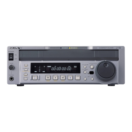
COMPACT PLAYER
J-10
J-10SDI
J-30
J-30SDI
CD-ROM
J-10/10SDI/30/30SDI
付属の
には、
(日本語、英語、フランス語、ドイツ語)が
1-6 (JP)
詳しくは
ページの「
さい。
The supplied CD-ROM includes operation manuals for J-10/10SDI/30/30SDI
Compact Player (English, Japanese, French and German versions) in PDF format.
For details, see section 1-4 "Using the CD-ROM Manual" on page 1-6 (GB).
電気製品は、安全のための注意事項を守らないと、火災
や人身事故になることがあります。
このオペレーションマニュアルには、 事故を防ぐための重要な注意事項と製
品の取り扱いかたを示してあります。 このオペレーションマニュアルをよく
お読みのうえ、 製品を安全にお使いください。 お読みになったあとは、 いつ
でも見られるところに必ず保管してください。
OPERATION MANUAL
1st Edition (Revised 7)
のオペレーションマニュアル
PDF
データ形式で入っています。
1-4 CD-ROM
マニュアルの使いかた」をご覧くだ
(J-30/30SDI)
(J-30/30SDI)
[Japanese/English]
Advertisement
Table of Contents

Related Manuals for Sony J-10


Summary of Contents for Sony J-10
- Page 1 1-4 CD-ROM 詳しくは ページの「 マニュアルの使いかた」をご覧くだ さい。 The supplied CD-ROM includes operation manuals for J-10/10SDI/30/30SDI Compact Player (English, Japanese, French and German versions) in PDF format. For details, see section 1-4 “Using the CD-ROM Manual” on page 1-6 (GB). 電気製品は、安全のための注意事項を守らないと、火災 や人身事故になることがあります。...
- Page 2 日本語 安全のために ソニー製品は安全に充分に配慮して設計されています。 しかし、 電気製品は 警告表示の意味 まちがった使い方をすると、 火災や感電などにより死亡や大けがなど人身事 このオペレーションマニュアル 故につながることがあり、危険です。 および製品では、次のような表 事故を防ぐために次のことを必ずお守りください。 示をしています。表示の内容を よく理解してから本文をお読み 安全のための注意事項を守る ください。 3 (JP)∼ 6 (JP)ページの注意事項をよくお読みください。 この表示の注意事項を守らない 定期点検を実施する と、火災や感電などにより死亡 長期間安全に使用していただくために、 定期点検を実施することをおすすめ や大けがなど人身事故につなが します。 点検の内容や費用については、 ソニーのサービス担当者または営業 ることがあります。 担当者にご相談ください。 故障したら使用を中止する この表示の注意事項を守らない と、感電やその他の事故により ソニーのサービス担当者または営業担当者にご連絡ください。 けがをしたり周辺の物品に損害 を与えたりすることがあります。 万一、異常が起きたら 1 電源を切る。 注意を促す記号...
- Page 3 2-1-1 ディスプレイ表示部 ................ 2-2 (JP) 2-1-2 サーチ操作部 ..................2-6 (JP) 2-1-3 テープ走行制御部 ................2-7 (JP) コネクターパネル ................2-8 (JP) 2-2-1 J-10/30のコネクターパネル ............2-8 (JP) 2-2-2 J-10SDI/30SDIのコネクターパネル ..........2-9 (JP) 3-1 (JP) 設置 ....................第 章 カセットの取り扱い ................3-2 (JP) 準備...
- Page 4 目次 7-1 (JP) メニューシステムの構成 ..............第 章 メニューの操作 ................. 7-2 (JP) セットアップメニュー 7-7 (JP) 基本メニュー ..................拡張メニュー .................. 7-10 (JP) 8-1 (JP) テープスラック時のカセットの取り出しかた ........第 章 8-1 (JP) 保守・点検 ヘッドクリーニング ................結露 ....................8-2 (JP) 8-3 (JP) エラーメッセージ ................8-4 (JP) デジタル時間計...
- Page 5 下記の注意を守らないと、 火災 感電 死亡 大けが や により や につながることがあります。 感電 火災 外装を外さない、改造しない 外装を外したり、改造したりすると、感電の原因となります。 内部の調整や設定および点検を行う必要がある場合は、 必ずサービストレー ニングを受けた技術者にご依頼ください。 内部に水や異物を入れない 水や異物が入ると火災や感電の原因となります。 万一、 水や異物が入ったときは、 すぐに電源を切り、 電源コードや接続コー ドを抜いて、 ソニーのサービス担当者または営業担当者にご相談ください。 電源コードを傷つけない 電源コードを傷つけると、火災や感電の原因となります。 • 電源コードを加工したり、傷つけたりしない。 • 重いものをのせたり、引っ張ったりしない。 • 熱器具に近づけたり、加熱したりしない。 • 電源コードを抜くときは、必ずプラグを持って抜く。 万一、 電源コードが傷んだら、 ソニーのサービス担当者に交換をご依頼くだ さい。 油煙、湯気、湿気、ほこりの多い場所では設置 • 使用しない...
- Page 6 下記の注意を守らないと、 けが 損害 をしたり周辺の物品に を与えることがあります。 カセット挿入口に手や指を入れない カセット挿入口に手や指を入れると、けがの原因となることがあります。 通気孔をふさがない 通気孔をふさぐと内部に熱がこもり、火災の原因となることがあります。 • 風通しの悪い、狭いところに押し込まない。 • 毛足の長いじゅうたんや布団の上に置かない。 • 布をかけない。 異常なにおい、煙が出ている状態で使用しない 異常なにおい、 煙が出ている状態で使用し続けると、 火災や感電の原因とな ることがあります。 電源を切って、 電源コードや接続を抜き、 ソニーサービ ス担当者にご連絡ください。 安全アースを接続する 安全アースを接続しないと、 感電の原因となることがあります。 次の方法で アースを接続してください。 電源コンセントが 極の場合 • 別売りの電源コードセット DK-2401(J)を使用することで安全アースが 接続されます。 電源コンセントが 極の場合 • 変換プラグ 別 売 り の 電 源 コ ー ド セ ッ ト DK-2401(J)に付属の...
- Page 7 電池についての安全上のご注意 電池の使い方を誤ると、液漏れ・発熱・破裂・発火・誤飲による大けがや失 明の原因となるので、次のことを必ず守ってください。 ここでは、 本機での使用が可能なソニー製リチウム電池についての注意事項 を記載しています。 万一、異常が起きたら • 電池の液が目に入ったら すぐきれいな水で洗い、ただちに医師の治療を受ける。 • 煙が出たら お買い上げ店またはソニーのサービス窓口に連絡する。 • 電池の液が皮膚や衣服に付いたら すぐにきれいな水で洗い流す。 • バッテリー収納部内で液が漏れたら よくふき取ってから、新しい電池を入れる。 • リチウム電池は充電しない。 • 火の中に入れない。ショートさせたり、分解、加熱しない。 • 指定された種類の電池を使用する。 • 投げつけない。 • 使用推奨期限内のリチウム電池を使用する。 • +と−の向きを正しく入れる。 • 電池を入れたまま長期間放置しない。 • 水や海水につけたり濡らしたりしない。 (JP) 電池についての安全上のご注意...
- Page 8 その他の安全上のご注意 機器を水滴のかかる場所に置かないこ と。 および水の入った物、 花瓶などを機器 の上に置かないこ と。 注意 電池を誤って交換する と爆発する危険があ り ます。 同一または同等の型のものにのみ交換してく ださい。 注意 日本国内で使用する電源コー ドセッ ト は、 電気用品安 全法で定める基準を満足した承認品が要求されます。 ソニー推奨の電源コー ドセッ ト をご使用く ださい。 警告 アースの接続は、 必ず電源プラグを電源コンセン トへ 接続する前に行ってく ださい。 アースの接続を外す場合は、必ず電源プラグを電源 コンセン トから抜いてから行ってく ださい。 警告 イ ヤホンやヘッ ドホンを使用する と きは、 音量を上げす ぎないよう...
- Page 9 章 概要 お使いになる前に 本機を初めてご使用になる場合は、使用環境に応じて、本機を NTSC (走査線数525/フ ィ ール ド周波数 60Hz) またはPAL (走査 線数 625/フィ ール ド周波数 50Hz)のいずれかに設定してく ださ い。 この設定を行わないと、本機を使用するこ とができません。 JOG/SHUTTLEボタンを押したままJOG/SHUTTLEダイヤ ルを回し、 「SEL」 の後ろに 「525」 または 「625」 を表示する。 NTSC 525/60 625/50 本機を ( ) または ( ) に設定するには SET/MENUボタ ンを押す。 タイムデータ表示部...
- Page 10 特長 高画質、高音質、高信頼性 J-10/10SDI/30/30SDI (以下 「本機」 と呼びます) は各種 イ ン チテープフォーマッ ト に基づいたコンパク ト プレーヤーです。 デジタルベータカム (J-30/30SDIのみ) 、 MPEG IMX (J-30/30SDI 本機は、従来のベータカム/ベータカムSPフォーマッ トで記録した のみ) 、 ベータカムSXの各データ レー ト に対応し、 高画質、 高音質 テープもそのまま再生する こ とができ ます。 の再生が可能です。 また、強力なエラー訂正システムを採用して います。 ご注意 • 本機はダイ ナ ミ ック ト ラ ッキング機能を搭載していないため、 テー...
- Page 11 机上に置いても場所をと らず、 使用環境に応じてフ レキシブルな設 置が可能です。 多彩な出力信号 標準で以下のイ ンターフェース を装備しているため、 広範囲の外部 機器と接続するこ とができます。 • アナログコンポジッ ト ビデオ出力 • アナログコンポーネン ト ビデオ出力(J-10/30 のみ) • Sビデオ出力 • (DV)出力 • SDI SMPTE 259M(コンポーネン トデジタルビデオ/ オーディ オ 8 チャ ンネル)出力 (J-10SDI/30SDI のみ) • アナログオーディ オ出力...
- Page 12 システム構成例 J-10/10SDI のシステム例 ベータカム カムコーダー ベータカム カムコーダー アナログカセット デジタルカセット J-10/10SDI EXT SYNC RS-232C 基準ビデオ信号発生器 コンピューター ( J-10SDI ) ( J-10SDI ) RS-422A ビ デ オ ア ナ ロ グ コ ン ポ ジット アナログコンポーネ J-10 ント ( ) ビデオモニター サーバー...
- Page 13 J-30/30SDI のシステム例 MPEG IMX カムコーダー デジタルベータカム ご注意 カムコーダー 本機は編集動作を保証していません。 ベータカム カムコーダー ベータカム カムコーダー MPEG IMX カセット デジタルベータカムカセット アナログカセット デジタルカセット J-30/30SDI RS-232C EXT SYNC 基準ビデオ信号発生器 コンピューター J-30SDI ( ) ( J-30SDI ) RS-422A ビ デ オ ア ナ ロ グ コ ン ポ ジット...
- Page 14 1-4 CD-ROM マニュアルの使いかた 付属の CD-ROMには、 Jシ リ ーズコンパク ト プレーヤーのオペレー 1-4-3 オペレーションマニュアルを読 シ ョ ンマニュアル ( 日本語、 英語、 フラ ンス語、 ドイ ツ語) が記録さ むには れています。 CD-ROMに入っているオペレーシ ョ ンマニュアルを読むには、次 のよ う にします。 1-4-1 CD-ROM の動作環境 CD-ROMをCD-ROMドライ ブに入れる。 付属のCD-ROMを動作させるには、次の環境が必要です。 • コ ンピューター : Intel Pentiumプロセッサー搭載のコンピューター 表紙ページが自動的にブラウザーで表示されます。...
- Page 15 章 各部の名称と働き コントロールパネル 1 ハンドル POWER スイッチ ディスプレイ表示部( 2-2 (JP) ページ参照) 2-6 (JP) サーチ操作部( ページ参照) 3 カセット挿入口 4 リモコン受光部 PF-1/2 ボタン PHONES ジャックとつまみ テープ走行制御部 2-7 (JP) ( ページ参照) 1 ハンドル POWER (電源)スイッチ 本機を持ち運ぶと き、 または本機を縦置きに設置する と きなどに使 ON側を押すと電源が入り、 ディ スプレイ 表示部のFL管表示とイ ン 用します。...
- Page 16 コントロールパネル 3 カセット挿入口 工場出荷時には、 「テープリ メイ ンタイ ム」 が割り付けられていて、 Sカセッ ト 、 Lカセッ ト を入れます。 PF-2ボタ ンを押している間、 ディ スプレイ 表示部にテープ残量が表 示されます。 4 リモコン受光部 付属のリモー ト コマンダーからの赤外線を受光します。 ◆ 機能の割り付けかたについて詳しく は、 「メニューバンクの操作 (基本 メニュー項目 B01 ∼B12) 」 (7-5 (JP)ページ) をご覧く ださい。 ◆ リ モー ト コマンダーについて詳しく は、 「 4-3 リ モー ト コマンダーを使った再 生操作」...
- Page 17 SET/MENU MPEG IMX J-30/30SDI (セット メニュー) ボタン フォーマット使用時( ) セッ ト アップメニューの操作と設定に使用します。 出力モード STEREO MONO SHIFTボタ ンを押したままSET/MENUボタ ンを押すと、 セッ ト アッ オーディオチャンネル プメニューの内容がディ スプレイ 表示部に表示されます。 設定が終 1 回押し CH-1 CH-2 CH-1 CH-1 わったらSET/MENUボタ ンだけを押します。 設定した内容が確定 2 回押し CH-3 CH-4 CH-2 CH-2 され元の状態に戻り...
- Page 18 コントロールパネル CTL/TC/UB DOLBY C NRボタ ンと して使用するには、 SHIFTボタ ンを押したま (表示切り換え)ボタン ま このボタ ンを押します。 ディ スプレイ 表示部にDOLBY C NRイ ンジ ディ スプレイ 表示部のタイ ムデータをCTL、 TC、 UBの順に切り換え ケーターが点灯します。 ます。表示を切り換えると、ディ スプレイ表示部の上のイ ンジケー オキサイ ドテープ使用時、 アナログオーディ オに対する ドルビーNR ターも対応して点灯 / 消灯します。 (ノ イ ズリ ダク シ ョ ン)Cタ イ プの雑音低減システムをオン/オフ します。 タイムデータ表示の選択と表示の内容...
- Page 19 オーディオモニター表示部 タイムデータ表示部 インジケーター部 ※ テープ走行インジケーター部 オーディオモニター表示部 タイ ムコー ド表示 イ ンジケーター: タイ ムデータ表示部にタイ • • L/R オーディ オレベルメーター:任意の L/R (左 / 右) 2 チャン ムコー ドが表示される と点灯します。 ネルのオーディ オレベルを表示します。 ユーザービッ ト表示 イ ンジケーター:タイ ムデータ表示部に • • L/R オーディ オチャ ンネル表示:任意の選択したチャ ンネル番 ユーザービッ...
- Page 20 コントロールパネル SHUTTLE テープ走行インジケーター部 (シャトル)ダイヤル • テープ走行イ ンジケーター 下表に示すモー ドの再生を行う と き回します。 右に回すと正方向再 テープ走行制御部のボタ ンを押すと、 そのボタ ンに対応するイ ン 生、左に回すと逆方向再生を行います。 ジケーターが点灯します。 m:REWイ ンジケーター JOG/SHUTTLEボタ ンを押して JOGダイ ヤルを回すとジ ョ グモー B:PLAYイ ンジケーター ドに、 SHUTTLEダイ ヤルを回すとシャ トルモー ドに切り換わり ます。 AUTO TRACKING 引き込み動作中には点滅します。 JOG/SHUTTLE ダイヤルによる再生のモード M:F FWDイ...
- Page 21 F FWD (早送り) ボタン 2-1-3 テープ走行制御部 テープを早送り したいと き押し、 ディ スプレイ 表示部のF FWDイ ン ジケーターを点灯させます。 また、 シ ョ ッ トマークが記録されている テープを使用している と きは、 SHIFTボタ ンを押したまま このボタ ン EJECT ボタン を押すこ とによ り 、 現在のテープ位置よ り フ ォ ワー ド方向にある シ ョ ッ ト...
- Page 22 コネクターパネル コネクターパネル 2-2-1 J-10/30 のコネクターパネル AC IN 端子 RS232C 端子 REMOTE IN (9P) 端子 VIDEO EXT SYNC 入力端子 AUDIO MONITOR OUTPUT 端子 OUTPUT 端子 VIDEO OUTPUT (ビデオ出力)端子 AC IN ( 電源入力) 端子 COMPOSITE SUPER) (アナログコンポジッ ト ビデオ) ( 出 電源コー ド (別売り) を使って電源コ ンセン ト に接続します。...
- Page 23 ご注意 • 6 ピン型のDV 端子を持つ機器と本機を接続する場合は、 相手側機器の6ピン型の DV 端子から先に接続してく だ • 本機の DV 端子に接続できる機器は、通常 1 台だけで さい。 す。 複数台を接続できるDV対応機器と接続する ときは、 接続する機器の取扱説明書をご覧く ださい。 COMPONENT (コンポーネン ト) ( − − ) 出力端子 • 本機のi.LINK (DV) 出力は、 ノ ン リニア編集用ソフ ト をイ ( 型) :アナログコンポーネン ト ビデオ信号(Y/R − Y/ ンス...
- Page 24 コネクターパネル REMOTE IN (リモート入力) ( ) 端子 ( ピン、 • 6ピン型の DV 端子を持つ機器と本機をDV ケーブルで 422A シリアルインターフェース) 接続する場合、 DV ケーブルを抜き差しする と きは、 あ らか ソニー9ピン リ モー ト機能を備えた外部機器から本機を遠隔操作す じめ機器の電源を切って電源プラグをコ ンセン ト から抜い る場合に使用します。 てく ださい。 機器の電源プラグを差したままDVケーブル を抜き差しする と、 機器のDV 端子から出力している高電 EXT SYNC (外部同期)入力端子...
- Page 25 章 準備 設置 本機は、横置きでも縦置きでも使用するこ とができます。ただし、 縦置きに設置する場合は、 必ず付属の縦置き用スタ ン ドを使用し、 図のよ う に固定してく ださい。 ご注意 • 本機を縦置きでご使用になる場合は、 必ずハン ドルが上になるよ う に設置してく ださい。 • 横置き、 縦置きのいずれの場合でも、 本機の周囲は5 cm以上あ 縦置き用スタンド けてく ださい。 第 章 準備 (JP)
- Page 26 カセットの取り扱い 設置 テープのたるみを取るには 再生可能なカセット 指で一方のリ ールを押し込みながら、 リ ールが回らなく なるまで矢印 本機では、 以下のテープ幅 イ ンチのカセ ッ トの再生が可能です。 の方向へ軽く 回します。 • デジタルベータカムカセッ ト (J-30/30SDI のみ) • MPEG IMXカセッ ト (J-30/30SDI のみ) • ベータカムSXカセッ ト • ベータカムSPカセッ ト • ベータカムカセッ ト • UVW 用カセッ ト カセットを出し入れするには...
- Page 27 章 再生 再生操作 テープが終わりまで再生されると 4-1-1 通常再生 自動的にテープの初めまで巻き戻されて止ま り ます。 (拡張メニュー項目 125 のAUTO REWINDが ENA の場合) SHIFT ボタン カセット挿入口 ご注意 • ベータカムSXテープまたはデジタルベータカムテープを再生した 直後にベータカムテープまたはベータカムSPテープを再生する と、再生の開始に時間がかかる ことがあ り ます。 • 本機はオー ト ト ラ ッキングを採用しています (デジタルベータカム、 MPEG IMX使用時) 。 工場出荷時の設定はAUTO TRACKING ONに設定されていますが、 OFFに設定を変える こ と もできます。 設定変更のしかたについて詳しく...
- Page 28 再生操作 4-1-2 4-1-3 ジョグモードの再生 シャトルモードの再生 1,2,3 1,2,3 ジ ョ グモー ドの再生では、 JOGダイ ヤルの回転速度によ り再生速度 シャ トルモー ドの再生では、 SHUTTLEダイ ヤルの回転角度によ り を変化させるこ とができ ます。再生速度の可変範囲は±1 倍速で 再生速度を段階的に変化させる こ とができます。 す。 • デジタルベータカムテープ使用時:±21 倍速 ジ ョ グモー ドで再生を行う には、以下のよう に操作します。 • MPEG IMXテープ使用時: ±32倍速/±38倍速 (NTSC/PAL) •...
- Page 29 SHUTTLEダイ ヤルを、 希望の再生速度になる角度だけ希望 ノイズレスモードを設定するには の方向に回す。 セッ トアップメニューの基本メニュー項目 025 の NOISELESS で Enableを選択します。 (出荷時は Disableに設定されています。 ) シャ トルモー ド再生が始ま り ます。 ディ スプレイ 表示部の JOGまたは SHTL 表示が点滅します。 シャ トルモー ド再生を止めるには、 SHUTTLEダイ ヤルをセン ターのク リ ックする位置に戻すか、 STOPボタ ンを押す。 ノイズレス再生を実行するには 本機をノ イ ズレスモー ドに設定し、 JOG/SHUTTLEボタ ンを押して なお、拡張メニュー項目...
- Page 30 再生操作 ご注意 4-1-5 繰り返し再生 (リピート再生) 機 能 • 開始点と して記憶されるタイ ムコー ドは LTC のみです。 VITC や CTLを使用して開始点を設定する こ とはでき ません。 繰り返し再生 (リ ピー ト再生) 機能を使用する と、 指定した区間を繰 • すでに終了点が設定されている場合に、終了点よ り後ろに開始 点を設定する (終了点よ り大きいタイ ムコー ド値を開始点にする) り返し再生させる こ とができます。 と、設定済み終了点が削除されます。 リピート再生モードを設定するには テープの初め...
- Page 31 テープの初め 終了点 開始点 テープの終わり 開始点より前に終了点を設定すると テープの初め 終了点 テープの終わり 開始点が削除される リピート再生を実行するには PLAYボタ ンを押します。 設定済み開始点・終了点のタイムコードを確認す るには STOPボタ ンとPLAYボタ ンを同時に押したままにします。 押してい る間、 タイ ムデータ表示部に 「START」 → 「開始点タイ ムコー ド」 → 「END」→「終了点タイ ムコー ド」→「STRAT」の順に繰り返し表 示されます。 設定済み開始点・終了点を削除するには EJECTボタ ンを押してカセッ ト を排出します。 開始点および終了点 の両方が削除されます。 第 章 再生 (JP)
- Page 32 スーパーインポーズされる文字情報 スーパーインポーズされる文字情報 表示内容 1 タイムデータの種類 1 タイムデータの種類 タイムデータ 表示 意味 2 タイムデータのドロップ CTLカウンターのデータ フレームマーク LTCリ ーダーのタイ ムコー ドデータ VITC データの LTCリ ーダーのユーザービッ トデータ フィールドマーク TCR. VITCリ ーダーのタイ ムコー ドデータ UBR. VITCリ ーダーのユーザービッ トデータ ご注意 タイ ムデータやユーザービッ ト を正しく 読みとれなかったと きは、 4 動作モード...
- Page 33 表示 動作モード ブロック ブロック TAPE UNTHREAD カセッ ト が装着されていない STANDBY OFF ス タ ンバイ オフモー ド STOP ス ト ップモー ド F.FWD 早送りモー ド 巻き戻しモー ド PLAY 再生モー ド (サーボアンロ ッ ク) PLAY LOCK 再生モー ド (サーボロ ック) STILL ジ ョ グモー ドの静止画 正方向のジ...
- Page 34 リモートコマンダーを使った再生操作 リモートコマンダーを使った再生操作 リ モー ト コマンダーを使用する前に、 電池部の透明フ ィ ルムを引き抜 リモートコマンダーのご注意 いてく ださい。 • リモー ト コマンダーと本体のリモコン受光部の間に障害物がある と、 操作できないこ とがあり ますので、 本体の前面にある リモコン 受光部に向けてリモー ト コマンダーを操作してく ださい。 4-3-1 電池を交換するには • リ モー ト コマンダーで操作でき る範囲は限られています。 本体に近 く 、 リモコン受光部に対して直角なほど操作が可能になり ます。 リチウム電池入れを引き出す。 4-3-2 つまんでロ...
- Page 35 REMOTE INTERFACE ❉ 213:WIRELESS-on リモートコマンダー ❉ 印以外の項目表示は省略しています。 ご注意 (JOG/SHUTTLEボタ ンを押している間は ONが点滅して表 複数台のJ-10/10SDI/30/30SDIまたはJ-H1/H3 (J-Hシリ ーズ) を 示されます。 ) 並べてリ モー ト コマンダーを操作する と、 複数台同時に動作する こ とがあ り ます。 SET/MENUボタ ンを押す。 その場合は、動作させたく ないセッ トの拡張メニュー項目 213 の WIRELESS REMOTE CONTROLをOFFに設定してく ださい。 タイ ムデータ表示部はメニュー設定表示から抜け、 通常の表示...
- Page 37 章 UMID 機能 5-1 UMID 機能の概要 UMID (Unique Material Identifier) とは、 SMPTE 330Mに規定 BasicのみのUMIDを 「Basic UMID」 、 BasicにSource Packを加 されている映像 ・ 音声素材のメ タデータです。 本機では、 デジタル えたUMIDを 「Extended UMID」 と呼びます。下図は、 UMIDに ベータカムおよび MPEG IMXフォーマッ トで記録された UMIDを 含まれる情報を表す概念図です。 再生する ことができ ます。 UMIDは 「Basic」 と呼ばれる情報と、 「Source Pack」 と呼ばれる 情報があり...
- Page 38 5-2 UMID の出力と表示 こ こでは、 UMID の出力と表示について説明します。 UMID モニター画面での 表示 デジタルベータカムフォーマッ ト (J-30SDI)および MPEG IMX 5-2-1 UMID の出力に関する設定 フォーマッ ト (J-30/30SDI) での再生時には、 コネク ターパネルの COMPOSITE ( SUPER)出 力 端 子、 SDI ( SUPER)出 力 端 子 UMIDを SDI 信号に出力するか否か、出力する場合は Basic (J-30SDI のみ)...
- Page 39 章 エッセンスマーク エッセンスマーク機能の概要 エッセンスマーク( Essence Mark)とは、SMPTE RP210A Metadata Dictionaryで規定されているディ クシ ョ ナリ ーアイ テムの Term Valueを使い、 記録開始点や編集点の候補となるポイ ン ト を 最大 32 バイ トのデータで表現 / 伝送する機能です。 SMPTE RP210A Metadata Dictionary の基 本 記 述 形 式は、 SMPTE 336M Data Encoding Protocol using Key-Length-Value (KLVコーディ...
- Page 40 エッセンスマークの出力 テープ再生時、 テープに記録されているエッセンスマークをSDI信 号に出力する こ とができます。 また、 テープに記録されているシ ョ ッ ト マークなどの情報をエッセンスマークに変換して出力する こ とがで きます。 エッセンスマークを出力するか否かの選択 再生時にテープに記録されているエッ センスマーク を出力するか否 かを選択する こ とができ ます。 この選択は、 拡張メニュー項目657 のESSENCE MARK TAPE OUTPUTを使用して行います。 ◆ 拡張メニュー項目 657については、 7-11 (JP)ページをご覧く ださい。 ショットマークをエッセンスマークに変換して出 力する 再生時にテープに記録されているシ ョ ッ ト マーク をエッセンスマーク に変換して出力するか否かを選択する...
- Page 41 章 セットアップメニュー メニューシステムの構成 本機では、 操作前の主要なセッ ト アップはメニューを操作して行え 本機では、 2種類までのメニュー設定をメニューバンク1、 2に保存 るよ う になっています。 しておく こ とができます。 保存したメニュー設定は、 必要時に呼び 出して使用する こ とができます。 本機では以下のセッ ト アップメニューを使用します。 ◆ 詳しく は、 「メニューバンクの操作 (基本メニュー項目B01∼B12) 」 (7- • 基本メニュー 5 (JP)ページ) をご覧く ださい。 デジタル時間計に関する表示、文字情報の内容や表示、 525 (NTSC) /625 (PAL) システムの切り換えなどに関する設定、 さ らにメニューの設定を保存するメニューバンクに関する設定など...
- Page 42 メニューの操作 メニューの操作 こ こでは基本メニューの設定表示と設定変更について説明します。 カーソル (現在選択さ *HO1:OPE HOURS ◆ 基本メニュー項目013とB01∼B12の操作については、 「525/625システ HO2:DRUM HOURS れてる項目を示す) ムの切り換え (基本メニュー項目013) 」 (7-4 (JP)ページ) と 「メニューバ ンクの操作 (基本メニュー項目B01∼B12) 」 (7-5 (JP)ページ) をそれぞ れご覧く ださい。 ◆ 拡張メニューの操作については、 「 拡張メニューの操作」 ( 7-6 (JP)ペー ジ) をご覧く ださい。 メニューの設定を表示させるには SHIFTボタ...
- Page 43 メニュー項目の設定値を変更するには メニューを工場出荷値の設定に戻すには (基本メニュー項目 ) 表示中のメニュー項目の設定値を変更するには、 以下のよ う に操 作します。 タイムデータ表示部 SET/MENU ボタン JOG/SHUTTLEボタ ンを押したまま、 JOG/SHUTTLEダイ ヤ ルを回す。 基本メニュー項目 B20 のRESET SETUPをONに設定する。 SHUTTLEダイ ヤルの回転角度またはJOGダイ ヤルの回転速 タイ ムデータ表示部に「PUSH SET」 、モニター画面には 度に応じた速さで設定値が変わり ます。 「Push SET button」 と表示されます。 SET/MENUボタ ンを押す。 カ レン ト メニュー ( 「メニューバンクの操作 (基本メニュー項目 B01∼B12)...
- Page 44 メニューの操作 JOG/SHUTTLEボタ ンを押したまま、 JOG/SHUTTLEダイ ヤ 525/625 システムの切り換え 基本メニュー項目 013) ルを回して設定をOFF からONに切り換える。 以下の手順により、基本メニュー項目 013 の 525/625 SYSTEM 表示が以下のよう に変わり ます。 SELECTをONにして 525 (NTSC)システムと625 (PAL)システム の切り換えを行う こ とができます。 タイムデータ表示部 (以下の操作手順は、 525 (NTSC)システムから625 (PAL)システム に切り換える場合の例です。 ) モニター ITEM-013 基本メニュー項目 013を選択して表示させる。 525/625 SYSTEM SELECT タイ...
- Page 45 メニューバンクの操作 (基本メニュー項目 ∼ JOG/SHUTTLEボタ ンを押したまま、 JOG/SHUTTLEダイ ヤ ) ルを回して設定を525から625に切り換える。 表示が以下のよ う に変わり ます。 本機では、 2種類までのメニュー設定をメニューバンク1、 2に保存 しておく こ とができます。 保存したメニュー設定は、 必要時に呼び タイムデータ表示部 出して使用するこ とができます。 メニューバンク操作項目にジャンプするには SHIFTボタ ンを押したままSET/MENUボタ ンを押してからJOG/ モニター SHUTTLEダイ ヤルを回して必要な項目を選択する こ とができ ます。 525/625 SYSTEM SELECT SHIFTボタ ンを押したままSET/MENUボタ ンを押してからCTL/ TC/UBボタ...
- Page 46 メニューの操作 拡張メニューの操作 拡張メニューも、基本メニューと同じ手順で操作でき ます。 ◆ 基本メニューの操作については、 7-2 (JP)ページをご覧く ださい。 ご注意 拡張メニューを開く には、 基本メニュー項目099のMENU GRADE をENHANに設定する必要があ り ます。 (JP) 第 章 セットアップメニュー...
- Page 47 基本メニュー 基本メニューには以下の項目があ り ます。 表の設定の欄で、工場出荷時の設定は□で囲んで示してあ り ます。 項目番号 項目名 設定 CHARACTER H-POSITION COMPOSITE (SUPER) 出力端子、 SDI (SUPER)出力端子(J-10SDI/30SDI)、 DV 端子から出 力される タイ ムコー ドなどの文字情報の水平位置を設定する。 ∼ ∼ :00にする と画面左端から表示され、数字が増える と1 文字分ずつ右へ移動す る。 a),b) CHARACTER V-POSITION COMPOSITE (SUPER) 出力端子、 SDI (SUPER)出力端子(J-10SDI/30SDI)、 DV 端子から出 力される...
- Page 48 基本メニュー 項目番号 項目名 設定 CONDITION DISPLAY ON VIDEO スーパーイ ンポーズ中の文字に、チャ ンネル状態を追加表示するかど うかを設定する。 disable MONITOR :表示を行わない enable (CHARACTER V-SIZEが×1 の設定 :表示を行う 時のみ表示可能) 表示方法 文字上のタイ マーまたはステータス表示行の下に表示されます。 (ただしアナログテープ挿入時 は、 ビデオの再生レベルのみ表示されます。 ) (例) — — “V” に続く 文字は、回転ヘッ ドのビデオチャ ンネルの状態を表示します。 “A” に続く 文字は、回転ヘッ ドのオーディ オチャ ンネルの状態を表示します。 文字パターン...
- Page 49 項目番号 項目名 設定 SDI (SUPER)出力端子から出力される映像信号に文字情報をスーパーイ ンポーズ (重ねて表 SDI OUT CHARACTER 示)するかどうかを設定する。 (J-10SDI/30SDI のみ) :スーパーイ ンポーズしない。 :スーパーイ ンポーズする。 i.LINK CHARACTER DV 端子から出力される映像信号に文字情報をスーパーイ ンポーズ(重ねて表示) するかどうか を設定する。 :スーパーイ ンポーズしない。 :スーパーイ ンポーズする。 設定 項目番号 項目名 MENU GRADE 設定変更可能なメニューを指定する。 BASIC :基本メニュー ENHAN :基本メニュー+拡張メニュー RECALL BANK 1 メニューバンク1をカ...
- Page 50 拡張メニュー 拡張メニュー 拡張メニューには以下の項目があ り ます。 表の設定の欄で、工場出荷時の設定は□で囲んで示してあ り ます。 項目番号 項目名 設定 SELECTION FOR JOG/SHUTTLE 本機をジ ョ グ /シャ トルモー ドにする方法を設定する。 DIAL ENABLE DIAL : JOG/SHUTTLEダイ ヤルを回すとジ ョ グ /シャ トルモー ドに入る。 : JOG/SHUTTLEボタ ンを押すとジ ョ グ /シャ トルモー ドに入る。 MAXIMUM TAPE SPEED 早送り、巻き戻し、...
- Page 51 項目番号 項目名 設定 デジタルベータカムまたは MPEG IMXフ ォーマッ ト使用時に、テープに記録されているUMID UMID OUTPUT (J-30SDI のみ) データ をSDI 出力端子から出力するかどうか、 また出力する場合はどのよ う に出力するかを選択 する。 :テープに記録されているUMID データ を出力しない。 BASIC :テープに記録されているUMID データのう ちBasic UMID のデータ (32byte) を出力す る。 EXTENDED :テープに記録されているUMID データ をExtended UMID のデータ (64byte) と して出力する。 ご注意...
- Page 52 拡張メニュー 項目番号 項目名 設定 CHROMA GAIN CONTROL クロマ出力レベルを調節する。 初期設定値: CHROMA PHASE CONTROL クロマ位相を調節する。 コンポジッ ト信号のみ可変できます。 初期設定値: SETUP LEVEL(525ライ ンモー ド) / セッ ト アップレベル(ブラ ッ ク レベル) を調節する。 BLACK LEVEL(625ライ ンモー ド) 初期設定値: SYSTEM PHASE SYNC 出力信号のシンク位相を調節する。 初期設定値: Y/C DELAY アナログベータカムカセッ...
- Page 53 章 保守・点検 テープスラック時のカセットの取り出しかた 本機内部でテープス ラ ッ クが発生した場合は、 天板と底板を取り外 して作業する必要があ り ます。 この作業は必ずサービス ト レーニン グを受けた技術者が行ってく ださい。 ◆ 詳しく はメ ンテナンスマニュアルをご覧く ださい。 ヘッドクリーニング ビデオヘッ ドやオーディ オヘッ ドをク リ ーニングする と きは、 必ず専 用のク リ ーニングカセッ ト テープ BCT-HD12CLをお使いく ださい。 使用方法を誤る とヘッ ドを傷める こ とがあ り ますので、 ク リ ーニング カセッ...
- Page 54 結露 テープスラック時のカセットの取り出しかた 寒い場所から暖かい場所に本機を移動させたり 、 冬に暖房を入れ ALARM 電源を入れた直後に インジケーターと た直後の部屋や温度の高い部屋に本機を置く と、 VTR内部のヘッ 「 E10-0000 」表示が点灯したときは ド ドラムやテープガイ ドに水滴が生じる こ とがあ り ます。 これを結露 電源を入れたまま、 ALARMイ ンジケーターとエラー表示が消えるま といいます。 でお待ち く ださい。 点灯している間はカセッ ト を入れる こ とはできま 結露の状態のと きにテープを走行させる と、水滴のついている部 せん。 分にテープが貼り付き、 テープを傷めてしま う恐れがあ り ます。 これ ALARMイ...
- Page 55 エラーメッセージ コード メッセージ 内容 REEL TROUBLE ス レッディ ング、 またはアンス レッディ ング時に、 「テープたるみ」 を検出 REEL TROUBLE サーチ、早送り、 または巻き戻し時に、 「テープたるみ」 または「テープ切れ」 を検出 REEL TROUBLE 再生時に、 「テープたるみ」 、 「テープ切れ」 、 あるいは 「S 側リ ール、 またはT 側リ ールのロ ッ ク」 を検出 REEL TROUBLE 早送り、...
- Page 56 デジタル時間計 テープスラック時のカセットの取り出しかた デジタル時間計には9種類の表示モー ドがあ り 、 それぞれのモー ド H14: THREADING (スレッディング回数表示)モード(リ ごとに、 本機の動作の経過時間または回数を累積してタイ ムデータ セット可能) 表示部に表示します。 この時間計を目安と して、定期点検を行っ H04モー ドと同様の機能です。 リ セッ ト が可能です。 ス レッディ ング てく ださい。 モーターなどの交換時間の目安になり ます。 H16: REEL SHIFT (リールシフト回数表示)モード(リ デジタル時間計の表示モードについて セット可能) H06 モー ドと同様の機能です。 リ セッ ト が可能です。 デジタル時間計には以下の...
- Page 57 5℃∼ 40℃ PAL: 220 分 (BCT-184MXL使用時) 保存温度 −20℃∼+ 60℃ ベータカムSX 194 分(BCT-194SXLA 使用時) 湿度 25% ∼ 80% アナログベータカム 質量 J-10/10SDI:8.1kg NTSC:90 分(BCT-90MLA 使用時) J-30/30SDI:8.2kg PAL:108 分(BCT-90MLA 使用時) 外形寸法 307×100×397mm(幅 / 高さ/ 奥行き) 早送り ・巻き戻し時間 約 5 分 (BCT-194SXLA 使用時) サーチ速度 テープ走行系...
- Page 58 仕様 再生可能テープ デジタルベータカムカセッ ト (J-30/30SDI) ベータカムSXフ ォーマッ ト使用時(J-10/30) MPEG IMXカセッ ト (J-30/30SDI) Y:0.5∼ 4.5MHz + 0.5dB/−4.5dB ベータカムSXカセッ ト (NTSC) ベータカムSPカセッ ト Y:0.5∼ 5.5MHz + 0.5dB/−4.5dB ベータカムカセッ ト (PAL) UVW 用カセ ッ ト R− Y/B−Y:0.5∼ 2.0MHz + 0.5dB/ −4.5dB 56dB 以上...
- Page 59 S VIDEO Mini DIN 4ピン (1) 、 Y:1.0 Vp-p、 C: リモート端子 0.286 Vp-p バース ト 、 75 Ω RS232C D-sub 9ピン、オス、 ソニー9ピン リモー ト イ ンターフェース IEEE1394(1) 、 6ピン REMOTE IN (9P) D-sub 9ピン、メス、 ソニー9ピン PHONES JM-60ステレオフォーンジャ ック リモー ト イ ンターフェース −∞∼−12dBu (8 Ω負荷時)...
-
Page 60: Important Safety Instructions
English Important Safety Instructions THIS APPARATUS MUST BE EARTHED. • Read these instructions. • Keep these instructions. • Heed all warnings. • Follow all instructions. • Do not use this apparatus near water. • Clean only with dry cloth. • Do not block any ventilation openings. Install in accordance with the manufacturer’s instructions. - Page 61 (entretien/réparation) importantes Electromagnetic Environments: dans la documentation accompagnant E1 (residential), E2 (commercial and light industrial), E3 l’appareil. (urban outdoors), E4 (controlled EMC environment, ex. TV studio). The manufacturer of this product is Sony Corporation, 1-7-1 Konan, Minato-ku, Tokyo, Japan.
- Page 62 Gehörschäden verursachen. Um dieses Produkt sicher zu verwenden, vermeiden Sie längeres Hören bei sehr hohen Le fabricant de ce produit est Sony Corporation, 1-7-1 Schalldruckpegeln. Konan, Minato-ku, Tokyo, Japon. Le représentant autorisé pour EMC et la sécurité des produits est Sony Deutschland GmbH, Hedelfinger Strasse 61, 70327 Stuttgart, Allemagne.
- Page 63 E1 (Wohnbereich), E2 (kommerzieller und in beschränktem Maße industrieller Bereich), E3 (Stadtbereich im Freien) und E4 (kontrollierter EMV-Bereich, z.B. Fernsehstudio). Der Hersteller dieses Produkts ist Sony Corporation, 1-7-1 Konan, Minato-ku, Tokyo, Japan. Der autorisierte Repräsentant für EMV und Produktsicherheit ist Sony Deutschland GmbH, Hedelfinger Strasse 61, 70327 Stuttgart, Deutschland.
-
Page 65: Table Of Contents
Parts 2-1-3 Tape Transport Control Section ........2-7 (GB) 2-2 Connector Panel ..............2-8 (GB) 2-2-1 Connector Panel of the J-10/30 ........2-8 (GB) 2-2-2 Connector Panel of the J-10SDI/30SDI ...... 2-10 (GB) 3-1 Installation ................3-1 (GB) Chapter 3 3-2 Cassettes ................. - Page 66 Table of Contents 8-1 Removing a Cassette When Tape Slack Occurs ....8-1 (GB) Chapter 8 8-2 Head Cleaning ............... 8-1 (GB) Maintenance and 8-3 Moisture Condensation ............8-2 (GB) Inspection 8-4 Error Messages ..............8-3 (GB) 8-5 Digital Hours Meter .............. 8-4 (GB) Specifications ................
-
Page 67: Before Using
Chapter Overview 1-1 Before Using When using this unit for the first time, set the number of scan lines to the NTSC (525 scan lines, field frequency 60 Hz) system setting or to the PAL (625 scan lines, field frequency 50 Hz) system setting Holding down the JOG/SHUTTLE button, turn the according to the operating environment in which the JOG/SHUTTLE dial to display “525”... -
Page 68: Features
1-2 Features The J-10/10SDI/30/30SDI (also referred to simply as Playback compatibility with Betacam/ the unit(s) in this manual) are compact players based Betacam SP on the -inch tape format. They play tapes recorded in conventional Betacam/ The unit plays tapes recorded in the Betacam/Betacam Betacam SP format. - Page 69 This unit can output digital video/audio signals in DV format compatible with i.LINK from the DV output connector........................................... is a trademark of Sony Corporation and indicates that this product is in agreement with IEEE 1394-1995 specifications and their revisions. Chapter 1 Overview (GB)
-
Page 70: Sample System Configuration
1-3 Sample System Configuration Example for the J-10/10SDI Betacam SX camcorder Betacam SP camcorder Analog cassette Digital cassette J-10/10SDI EXT SYNC RS-232C Reference video signal generator Computer SDI (J-10SDI) SDI (J-10SDI) RS-422A S video/analog composite/ analog component (J-10) Video monitor... - Page 71 Example for the J-30/30SDI MPEG IMX camcorder Digital Betacam camcorder Betacam SX camcorder Betacam SP camcorder Digital Betacam MPEG IMX cassette cassette Analog cassette Digital cassette J-30/30SDI EXT SYNC RS-232C Reference video signal generator Computer SDI (J-30SDI) SDI (J-30SDI) RS-422A S video/analog composite/ analog component (J-30) Video monitor...
-
Page 72: Using The Cd-Rom Manual
You can purchase a new CD-ROM disc to replace one that has been lost or damaged. Contact your Sony 1-4-2 Preparations service representative. -
Page 73: Control Panel
Chapter Location and Function of Parts 2-1 Control Panel 1 Carrying handle 2 POWER switch Display section Search control section (See page 2-2 (GB)) (See page 2-6 (GB)) 3 Cassette compartment 4 Remote control detector 6 PHONES jack and 5 PF-1/2 buttons Tape transport control control knob section (See page 2-7 (GB)) -
Page 74: Display Section
2-1 Control Panel 3 Cassette compartment Function “tape remain time” is assigned to the PF-2 button as the factory default settings. While you are Insert an S or L cassette. pressing the button, the remaining tape time are 4 Remote control detector displayed in the display section. - Page 75 2 SET/MENU button For the MPEG IMX format (J-30/30SDI) Use this button for setup menu operations and settings. Output mode STEREO MONO Press the SET/MENU button while holding down the Audio channel SHIFT button to display the contents of the setup Press once CH-1 CH-2...
- Page 76 2-1 Control Panel Press this button while holding down the SHIFT 5 CTL/TC/UB (display switching) button This selects the time data displayed in the fluorescent button to function the DOLBY C NR button. The display in the following sequence: CTL, TC, UB. As DOLBY C NR indicator lights in the display section.
- Page 77 Audio monitor display area Time data display area Indicator area ❉ Tape transport indicator area Audio monitor display area • UB (user bits) indicator: This lights when a user bit • L/R audio level meter value is displayed in the time data display area. Indicates the audio levels of the 2 optionally selected •...
-
Page 78: Search Control Section
2-1 Control Panel Tape transport indicator area 3 SHUTTLE dial • Tape transport indicator Turn this to carry out playback in the modes shown in When you press each button in the tape transport the following table. Turn the dial clockwise for control section, the corresponding indicators light. -
Page 79: Tape Transport Control Section
• If the unit carries out reverse playback in the shuttle 4 F FWD (fast forward) button mode at –0.5 times or less normal speed for 20 To start fast forwarding the tape, press this button. The consecutive minutes, the reel motor heat protection F FWD indicator in the display section lights. -
Page 80: Connector Panel
OFF, the output from this connector outputs superimposed Used to remote-control this unit from an external device provided with a Sony 9-pin remote control character information such as time code, menu interface. - Page 81 • The i.LINK (DV) output of this unit is used to provide materials to a computer on which non- linear editing software is installed. You can use a Sony VTR equiped with an i.LINK (DV) connector (DVCAM series of VTRs for example) with this unit, though, the auto dubbing function and editing function will not be available.
-
Page 82: Connector Panel Of The J-10Sdi/30Sdi
OFF, the output from this connector outputs Used to remote-control this unit from an external device provided with a Sony 9-pin remote control superimposed character information such as time interface. - Page 83 • The i.LINK (DV) output of this unit is used to provide materials to a computer on which non- linear editing software is installed. You can use a Sony VTR equiped with an i.LINK (DV) connector (DVCAM series of VTRs for example) with this unit, though, the auto dubbing function and editing function will not be available.
-
Page 85: Installation
Chapter Preparations 3-1 Installation You can install this unit horizontally as well as vertically. However, it is necessary to use the supplied vertical installation stands to prepare the unit for vertical installation as shown in the figure. Notes • When you install this unit vertically, be sure that the handle faces up. -
Page 86: Cassettes
3-2 Cassettes Removing slack from the tape Cassette types Press one of the reels in with a finger, and turn gently in the direction shown by the arrows until there is no This unit uses the following -inch tape width slack in the tape. -
Page 87: Playback Procedures
For details on how to change the setting, contact your DOLBY C NR button STOP button nearest Sony dealer. While this unit is pulling the tape in, the PLAY button indicator B flashes. PLAY button When using the Dolby C NR system Insert a cassette beforehand. -
Page 88: Playback In Jog Mode
4-1 Playback Procedures 4-1-2 Playback in Jog Mode 4-1-3 Playback in Shuttle Mode 1,2,3 1,2,3 In jog mode, the JOG dial controls the playback speed In shuttle mode, the SHUTTLE dial controls the based the speed at which the dial is turned. The playback speed based on the angular position of the dial. -
Page 89: Function
Turn the SHUTTLE dial to the angle 4-1-4 Noiseless Playback corresponding to the desired playback speed. Function and Frame Step Playback Function Playback in shuttle mode starts. When you are using the Betacam SX or MPEG IMX Return the SHUTTLE dial to the center indent position or press the STOP button to cancel shuttle format, you can put this unit into noiseless mode for noiseless jog and shuttle playback at up to ±0.5 times... -
Page 90: Repeat Playback Function
4-1 Playback Procedures To perform frame step playback To set the start point and end point of repeat playback Put the unit into noiseless mode and press the PF-1 or PF-2 button. When a cassette is loaded in the unit, you can specify When you are using the Betacam SX format, each the current tape position as the start or end point of press of the PF-1 button steps 2 frames back, and each... - Page 91 To set the end point To check the time code of the set start Holding down the STOP button, press the F FWD point and end point button. The time code (LTC) value of the tape position when the F FWD button was pressed is stored in Hold down the STOP button and PLAY button memory as the end point time data.
-
Page 92: Superimposed Character Information
4-2 Superimposed Character Information 4-1 Playback Procedures Displayed items 1 Types of time data 1 Types of time data Time data Display Meaning 2 Drop frame mark CTL counter data of time data LTC reader time code 3 VITC field mark LTC reader user bit TCR. -
Page 93: Using The Remote Commander
4-3 Using the Remote Commander Pull off the transparent film covering the battery parts. 4-3-2 Setting Menu When a Remote Commander is used, WIRELESS 4-3-1 How to Change the REMOTE CONTROL, extended menu item 213, must Lithium Battery to be set to ON. (It is set to OFF at the factory.) (The following operation is an example of how WIRELESS REMOTE CONTROL is switched from Pull out the lithium battery case. -
Page 94: Operating The Remote Commander
Remote Commander Items without ❉ are omitted. Note When two or more units of J-10/10SDI/30/30SDI or (ON flashes while the JOG/SHUTTLE button is J-H1/H3 (J-H series of compact players) are placed being pressed.) close to each other, the Remote Commander may affect more than one unit. -
Page 95: Overview Of Umid Functions
Chapter UMID Functions 5-1 Overview of UMID Functions The UMID (Unique Material Identifier) is a type of A UMID with a Basic section only is called a Basic meta-data in video and audio materials. It has been UMID. A UMID with both Basic and Source Pack internationally standardized in SMPTE Standard sections is called an Extended UMID. -
Page 96: Umid Output And Display
5-2 UMID Output and Display This section explains how to output and display Instance Number Generation Method UMIDs. Instance Number Material Number Generation Method 5-2-1 UMID Output Settings 4, 5 Material Number Year/Month/Date Hour:Minute:Second You can choose to output UMIDs or not from the SDI Time Zone or SDI (SUPER) output connector, and select either GPS Altitude... -
Page 97: Overview Of Essence Mark Functions
Chapter Essence Marks 6-1 Overview of Essence Mark Functions An essence mark uses a term value dictionary item as defined in the SMPTE RP210A Metadata Dictionary to express and transfer points such as recording start points and edit point candidates in up to 32 bytes of data. -
Page 98: Essence Mark Output
6-2 Essence Mark Output 5-2 Menu Operations When playing back a tape, essence marks recorder on the tape can be output to SDI signals. Information such as shot marks recorded on the tape can also be converted into essence marks and output. Selecting whether to output essence marks You can select whether or not to output essence marks... -
Page 99: Menu System Configuration
Chapter Setup Menu 7-1 Menu System Configuration The principal setup operations required before • Extended menu operating this unit can be carried out using setup This menu is used to make the following wide range menus. of settings on this unit: The menu system of this unit is comprised of a basic –... -
Page 100: Menu Operations
7-2 Menu Operations 7-2 Menu Operations This section describes the basic menu displays and how to change the settings. Cursor indicating *HO1:OPE HOURS HO2:DRUM HOURS the currently For information about how to use basic menu item 013, see selected item “Switching between 525/625 line systems (basic menu item 013)”... - Page 101 Changing a menu item setting value Resetting the menu settings to their factory default values (basic menu item To change the setting value of the currently displayed B20) menu item, use the following procedure. Time data display area SET/MENU button Holding down the JOG/SHUTTLE button, turn the Set RESET SETUP, basic menu item B20, to ON.
- Page 102 7-2 Menu Operations Switching between 525/625 line systems Holding down the JOG/SHUTTLE button, turn the JOG/SHUTTLE dial to change the setting from (basic menu item 013) OFF to ON. Using the following procedure, you can set basic menu The displays change as follows. item 013, 525/625 SYSTEM SELECT, to ON, and then switch between 525 (NTSC) and 625 (PAL).
- Page 103 Holding down the JOG/SHUTTLE button, turn the This switches from the 525 (NTSC) to the 625 JOG/SHUTTLE dial to change the setting from (PAL) system; the 525 indicator goes off, and the 525 to 625. 625 indicator lights. The menu settings disappear from the time data The displays change as follows.
- Page 104 7-2 Menu Operations Extended menu operations You can operate the extended menu in the same way as you operate the basic menu. For details of basic menu operations, see page 7-2 (GB). Note To access the extended menu, it is required to set MENU GRADE, basic menu item 099, to ENHAN.
-
Page 105: Basic Menu
7-3 Basic Menu The basic menu contains the following items. default settings are indicated by an enclosing box. In the “Settings” column of the table, the factory Item number Item name Settings CHARACTER H- Adjust the horizontal screen position of the character information output from the POSITION COMPOSITE (SUPER) output connector, SDI (SUPER) output connector (J- 10SDI/30SDI), or DV connector for superimposed display on the monitor. - Page 106 7-3 Basic Menu Item number Item name Settings Determines whether or not to display the channel status in addition to the CONDITION DISPLAY ON characters being superimposed. VIDEO MONITOR disable : Disables display (The channel status can enable: Enables display be displayed only when the CHARACTER V-SIZE Displayed channel status...
- Page 107 Item number Item name Settings SDI OUT CHARACTER Select whether or not to superimpose the type of characters over the video signal (J-10SDI/30SDI only) (overlap display) output from the SDI (SUPER) connectors. OFF: Does not superimpose. ON : Superimposes. i.LINK CHARACTER Selects whether or not to superimpose characters on the video signal (overlap display) output from the DV connector.
-
Page 108: Extended Menu
7-4 Extended Menu 7-4 Extended Menu The extended menu contains the following items. In the “Settings” column of the table, the factory default settings are indicated by an enclosing box. Item number Item name Settings SELECTION FOR JOG/ Select how the unit enters the jog/shuttle mode. SHUTTLE DIAL ENABLE DIAL : Turning the JOG/SHUTTLE dial enters the jog/shuttle mode. - Page 109 Item number Item name Settings Sets the time interval from the tape stop mode to the tape protection mode. STILL TIMER In order to protect the video heads and the tape, this unit enters the tape protection mode automatically after a certain amount of time has elapsed since the unit entered the tape stop mode (STOP mode or a still picture in jog/shuttle mode).
- Page 110 7-4 Extended Menu Item number Item name Settings SYSTEM PHASE SYNC Adjust the SYNC phase of the output signal. Default value: 3FH Y/C DELAY Adjust the Y/C delay for playback from an analog Betacam cassette. Default value: 800H DIGITAL AUDIO MUTING Set the digital audio muting conditions during shuttle playback.
-
Page 111: Maintenance And Inspection
See the maintenance manual for details. 8-2 Head Cleaning To clean the video heads and audio heads, always use the special-purpose Sony BCT-HD12CL cleaning cassette. Follow the instructions with the cleaning cassette carefully, as inappropriate use of the cleaning cassette can damage the heads. -
Page 112: Moisture Condensation
8-3 Moisture Condensation 8-1 Removing a Cassette When Tape Slack Occurs When the unit is suddenly moved from a cold to a warm location, or used in a very humid place, moisture from the air can condense on the head-drum. This is called moisture condensation. -
Page 113: Error Messages
8-4 Error Messages CODE MESSAGE ERRORS REEL TROUBLE Detected “tape slack” during threading or unthreading. REEL TROUBLE Detected “tape slack” or “tape break” during search, fast-forward, or rewind. REEL TROUBLE Detected “tape slack,” “tape break,” or “reel rock in the S-side or T-side” during playback. REEL TROUBLE Detected abnormal tape speed during fast-forward or rewind. -
Page 114: Digital Hours Meter
8-5 Digital Hours Meter 8-1 Removing a Cassette When Tape Slack Occurs The digital hours meter can display nine items of H16:REEL SHIFT mode (resettable) information, in corresponding display modes, about Same as H06 except that the count is resettable. the operational history of the unit. -
Page 115: Appendix
–20 °C to +60 °C (–4 °F to +140 °F) cassette) Humidity 25% to 80% Fast forward/rewind time Mass J-10/10SDI: 8.1 kg (17 lb 13 oz) Approx. 5 minutes with J-30/30SDI: 8.2 kg (18 lb 1 oz) BCT-194SXLA cassette Dimensions (w/h/d) Search speed 307 ×... - Page 116 Y: 0.5 to 4.0 MHz +0.5 dB/ any two channels) –3.0 dB (NTSC) Y: 0.5 to 4.5 MHz +0.5 dB/ –3.0 dB (PAL) Input/output connectors of J-10/30 53 dB or more Differential gain 2% or less Output connectors Differential phase 2° or less...
- Page 117 D-sub 9-pin, male, Sony 9-pin AC power cord: Remote Interface • For customers in the U.S.A. and Canada REMOTE IN (9P) D-sub 9-pin, female, Sony 9-pin Part No. 1-557-377-11 Remote Interface Plug holder 3-613-640-01 • For customers in the United Kingdom Input connector Part No.
- Page 119 The material contained in this manual consists of information that is the property of Sony Corporation and is intended solely for use by the purchasers of the equipment described in this manual. Sony Corporation expressly prohibits the duplication of any...
- Page 120 Sony’s limited warranty applicable to this product. For the customers in Europe Sony Professional Solutions Europe - Standard Warranty and Exceptions on Standard Warranty. Please visit http://www.pro.sony.eu/warranty for important information and complete terms and conditions. For the customers in Korea SONY LIMITED WARRANTY - Please visit http://bpeng.sony.co.kr/handler/BPAS-Start for important information and complete terms and conditions of...
Need help?
Do you have a question about the J-10 and is the answer not in the manual?
Questions and answers