Table of Contents
Advertisement
SIGNALBOOST
DT
DESKTOP
CELLULAR SIGNAL BOOSTER
SIGNALBOOST™ DT
Adjustable Gain
In-Building Wireless
800/900 MHz
Smart Technology
Signal Booster
™
™
Table of Contents
Before Getting Started . . . . . . . . . . . . . . . . . . . . . . . . 1
Package Contents . . . . . . . . . . . . . . . . . . . . . . . . . . . 1
Tools Required For Installation . . . . . . . . . . . . . . . . . 1
How It Works . . . . . . . . . . . . . . . . . . . . . . . . . . . . . . . 2
Reasons For Weak Cellular Signals . . . . . . . . . . . . . 2
First Step: Find The Strongest Signal . . . . . . . . . . . . 3
Installation Options - Outside Cradle Antenna . . . . . . 3
Antenna Placement . . . . . . . . . . . . . . . . . . . . . . . . . . 4
Antenna Separation . . . . . . . . . . . . . . . . . . . . . . . . . . 5
Installing The Outside Cradle Antenna . . . . . . . . . . . 6
Installing The Signal Booster Unit . . . . . . . . . . . . . . . 9
Powering Up The Signal Booster . . . . . . . . . . . . . . . 9
Understanding The Indicator Lights . . . . . . . . . . . . . 10
Warnings And Recommendations . . . . . . . . . . . . . . 11
Frequently Asked Questions . . . . . . . . . . . . . . . . . . 11
About Wilson Electronics . . . . . . . . . . . . . . . . . . . . . 13
Guarantee And Warranty . . . . . . . . . . . . . . . . . . . . . 14
Signal Booster Specifications . . . . . . . . . Back Cover
Advertisement
Table of Contents

Related Manuals for Wilson Electronics signalboost dt 271265


Summary of Contents for Wilson Electronics signalboost dt 271265
-
Page 1: Table Of Contents
About Wilson Electronics . . . . . . . . . . . . . . . . . . . -
Page 2: Before Getting Started
2 . Wall mount or Rafter mount - Drill and 3/16 inch bit, Phillips-head screwdriver 3 . Window mount - Exacto knife Contact Wilson Electronics Technical Support Team with any questions at 866-294-1660 or email: tech@wilsonelectronics.com. Hours: 7 am to 6 pm MST. -
Page 3: How It Works
Window Installation (C)* Rafter Installation (B) *Note: Most glass windows have a metal film that reduces signal strength up to 20dB Contact Wilson Electronics Technical Support Team with any questions at 866-294-1660 or email: tech@wilsonelectronics.com. Hours: 7 am to 6 pm MST. -
Page 4: First Step: Find The Strongest Signal
• GooD: In the attic on a rafter . See page 8 for installation instructions . • oK: Inside on a window . See page 8 for installation instructions . Contact Wilson Electronics Technical Support Team with any questions at 866-294-1660 or email: tech@wilsonelectronics.com. Hours: 7 am to 6 pm MST. -
Page 5: Antenna Placement
Signal Booster) . In other words, the front of the outside Cradle Antenna (indicated by the Wilson Electronics insignia) needs to face in the direction of the cell tower and not in the direction of the Signal Booster and the Desktop Antenna (see Figure 3) . -
Page 6: Antenna Separation
If you are not able to change the red light to green in this manner, more separation is needed between the outside Cradle Antenna and the Desktop Antenna . Contact Wilson Electronics Technical Support Team with any questions at 866-294-1660 or email: tech@wilsonelectronics.com. Hours: 7 am to 6 pm MST. -
Page 7: Installing The Outside Cradle Antenna
. If you use both, connect them together with the supplied cable connector . Contact Wilson Electronics Technical Support Team with any questions at 866-294-1660 or email: tech@wilsonelectronics.com. Hours: 7 am to 6 pm MST. - Page 8 Warning: RF Safety: FCC regulations require that any antenna (inside or outside) used with this signal booster may not have gain that exceeds 14 dBi . All Wilson Electronics antennas meet this requirement . Inside antennas must have at least 8 inches of separation from all persons .
- Page 9 Most glass windows have a metal film that reduces signal strength up to 20dB. Figure 11 Contact Wilson Electronics Technical Support Team with any questions at 866-294-1660 or email: tech@wilsonelectronics.com. Hours: 7 am to 6 pm MST.
-
Page 10: Installing The Signal Booster Unit
. This will reduce the power consumption of the Signal Booster . Contact Wilson Electronics Technical Support Team with any questions at 866-294-1660 or email: tech@wilsonelectronics.com. Hours: 7 am to 6 pm MST. -
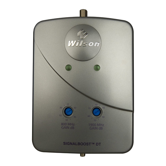
Page 11: Understanding The Indicator Lights
Contact Wilson Electronics Technical Support Team with any questions at 866-294-1660 or email: tech@wilsonelectronics.com. Hours: 7 am to 6 pm MST. -
Page 12: Warnings And Recommendations
The SIGnALBOOST DT is not designed for iDEn/nextel frequency, however, Wilson Electronics offers specific Signal Boosters for iDEn/nextel users . Visit www.WilsonElectronics.com for details . Contact Wilson Electronics Technical Support Team with any questions at 866-294-1660 or email: tech@wilsonelectronics.com. Hours: 7 am to 6 pm MST. - Page 13 Antenna . Signal Optional Panel Antenna Booster (with cable) for improved coverage inside the building (Wilson part # 301147) Contact Wilson Electronics Technical Support Team with any questions at 866-294-1660 or email: tech@wilsonelectronics.com. Hours: 7 am to 6 pm MST.
-
Page 14: About Wilson Electronics
Wilson Electronics, Inc . for any business or personal losses arising from its use, or for any infringements of patents or other rights of third parties that may result from its use . Contact Wilson Electronics Technical Support Team with any questions at 866-294-1660 or email: tech@wilsonelectronics.com. Hours: 7 am to 6 pm MST. -
Page 15: Guarantee And Warranty
One or more of the following U .S . Patent numbers may apply to the Signal Booster in this product – D596,614; D596,615; D563,381;7,729,669; 7,486,929; 7,729,656; 7,409,186; 7,783,318; 7,684,838; 12,714,994 . Contact Wilson Electronics Technical Support Team with any questions at 866-294-1660 or email: tech@wilsonelectronics.com. Hours: 7 am to 6 pm MST. -
Page 16: Signal Booster Specifications
Signal Booster Specifications SIGnalBooST™ DT Specifications Model number 271265 Outside antenna connectors F-Female / SMA-Female Outside antenna impedance 75 / 50 Ohms Inside antenna connectors Inside antenna impedance 50 Ohms Dimensions 6 .5 x 4 .5 x 1 .75 inch (16 .5 x 11 .4 x 4 .4 cm) Weight 0 .47 lbs (0 .213 kg) Frequency...
Need help?
Do you have a question about the signalboost dt 271265 and is the answer not in the manual?
Questions and answers