Table of Contents
Advertisement
Quick Links
Download this manual
See also:
Instruction Manual
Advertisement
Table of Contents

Summary of Contents for Kuzma 4POINT
- Page 1 Instruction manual KUZMA 4POINT 14 inch TONEARM Serial Number: ….. 2016-09...
-
Page 2: Table Of Contents
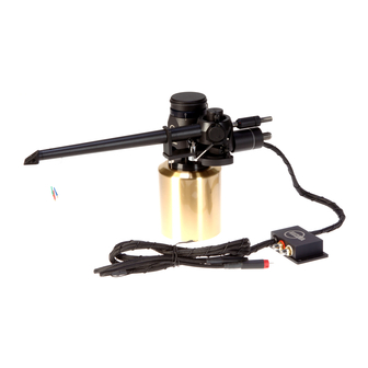
KUZMA LTD INSTRUCTION MANUAL FOR 4POINT 14 tonearm The 4POINT 14 tonearm is a very precisely engineered piece of equipment, however, the construction is robust and requires minimal maintenance for optimal performance. It differs from standard 4Point due almost 3 inches longer tube. It this requires different mounting distance. -
Page 3: General Description
1.4 m long tonearm cable with silver bullet connectors. Product registration and warranty extension Kuzma products have a non transferable 2 year limited warranty on parts and labour, which may vary in each country. To obtain the 5 year limited warranty from us, you need to register the product on our web site within 30 days of purchase. -
Page 4: Technical Data
340 mm ( 338-348 mm) Effective mass: 19 g VTA adjustment: Azimuth adjustment: Bias adjustment: Vertical damping: Horizontal damping: Detachable headshell: yes ( one extra supplied) Cables: silver Arm mount: Kuzma cut Optional: extra headshells, headshell containers, different wiring option... -
Page 5: Unpacking And Basic Setup
1. Unpacking Open the box carefully and remove top covers. The tube with vertical bearing points is packed separately (tube assembly) on the top of the box. Please do handle with care and when put aside, ensure that nothing is touching the bearing points. Bear in mind how you will handle tube with output cable. - Page 6 With 1.5 mm Allen key, release the height ring ( Fig. 3.) which is on the fixing pillar below the VTA arm tower. Now it will drop down and touch the armbase. Fix the ring again and release the VTA arm tower.
-
Page 7: Setting Up The Tonearm
3. Setting up the tonearm Connecting tonearm: Check the horizontal movement of the tube to ensure that the headshell will reach the inner grooves (approximately to the edge of record label), but will not travel to the centre of the record. Also check the arm wire loop and connect the tonearm cable into the phono sockets of the preamp. - Page 8 Balancing of the tonearm: Fix cartridge pins. Add extra counterweights to the lower threaded carrier as per chart below, until the tonearm is roughly balanced. Fig. 9. Knowing the approximate mass of the cartridge( add aprox 1 gr for screws and 1 gr for fingerlift), enables choice of the correct configuration of different counterweights.
-
Page 9: Adjustment Of Tracking Force
zero is very difficult. Adjust it to be roughly balanced and increase tracking force with upper smaller counterweight. If this is too loose, hold the front part of the counterweight and rotate the rear part until there is a tighter fit, or lock it into position on the threaded carrier. Opposite rotation will make the smaller counterweight looser. -
Page 10: Adjustment Of Vta
Fig. 10. VTA tower side-rough scale 7. Adjustment of azimuth To make azimuth adjustments, release the two screws locking the mechanism at the centre top of the main tonearm tube, with Allen key 2mm. Under the main tube is a tiny rod with a hexagonal screw. Insert the Allen key 2 mm into the screw (it may feel loose), rotate it slightly and it will alter the azimuth. -
Page 11: Adjustment Of Bias
Fig. 11A Bias distance “X” For maximum tracking, it is advisable to set the bias by use of an appropriate test record, ie. those with tracking bands. Please do not use test records with blank space where the tip of the needle sits on the surface rather than in the groove. -
Page 12: Adjustment Of Cueing Device
Adding damping oil: First insert silicone damping oil into the troughs. Let the liquid settle, before adding more. Stop filling, when you reach the silver lines about 3mm below the edge of the troughs. Removing trough: Removing trough using Allen keys 1.5 mm (vertical- Fig .13) and 2.5 mm (horizontal- Fig.14). Release fixing screw and pull away trough. -
Page 13: Maintenance
2B: Cartridge is not reaching inner grooves: check that position of the tonearm is correct with protractor for distance 344 mm and spindle to armbase distance is 291 mm. 3. Headshell cannot be removed- check that the screw is released enough with Allen key. Kuzma Ltd Hotemaze 17A SI-4205 PREDDVOR...


Need help?
Do you have a question about the 4POINT and is the answer not in the manual?
Questions and answers