Avigilon H3-DC1 Installation Manual
High definition h.264 ip dome camera
Hide thumbs
Also See for H3-DC1:
- User manual (192 pages) ,
- Web interface user manual (35 pages) ,
- User manual (26 pages)
Table of Contents
Advertisement
Quick Links
Download this manual
See also:
User Manual
Advertisement
Table of Contents

Related Manuals for Avigilon H3-DC1


Summary of Contents for Avigilon H3-DC1
-
Page 1: Installation Guide
Installation Guide Avigilon™ High Definition H.264 IP Dome Camera Models: H3-DC1, H3-DC2, H3A-DC1 and H3A-DC2... - Page 2 Power Source” with output rated 12 VDC or 24 VAC, 6 W min. or Power over Ethernet (PoE), rated 48 VDC, 6 W min. Any external power supply connected to this product may only be connected to another Avigilon product of the same model series. External power connections must be properly insulated. ...
-
Page 3: Fcc Notice
Consult the dealer or an experienced radio/TV technician for help. Changes or modifications made to this equipment not expressly approved by Avigilon Corporation or parties authorized by Avigilon Corporation could void the user’s authority to operate this equipment. Disposal and Recycling Information When this product has reached the end of its useful life, please dispose of it according to your local environmental laws and guidelines. - Page 4 © 2012 - 2015, Avigilon Corporation. All rights reserved. AVIGILON, the AVIGILON logo, and AVIGILON CONTROL CENTER are trademarks of Avigilon Corporation. Other product names mentioned herein may be the trademarks of their respective owners. The absence of the symbols ™ and ® in proximity to each trademark in this product or its packaging is not a disclaimer of ownership of the related trademark.
-
Page 5: Table Of Contents
Table of Contents Overview Cover View Bottom View Front View Rear View Installation Required Tools and Materials Camera Package Contents Installation Steps Removing the Dome Cover Mounting the Dome Camera Connecting Cables Assigning an IP Address Accessing the Live Video Stream Aiming the Dome Camera (Optional) Configuring Onboard Storage Installing the Dome Cover... -
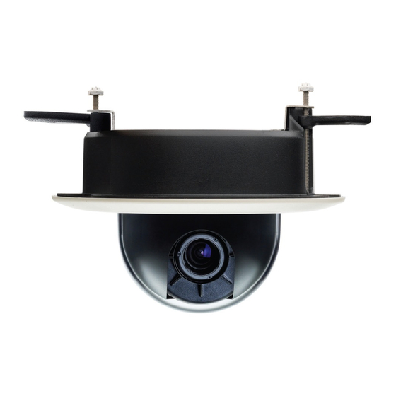
Page 6: Overview
Overview Cover View 1. Dome Cover Vandal proof dome cover. 2. Tamper Resistant Screws Torx captive screws to fix the dome cover to the base. Overview... -
Page 7: Bottom View
Bottom View 1. Cable Entry Hole An entry hole for network, power and I/O cables. 2. Ceiling Panel Clamps Clamps for securing the dome camera to the ceiling panel. 3. Serial Number Tag Product serial number and part number label. Bottom View... -
Page 8: Front View
Front View 1. Azimuth Control Provides adjustment of the image angle. 2. Tilt Lock Thumb Screws Provides a locking mechanism for the image tilt adjustment. 3. Pan Lock Thumb Screws Provides a locking mechanism for the image pan adjustment. 4. I/O Connector Block Provides connections to external input/output devices. -
Page 9: Rear View
Accepts an Ethernet connection to a network. Server communication and image data transmission occurs over this connection. Also receives power when it is connected to a network that provides Power over Ethernet. 8. Connection Status LED Provides information about device operation. For more information, see LED Indicators on page 13 9. -
Page 10: Installation
Small slotted screwdriver with 5/64” or 2 mm blade width — for connecting power when not using Power over Ethernet. Camera Package Contents Ensure the package contains the following: Avigilon™ High Definition IP Dome Camera Terminal block T20 Torx key ... -
Page 11: Mounting The Dome Camera
the installation is complete. Mounting the Dome Camera CAUTION — This camera is designed for indoor use only. Perform the following steps to mount the dome camera to the ceiling: 1. Use the hole template to cut a 140 mm (5.5”) hole in a ceiling panel. 2. -
Page 12: Connecting Cables
CAUTION — The ceiling material must be able to sustain a minimum of 0.6 kg (1.2 lbs). Connecting Cables Refer to the diagrams in the Overview section for the location of the different connectors. To connect the cables required for proper operation, complete the following: 1. -
Page 13: Assigning An Ip Address
Web browser interface: http://<IP address>/ Network Video Management software application (for example, the Avigilon Control Center software). NOTE: The default camera username is admin and the default camera password is admin. Aiming the Dome Camera 1. Loosen the pan and tilt lock screws on the camera. -
Page 14: Installing The Dome Cover
Additional information about setting up and using the device is available in the following guides: Avigilon™ Control Center Client User Guide Avigilon™ High Definition H.264 Web Interface User Guide The manuals are available on the Avigilon website: http://avigilon.com/support-and-downloads Installing the Dome Cover... -
Page 15: Cable Connections
Cable Connections Connecting External Power NOTE: Do not perform this procedure if Power over Ethernet (POE) is used. If PoE is not available, the device needs to be powered through the removable power connector block. Refer to the diagrams in this guide for the location of the power connector block. The device can be powered from 12 V DC or 24 V AC. -
Page 16: Connecting To Microphones, Speakers And Video Monitors
1. Ground 2. Input — To activate, connect the Input to the Ground pin. To deactivate, leave disconnected or apply between 3-15 V. 3. Output — When active, Output is internally connected with the Ground pin. Circuit is open when inactive. Maximum load is 25 VDC, 120 mA. - Page 17 Figure 1: Mini-jack audio video connector 1. Audio IN 2. Composite Video OUT 3. GND 4. Audio OUT Connecting to Microphones, Speakers and Video Monitors...
-
Page 18: Led Indicators
LED Indicators Once connected to the network, the Connection Status LED will display the progress in connecting to the Network Video Management software. The following table describes what the LEDs indicate: Connection Status Connection State Description One short flash every Obtaining IP Address Attempting to obtain an IP address. -
Page 19: Resetting To Factory Default Settings
Resetting to Factory Default Settings If the camera no longer functions as expected, you can choose to reset the camera to its factory default settings. Use the firmware revert button to reset the camera. Figure 2: The firmware revert button on the side of the dome camera. 1. -
Page 20: Setting The Ip Address Using The Arp/Ping Method
Setting the IP Address Using the ARP/Ping Method Complete the following steps to configure the camera to use a specific IP address: 1. Locate and copy down the MAC Address (MAC) listed on the Serial Number Tag for reference. 2. Open a Command Prompt window and enter the following commands: a. -
Page 21: Cleaning
Cleaning Dome Bubble If the video image becomes blurry or smudged in areas, it may be because the dome bubble requires cleaning. To clean the dome bubble: Use hand soap or a non-abrasive detergent to wash off dirt or finger prints ... -
Page 22: Specifications
Specifications Camera Audio Input Line input, A/V mini-jack (3.5 mm) Video Output NTSC/PAL, A/V mini-jack (3.5 mm) H3-DC1: 3-9mm, F1.2, P-iris Lens H3-DC2: 9-22mm, F1.6, P-Iris Onboard Storage SD/SDHC/SDXC slot – minimum class 4; class 6 or better recommended Network... - Page 23 Environmental Operating -10 °C to +50 °C (14 °F to 122 °F) Temperature Storage -10 °C to +70 °C (14 °F to 158 °F) Temperature Humidity 0-95% non-condensing Certifications ROHS Certifications WEEE KC (C-H3A-DC models only) UL 60950-1 Safety CSA 60950-1 IEC/EN 60950-1 FCC Part 15 Subpart B Class B EN 55022 Class B...
-
Page 24: Limited Warranty & Technical Support
Limited Warranty & Technical Support Avigilon warrants to the original consumer purchaser, that this product will be free of defects in material and workmanship for a period of 3 years from date of purchase. The manufacturer’s liability hereunder is limited to replacement of the product, repair of the product or replacement of the product with repaired product at the discretion of the manufacturer.
Need help?
Do you have a question about the H3-DC1 and is the answer not in the manual?
Questions and answers