
Related Manuals for Binary B-520-MTRX-230-8x8


Summary of Contents for Binary B-520-MTRX-230-8x8
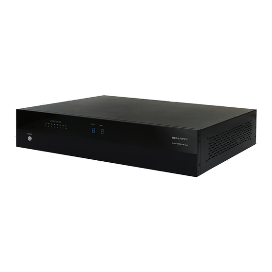
- Page 1 HDMI MATRIX SWITCHER B-520-MTRX-230-8x8 B-520-MTRX-230-6x4+2 INSTALLATION MANUAL Source | M (HDMI Ou...
- Page 2 IMPORTANT SAFETY INSTRUCTIONS To reduce the risk of fire or electric shock, read and follow all instructions and warnings in this manual. Keep this manual for future reference. 1. Do not expose this apparatus to rain or moisture. Do not expose this equipment to dripping or splashing, and ensure that no objects filled with liquids, such as vases, are placed on the equipment.
-
Page 3: Table Of Contents
3. Package Contents ....................................................4 4. Recommended for Installation ................................................5 5. Device Layout ......................................................5 5.1. Front Panel of the B-520-MTRX-230-8x8 Switcher ....................................5 5.2. Rear Panel of the B-520-MTRX-230-8x8 Switcher ....................................6 5.3. Front Panel of the B-520-MTRX-230-6x4+2 Switcher ..................................... 7 5.4. -
Page 4: Product Overview
1. PRODUCT OVERVIEW Welcome to Binary™. This product is engineered to provide years of exceptional reliability. We appreciate your business, and we stand committed to providing our customers with the highest degree of quality and service in the industry. The B-520-MTRX-230-8x8 / B-520-MTRX-230-6x4+2 is a state-of-the-art HDMI matrix switcher with both HDMI and HDBaseT outputs. -
Page 5: Recommended For Installation
Binary High Speed HDMI Cables to connect sources to B-520-MTRX-230-8x8/B-520-MTRX-230-6x4+2 HDMI inputs • Binary HDMI cables or B-520-RX-230-IR units and Category cable installed between matrix switcher location and displays (See section 7.6.3.1, page 10 for HDBaseT wiring recommendations) • RJ45 connectors and termination tools (if using B-520-RX-230-IR) •... -
Page 6: Rear Panel Of The B-520-Mtrx-230-8X8 Switcher
Connect HDMI cables to route to displays. Output simultaneously displays the same source as the HDBaseT output of the same number K. Ethernet Port RJ45 port for connecting an ethernet Cat5e/6 cable for IP control of the B-520-MTRX-230-8x8 L. HDMI Inputs (1 through 8) Connect HDMI cables from sources to the matrix switcher for distribution... -
Page 7: Front Panel Of The B-520-Mtrx-230-6X4+2 Switcher
5.3. Front Panel of the B-520-MTRX-230-6x4+2 Switcher FIGURE 3: B-520-MTRX-230-6x4+2 Switcher Layout (Front View) A. Power On/Off Switch Lights up blue when power is on and lights up red when in stand-by. Can be disabled from Configuration Utility software B. Source Status LEDs Indicates that the selected source is on and transmitting an HDMI signal C. -
Page 8: Rear Panel Of The B-520-Mtrx-230-6X4+2 Switcher
5.4. Rear Panel of the B-520-MTRX-230-6x4+2 Switcher FIGURE 4: B-520-MTRX-230-6x4+2 Switcher Layout (Rear View) A. Power LED Lights up red when power is Applied B. Power Jack +12V DC, 16A power supply connection C. RS-232 control port (DB9) To communicate with control system or Windows PC for serial control of matrix D. -
Page 9: Installation & Setup
6. INSTALLATION & SETUP 6.1. Basic Installation Diagram Complete the basic installation section to set up the matrix switcher for media distribution before completing any other setup. Use this diagram for reference during basic installation of the matrix switcher, sources, displays and wiring. Cable/Sat Box Blu-ray Player Control System... -
Page 10: Basic Instructions
Leave an RS-232 connection easily accessible for using the Configuration Utility. The B-520-MTRX-230-8x8 / B-520-MTRX-230-6x4+2 is equipped with many setup functions that must be accessed by using a PC and the Configuration Utility. Leave an RS-232 cable connected during setup and testing that can easily be connected to the PC. -
Page 11: Switcher Location And Placement
Remove the screws for the feet with a #2 Phillips Screwdriver and store the feet and screws together in case they are needed in the future. Note: The rack ears and mounting holes are only designed to safely hold the weight of the B-520-MTRX-230-8x8 / B-520-MTRX-230-6x4+2. -
Page 12: Output Connections
6.6. Output Connections The B-520-MTRX-230-8x8 / B-520-MTRX-230-6x4+2 is equipped with HDMI and HDBaseT output ports. See the sections below for specific instructions and details for each connection type. Note: Any input selected on an output zone is played on both the HDMI and HDBaseT outputs for that zone simultaneously. -
Page 13: Installation Instructions
Note: For IR Passthrough integration, see section 7.8. IR Passthrough Installation and Setup, page 12. 6.7. Matrix Control Connections All drivers, associated software and extra documentation is available under the Support tab on the B-520-MTRX-230-8x8 / B-520-MTRX-230-6x4+2 product page at www.SnapAV.com IR IN ALL IR OUT... -
Page 14: Rs-232 Control
6.7.2. RS-232 Control To control the B-520-MTRX-230-8x8 / B-520-MTRX-230-6x4+2 with RS-232, the devices must connect using the correct pin configuration for the control system in use. The matrix switcher receives control data on pin 2 (RxD – Data Receive) and transmits control data on pin 3 (TxD-Data Transmit). -
Page 15: Matrix Switcher Ir Connections
HDBaseT port. 6.8.2. Matrix Switcher IR Port Configuration All IR connection ports on the B-520-MTRX-230-8x8 / B-520-MTRX-230-6x4+2 are 3.5mm mono and use this pinout configuration. Note: Consult with the manufacturer of any attached IR equipment to confirm their pinout matches before use. -
Page 16: B-520-Rx-230-Ir Ir Connections
6.9. B-520-RX-230-IR IR Connections The B-520-RX-230-IR IR ports are described below. Use the diagram for reference. Flasher Receiver HDMI OUT FIGURE 12 A. IR Flasher–IR output to connect to IR Flasher B. IR Receiver–IR input to connect to IR Receiver or to output of a control system 6.9.1. -
Page 17: Ir Application Diagrams
6.10. IR Application Diagrams 6.10.1. IR Passthrough from Control System Ethernet Connection IR Flasher IR Flasher Cat 5e/6 RS 232 IR Outputs IR Inputs PLAY Control System HDMI Source HDMI Source RS-232 Cable 3.5mm Mono HDMI HDMI B-520-MTRX-230 -8x8 Cat 5e/6 AC Power 12V DC INPUT... - Page 18 The diagram on page 17 illustrates a typical installation with a B-520-MTRX-230-8x8 / B-520-MTRX-230-6x4+2 where all of the equipment is being controlled by a control system. • The control system sends commands to each device being controlled. Custom programming by the installer sets the control system up to automatically switch inputs and outputs in the matrix switcher as needed, so the end user only has to select the source they want to watch.
-
Page 19: Ir Passthrough From Rooms To Sources
IR Receiver HDMI Projector IR Receiver HDTV IR Receiver FIGURE 17: IR Passthrough The diagram above illustrates a typical installation with a B-520-MTRX-230-8x8 / B-520-MTRX-230-6x4+2 where all of the equipment is being controlled by IR remotes in each output zone. -
Page 20: Edid Configuration
It is necessary to make sure sources will provide a video and audio format compatible with all connected displays programmed to use them. To accomplish this, the B-520-MTRX-230-8x8 / B-520-MTRX-230-6x4+2 includes built-in EDID management for each source input. The stored EDID is per source, so all display locations will see the same resolution and have the same audio format when that source is selected. -
Page 21: Display Setup
7.4. Embedded EDID Configuration In addition to the automatic configuration method, EDIDs in the B-520-MTRX-230-8x8 / B-520-MTRX-230-6x4+2 can be set to inputs manually by selecting an EDID from the embedded list (default EDIDs programmed into the matrix switcher). The matrix switcher contains eight ‘embedded’ EDIDs that may be assigned to inputs. These EDIDs define groups of video and audio capabilities that are useful for configuring sources in most systems. -
Page 22: How To Set Embedded Edid For A Single Input
Explanation of Embedded EDIDs Video Resolution in the Embedded EDIDs is the highest resolution a connected source will output. That is, if the source is capable of 1080P@60 it will be required by EDIDs 1-6 to provide that resolution. However, if the source is only capable of 1080i it will output 1080i, etc. -
Page 23: How To Learn Edid To A Single Input
When to Use Learned EDIDs • An older display does not work properly with any of the embedded EDIDs. • When the source is a PC it may be necessary to use a learned EDID. • Learning EDID to a single input 7.5.1. -
Page 24: Advanced Setup Using The Configuration Utility
This setting controls the operation of the front panel IR receiver built into the B-520-MTRX-230-8x8 / B-520-MTRX-230-6x4+2. This should be disabled if using the SYSTEM IR IN port to control the matrix switcher via IR, or if the matrix switcher is missing or receiving extra commands during use (stray IR interfering with the port). -
Page 25: Firmware Update
9. FIRMWARE UPDATE Binary may occasionally release new firmware for the B-520-MTRX-230-8x8 / B-520-MTRX-230-6x4+2 to address new standards and technology. It will never be necessary to perform an update to an existing, correctly functioning system, but during installation or service, it is recommended to check the installed version to be sure it is the newest available. -
Page 26: Route Inputs To Outputs
10.1.1. Route Inputs to Outputs Input to Single Output Display Readout (Example) Example: Output=3 Input=4 1. Press OUTPUT 2. Press Number Key (1-8) to select Output 3. Press INPUT 4.Press Number Key (1-8) to select Input 5. Press ENTER Input to All Outputs Display Readout (Example) Example: Output=All Input=4 1. -
Page 27: Resetting To Factory Defaults
1.1 before attempting further setup or use. 11. TROUBLESHOOTING If issues arise during installation or testing of the B-520-MTRX-230-8x8 / B-520-MTRX-230-6x4+2, follow these guidelines to troubleshoot. Use the System Layout chart on the next page to record a description of each part of the system. -
Page 28: No Signal From Source To Any Display
11.2. No Signal from Source to any Display If a source will not send a signal to any connected display, it is probably due to an issue with the cable in use, the EDID setting for the input, or the settings in the source: •... -
Page 29: System Layout Chart
12. SYSTEM LAYOUT CHART Use this chart to identify the sources and displays attached to the system, and make any notes about each part. When completing the outputs chart, make sure to indicate whether an HDMI cable, B-520-RX-230-IR, or another brand HDBaseT receiver is being used to extend signal to the display, and indicate the approximate length of any cables. -
Page 30: Specifications
13. SPECIFICATIONS TECHNICAL HDMI Compliance HDMI 3D HDCP Compliance Video Bandwidth 6.75Gbps HDMI over UTP Resolution Cat5e/6 Cat6a/7 Transmission 1080i / 720p 24-bit color 200ft 230ft Full HD 1080P 24-bit 200ft 230ft color Full HD 1080P 36-bit 200ft 230ft deep color Input TMDS Signal 1.2 Volts (peak-to-peak) Input DDC Signal... -
Page 31: Contacting Tech Support
15. WARRANTY 2 Year Limited Warranty This Binary product has a 2-Year limited warranty. This warranty includes parts and labor repairs on all components found to be defective in material or workmanship under normal conditions of use. This warranty shall not apply to products that have been abused, modified or disassembled. Products to be repaired under this warranty must be returned to SnapAV or a designated service center with prior notification and an assigned return authorization number (RA).. - Page 32 ® Rev: 151117-0935...
Need help?
Do you have a question about the B-520-MTRX-230-8x8 and is the answer not in the manual?
Questions and answers