
Related Manuals for Binary B-500-MTRX-230-4x4


Summary of Contents for Binary B-500-MTRX-230-4x4
- Page 1 Binary™ HDMI Matrix Switcher Installation Manual with HDMI and HDBaseT Outputs B-500-MTRX-230-4x4...
-
Page 2: Important Safety Instructions
B-500-MTRX-230-4x4 Installation Manual 1. Important Safety Instructions Warning: To reduce the risk of fire or electric shock, do not expose this apparatus to rain or moisture. Do not remove cover. No user serviceable parts inside. Refer servicing to qualified service personnel. 1. Read and follow all instructions and warnings in this manual. Keep for future reference. 2. Do not use this apparatus near water. 3. Clean only with a dry cloth. 4. Do not block any ventilation openings. Install according to manufacturer’s instructions. 5. Do not install near any heat sources such as radiators, heat registers, stoves or other apparatus (including amplifiers) that produce heat. 6. Do not override the safety purpose of the polarized or grounding-type plug. A polarized plug has two blades - one wider than the other. A grounding type plug has two blades and a third grounding prong. The wide blade or the third prong is provided for your safety. If the provided plug does not fit into your outlet, consult an electrician for replacement of the obsolete outlet. 7. Protect the power cord from being walked on or pinched particularly at plug, convenience receptacles, and the point where it exits from the apparatus. 8. Only use attachments/accessories specified by the manufacturer. 9. Refer all servicing to qualified service personnel. Servicing is required when the apparatus has been damaged in any way, such as when the power-supply cord or plug is damaged, liquid has been spilled or objects have fallen into the apparatus, the apparatus has been exposed to rain or moisture, does not operate normally, or has been dropped. -
Page 3: Table Of Contents
B-500-MTRX-230-4x4 Installation Manual Table of Contents Important Safety Instructions Product Overview Package Contents Features Recommended for Installation Device Layout 6.1. Front Panel 6.2. Rear Panel Installation Setup 7.1. Basic Installation Diagram 7.2. Basic Instructions 7.3. Installation Tips 7.4. Switcher Location and Placement 7.4.1. Rack Installation 7.5. HDMI Input Connections 7.6. Output Connections 7.6.1. -
Page 4: Product Overview
RS232, this product is ideal for residential and commercial media distribution systems. The HDBaseT connection on each output extends HDMI signals and bi-directional IR to remote rooms up to 230 feet away via Cat5e/Cat6/Cat6a. Note: This manual covers all aspects of installation and setup of the B-500-MTRX-230-4x4 for most applications. Some features must be configured using the Configuration Utility software. Go to the product page for the B-500-MTRX- 230-4x4 at www.SnapAV.com and click on the Support Tab to download the Configuration Utility and manual. -
Page 5: Device Layout
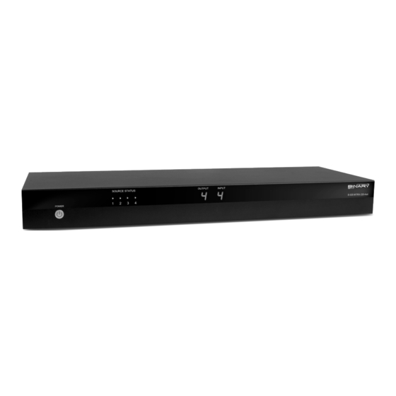
B-500-MTRX-230-4x4 Installation Manual 6. Device Layout 6.1. Front Panel 1. Power On/Off Switch Toggle Power from On to Stand-by. Can be disabled from Configuration Utility software. 2. Source Status LEDs Indicates that the selected source is on and transmitting an HDMI signal. 3. Output Display Displays the last output selected. 4. IR Receiver Window IR receiver for Matrix to capture commands sent by IR remote. 5. Input Display Displays the last input selected. Pg. 5 www.snapav.com Support: 866.838.5052... -
Page 6: Rear Panel
B-500-MTRX-230-4x4 Installation Manual 6.2. Rear Panel 24V DC 2.7A LINK LINK LINK LINK 1. HDMI Inputs 1 through 4 Connect HDMI cables from sources to the matrix switch for distribution. 2. RS-232 control port (DB9) Attach connection from control system or Windows PC for serial control of the B-500-MTRX-230-4X4. 3. IR Output to Source 1 through 4 3 .5mm mono mini connections used to connect IR flashers for controlling sources. These ports may be configured to route commands only from the IR output corresponding to the HDBaseT output number (IR zone routing), or directly to the source selected for viewing on an HDBaseT output (IR source routing). (See Configuration Utility) 4. RJ45 HDBaseT Outputs 1 through 4 Connect 568B terminated Cat5e/6 HDBaseT cable routed to a B-500-RX-230-IR up to 230 feet away to feed HDMI signal to display. Output simultaneously displays the same source as the HDMI output of the same number. -
Page 7: Installation And Setup
B-500-MTRX-230-4x4 Installation Manual 7. Installation and Setup 7.1. Basic Installation Diagram Complete the basic installation section to set up the matrix switcher for media distribution before completing any other setup. Use this diagram for reference during basic installation of the matrix switcher, sources, displays and wiring. HDMI Blu-ray Player Cable/Sat Box HDMi Game Home Automation System Console HDMI HDMI RS232 24V DC 2.7A LINK LINK LINK LINK Cat5e/6 HDMI HDMI AC Power AC Power... -
Page 8: Installation Tips
Screwdriver, and store the feet and screws together in case they are needed in the future. Note: The rack ears and mounting holes are only designed to safely hold the weight of the B-500-MTRX-230-4x4. Do not use the matrix switcher as a shelf for other equipment in the rack. Pg. 8 © 2013 Binary... -
Page 9: Hdmi Input Connections
B-500-MTRX-230-4x4 Installation Manual 7.5. HDMI Input Connections Each of the four inputs on the B-500-MTRX-230-4X4 utilizes a standard HDMI port for connection. Follow these guidelines when connecting sources to the inputs. • A lways use the shortest cable possible between source equipment and the matrix switcher inputs. Use high speed rated cables to guarantee the best possible performance. • Avoid using HDMI cable adapters in runs. Always run one unbroken cable when possible. 7.6. Output Connections The B-500-MTRX-230-4X4 matrix switcher is equipped with one HDMI and one HDBaseT output port for each of the 4 output zones. See the sections below for specific instructions and details for each connection type. Note: Any input selected on an output zone is played on both the HDMI and HDBaseT outputs for that zone simultaneously. -
Page 10: Hdbaset Outputs
B-500-MTRX-230-4x4 Installation Manual 7.6.3. HDBaseT Outputs Follow these guidelines when selecting and installing the HDBaseT cable, and then follow the instructions afterward to complete the connections for an output. 7.6.3.1. HDBaseT Wiring Recommendations Cable Type- Shielded or Unshielded Cat5e/6 • Cable Distance Limitations: Cat5e/ Cat6: Up to 200 ft Cat6a: Up to 230 ft • U se at least Category 5e high-quality twisted pair solid conductor cable rated to no less than 350 Mhz bandwidth. The higher the cable standard, the better it will perform. • F or the best results install a shielded cable. This will prevent signal dropout and artifacts from being caused by electromagnetic and radio interference (EMI/RFI) from ceiling fans, appliances and electric motors. -
Page 11: Matrix Control Connections
All drivers, associated software and extra documentation is available on the B-500-MTRX-230-4X4 product page at www.SnapAV.com under the Support Tab. 7.7.1. IR Control The B-500-MTRX-230-4X4 can be controlled by IR from the front panel receiver or by attaching a mono cable from the control system flasher output to the “System IR In” port IR IN ALL IR OUT Matrix IR on the back of the matrix switcher. For the most reliable control, use the System IR In port. -
Page 12: Ir Pass-Through Installation And Setup
B-500-MTRX-230-4x4 Installation Manual 7.8. IR Pass-Through Installation and Setup To utilize IR pass-through between a display location and the matrix switcher, install a B-500-RX-230-IR at the display and use HDBaseT for routing the signal. The matrix switcher and the matrix receiver are equipped with ports to allow commands to be sent to the display or from the display area. This section details the pinouts and correct use of the IR pass-through ports. 7.8.1. Matrix Switcher IR Connections The ports indicated in the diagram are described in detail below. Guides for standard applications are included on the following pages for reference during setup. LINK LINK LINK LINK 1. IR Output to Source 1 through 4 T he IR output from each connected B-500-RX-230-IR is transmitted to the IR OUTPUT TO SOURCE ports. Commands can be routed to the source selected or to the like-numbered port. 2. IR Input to Room 1 through 4 U se 3.5mm mini-mono cables to connect IR flasher outputs on a control system to these ports to send commands... -
Page 13: B-500-Rx-230-Ir Ir Connections
B-500-MTRX-230-4x4 Installation Manual 7.9. B-500-RX-230-IR IR Connections The B-500-RX-230-IR IR ports are described below. Use the diagram for reference. 7.9.1. IR Receiver Attach an IR receiver to this port to capture IR commands in the room for pass-through for sources. This port will also send commands back to the matrix switcher for control of source selection in each zone. 12V DC (Sleeve) IR Signal GND (Ring) GND (Ground) Ring IR Signal (Tip) +12V DC Sleeve 7.9.2. IR Flasher Attach an IR flasher to this port for controlling a display or other equipment with commands sent from a control system flasher output, into the matrix switcher IR INPUT TO ROOM ports and then to this port. GND (Sleeve) IR Signal IR Signal (Tip) -
Page 14: Ir Application Diagrams
B-500-MTRX-230-4x4 Installation Manual 7.10. IR Application Diagrams 7.10.1. IR Pass-Through from Control System RS232 IR Flasher IR Flasher HDMI Source HDMI Source IR Outputs IR Inputs RS232 C5e/6 Ethernet Connection PLAY 3.5mm Mono 24V DC 2.7A LINK LINK LINK LINK... -
Page 15: Ir Pass-Through From Rooms To Sources
B-500-MTRX-230-4x4 Installation Manual 7.10.2. IR Pass-Through from Rooms to Sources HDMI Source HDMI Source PLAY IR Flasher IR Flasher HDMI HDMI 24V DC 2.7A LINK LINK LINK LINK Cat5e/6 Cat5e/6 IR Receiver B-500-RX-230-IR B-500-RX-230-IR HDMI IR Receiver HDMI Projector IR Receiver... -
Page 16: Edid Configuration
B-500-MTRX-230-4x4 Installation Manual 8. EDID Configuration The displays used within an installation usually vary from room to room, and some may not support all resolutions available from a source. It is necessary to make sure sources will provide a video and audio format compatible with all connected displays programmed to use them. To accomplish this, the B-500-MTRX-230-4X4 includes built-in EDID management for each source input. The stored EDID is per source, so all display locations will see the same resolution and have the same audio format when that source is selected. Note: Source is only able to output one video resolution and one audio format. -
Page 17: Embedded Edid Configuration
B-500-MTRX-230-4x4 Installation Manual 8.4. Embedded EDID Configuration In addition to the automatic configuration method, EDIDs in the B-500-MTRX-230-4X4 can be set to inputs manually by selecting an EDID from the embedded list (default EDIDs programmed into the matrix switcher). The matrix switcher contains eight ‘embedded’ EDIDs that may be assigned to inputs. These EDIDs define groups of video and audio capabilities that are useful for configuring sources in most systems. 8.4.1. Embedded EDID Chart Embedded EDID Resolution Color Depth Audio 1080p@60Hz 24-Bit 7.1ch 2 (Factory Default) 1080p@60Hz 24-Bit 1080p@60Hz 24-Bit 3D 7.1ch 1080p@60Hz 24-Bit 3D 1080i@60Hz 36-Bit 3D 7.1ch 1080i@60Hz 36-Bit 3D 1080i@30Hz / 720p@60Hz 24-Bit 7.1ch... -
Page 18: How To Set Embedded Edid For A Single Input
B-500-MTRX-230-4x4 Installation Manual 8.4.2. How to Set Embedded EDID for a Single Input Example: Input =1 Embedded EDID=4 Display Readout (Example) 1. Press DEFAULT 2. Press Number Key (1-8) to select one Embedded EDID 3. Press INPUT 4. Press Number Key (1-4) to select the Input to which the EDID is applied (success) 5. Press ENTER (fail) 8.4.3. How to Set Embedded EDID for All Inputs... -
Page 19: How To Learn Edid To A All Inputs
B-500-MTRX-230-4x4 Installation Manual 8.5.2. How to Learn EDID to All Inputs Example: Input=All EDID Learned from Output 4 Display Readout (Example) 1. Press LEARN 2. Press OUTPUT 3. P ress Number Key (1-4) to select the Output the EDID is learned from (success) 4. Press ENTER (fail) 8.6. Viewing Input EDID Status If there is a question about the EDID set for an input, the status of that input’s EDID can be reviewed using the included IR remote and watching the matrix switcher front panel display. Display Readout (Example) Example: View the EDID for Input 3. -
Page 20: Advanced Setup Using The Configuration Utility
IR remote or commands learned from it. Go to the Support Tab of the B-500-MTRX-230-4X4 product page at www.SnapAV.com to see and download the available IR codes and drivers for IR remote programming. -
Page 21: Operation And Control
B-500-MTRX-230-4x4 Installation Manual 11. Operation and Control During setup and testing, use the included IR remote to control the matrix switcher. After setup is complete, a control method should have been set up and programmed as described in Section 7.7. Matrix Control Connections for regular operation. 11.1. IR Remote This section describes the correct button-push sequences to perform regular operations with the IR remote. The ENTER key must be pressed within 10 seconds of the last command in order to be processed. Function POWER Power on the matrix switcher Enter standby mode OUTPUT Number Keys Select a number INPUT... -
Page 22: Turn Off (Mute) Outputs
B-500-MTRX-230-4x4 Installation Manual Input to All Outputs Display Readout (Example) Example: Output=All Input=4 1. Press OUTPUT 2. Press ALL to select all Outputs 3. Press INPUT 4. Press Number Key (1-4) to select Input 6. Press ENTER 11.1.2. Turn Off (Mute) Outputs Mute one Output Example: Output=1 Display Readout (Example) 1. Press OUTPUT 2. Press Number Key (1-4) to select Output 3. Press OUTPUT OFF 4. Press ENTER Mute All Outputs Display Readout (Example) 1. Press OUTPUT 2. Press ALL to select All Outputs 3. Press OUTPUT OFF... -
Page 23: Resetting To Factory Defaults
B-500-MTRX-230-4x4 Installation Manual 11.1.4. Resetting to Factory Defaults This procedure resets the B-500-MTRX-230 to factory defaults: • EDIDs - 1080p Stereo (embedded 2) • I/O - All Outputs set to Input 1 • 1CAT EDIDs cleared, DHCP - Enabled. Display Readout Reset Factory Defaults (Example) 1. Press DEFAULT 2. Press DEFAULT 3. Press DEFAULT 4. Press DEFAULT 5. Press ENTER Note: Resetting factory defaults can take up to 2 minutes to complete. Wait until the screen displays an output and input selection of 1.1 before attempting further setup or use. -
Page 24: Troubleshooting
B-500-MTRX-230-4x4 Installation Manual 12. Troubleshooting If issues arise during installation or testing of the B-500-MTRX-230-4X4, follow these guidelines to troubleshoot. Use the System Layout chart on the next page to record a description of each part of the system. If a problem cannot be solved using the methods listed here, fill out the System Layout Chart as completely as possible and contact Binary Tech Support for assistance at (866) 838-5052. 12.1. General Troubleshooting Guidelines • A lways set up the connections between the matrix switcher and all equipment before attempting EDID setup or testing video and audio to be sure that all displays have been accounted for. • O nly change one part of a setup at a time when troubleshooting. Changing more than one variable may lead to inconsistent results. • W hen any issue arises with video or audio, inspect the cable connections first. Most issues arise from a connector not being fully seated in its port or a poorly terminated Cat5e/6 cable. -
Page 25: Audio Issues
B-500-MTRX-230-4x4 Installation Manual 12.4. Audio Issues If a display on an output using 2 channel stereo audio is switched to an input with an EDID set to surround sound audio format, audio at the display speakers may be garbled, missing pieces of the audio track, or muted altogether. This symptom indicates that the display cannot down-convert the audio stream from the source. To fix this issue, the source must be set to output only 2 channel stereo audio. This may result in less-than-ideal audio quality in zones with surround systems; however with some sources like cable or satellite boxes, surround sound audio isn’t critical to the end user experience, so these sources can send stereo audio through the speaker system with no perceived difference. For sources like Blu-ray players or streaming devices where sound quality is critical, the compromise would be to add a second source of the same type to the system so that one is set to stereo and one is set to surround sound. -
Page 26: System Layout Chart
B-500-MTRX-230-4x4 Installation Manual 14. System Layout Chart Use this chart to identify the sources and displays attached to the system, and make any notes about each part. When completing the outputs chart, make sure to indicate whether an HDMI cable, B-500-RX-230-IR, or another brand HDBaseT receiver is being used to extend signal to the display, and indicate the approximate length of any cables. Input Source Brand Cable Number and Model Location Length Notes Output... -
Page 27: Specifications
B-500-MTRX-230-4x4 Installation Manual 15. Specifications TECHNICAL HDMI Compliance HDMI 3D HDCP Compliance Video Bandwidth 6.75Gbps Resolution Cat5e/ Cat6 Cat6a 1080i / 720p 24-bit color 200ft 230ft HDMI over UTP Transmission Full HD 1080P 24-bit color 200ft 230ft Full HD 1080P 36-bit deep color 200ft 230ft Input TMDS Signal 1.2 Volts (peak-to-peak) Input DDC Signal 5 Volts (peak-to-peak, TTL) (1) Human body model — ±15kV (air-gap discharge) & ±8kV (contact ESD Protection discharge) (2) Core chipset — ±8kV... - Page 28 131223-1448 © 2013 Binary ™...
Need help?
Do you have a question about the B-500-MTRX-230-4x4 and is the answer not in the manual?
Questions and answers