
Related Manuals for Siemens RUGGEDCOM RX1000


Summary of Contents for Siemens RUGGEDCOM RX1000
- Page 1 Preface Introduction Installing the Device RUGGEDCOM RX1000 Communication Ports Technical Specifications Dimension Drawings Installation Guide Certification 4/2015 RC1049-EN-03...
-
Page 2: Security Information
Warranty Siemens warrants this product for a period of five (5) years from the date of purchase, conditional upon the return to factory for maintenance during the warranty term. This product contains no user-serviceable parts. Attempted service by unauthorized personnel shall render all warranties null and void. -
Page 3: Table Of Contents
RUGGEDCOM RX1000 Installation Guide Table of Contents Table of Contents Preface ........................ Alerts ..............................v Related Documents ..........................v Accessing Documentation ........................v Training .............................. vi Customer Support ..........................vi Chapter 1 Introduction ......................1.1 Feature Highlights ........................1 1.2 Ports, Controls and Indicator LEDs ....................3 Chapter 2 Installing the Device .................... - Page 4 RUGGEDCOM RX1000 Table of Contents Installation Guide 3.7 Precision Time Protocol (PTP) Ports ................... 22 3.7.1 IRIG-B Outputs ........................ 23 3.7.2 Pulse-Per-Second (PPS) Output ..................24 3.7.3 GPS Antenna Installation Recommendations ..............24 3.7.3.1 GPS Antenna ....................... 25 3.7.3.2 Antenna Cabling ....................25 3.7.3.3 Lightning Considerations ..................
-
Page 5: Preface
Installation Guide Preface Preface This guide describes the RUGGEDCOM RX1000. It describes the major features of the device, installation, commissioning and important technical specifications. It is intended for use by network technical support personnel who are responsible for the installation, commissioning and maintenance of the device. -
Page 6: Training
Siemens sales representative. Customer Support Customer support is available 24 hours, 7 days a week for all Siemens customers. For technical support or general information, contact Siemens Customer Support through any of the following methods: • Online Visit http://www.siemens.com/automation/support-request... -
Page 7: Introduction
RUGGEDCOM RX1000 Chapter 1 Installation Guide Introduction Introduction The RX1000 is an industrially hardened cyber security appliance with integrated router, firewall and VPN functionality. The device may be equipped with up to four 10/100Base-TX 802.3af (PoE) copmliant Ethernet ports. The RX1000 can be used to establish an electronic security perimeter around critical cyber assets found in control and automation systems, in order to prevent the disruption of operations by accidental or malicious acts. - Page 8 Chapter 1 RUGGEDCOM RX1000 Introduction Installation Guide ▪ Exceeds IEC 61000-6-2 (generic industrial environment) ▪ Exceeds NEMA TS-2 (traffic control equipment) • -40 to 85 °C (-40 to 185 °F) operating temperature (no fans) • Failsafe output relay: for crtical failure or error alarming •...
-
Page 9: Ports, Controls And Indicator Leds
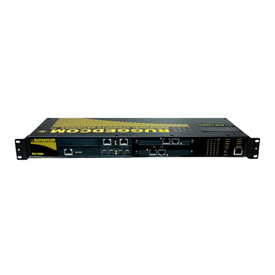
RUGGEDCOM RX1000 Chapter 1 Installation Guide Introduction Section 1.2 Ports, Controls and Indicator LEDs The RX1000 features various ports, controls and indicator LEDs on the front panel for configuring and troubleshooting the device. Figure 1: Front Panel 1. Port Status Indicator LEDs 2. - Page 10 RUGGEDCOM RX1000 Chapter 1 Installation Guide Introduction Ports, Controls and Indicator LEDs...
-
Page 11: Installing The Device
This product contains no user-serviceable parts. Attempted service by unauthorized personnel shall render all warranties null and void. Changes or modifications not expressly approved by Siemens Canada Ltd. could invalidate specifications, test results, and agency approvals, and void the user's authority to operate the equipment. -
Page 12: Mounting The Device To A Rack
Chapter 2 RUGGEDCOM RX1000 Installing the Device Installation Guide NOTE For detailed dimensions of the device with either rack, DIN rail or panel hardware installed, refer to Chapter 5, Dimension Drawings. The following sections describe the various methods of mounting the device: •... -
Page 13: Mounting The Device On A Din Rail
RUGGEDCOM RX1000 Chapter 2 Installation Guide Installing the Device Section 2.1.2 Mounting the Device on a DIN Rail For DIN rail installations, the RX1000 can be equipped with panel/DIN rail adapters pre-installed on each side of the chassis. The adapters allow the device to be slid onto a standard 35 mm (1.4 in) DIN rail. -
Page 14: Connecting Power
Chapter 2 RUGGEDCOM RX1000 Installing the Device Installation Guide Figure 4: Panel Mounting 1. Screw 2. Panel/DIN Rail Adaptor Install the supplied screws to secure the adapters to the panel. Section 2.2 Connecting Power The RX1000 supports single or dual redundant AC and/or DC power supplies. The use of two power modules is recommended to provide redundancy and load balancing. -
Page 15: Connecting Ac Power
RUGGEDCOM RX1000 Chapter 2 Installation Guide Installing the Device • It is recommended to provide a separate circuit breaker for each power supply module. • Equipment must be installed according to applicable local wiring codes and standards. The following sections describe how to connect power to the device: •... -
Page 16: Connecting Dc Power
Chapter 2 RUGGEDCOM RX1000 Installing the Device Installation Guide Figure 5: Terminal Block Wiring 1. Screw-Type Terminal Block 2. Pluggable Terminal Block 3. Jumper 4. Positive/Live (+/L) Terminal 5. Negative/Neutral (-/N) Terminal 6. Surge Ground Terminal 7. Chassis Ground Terminal Connect the negative wire from the power source to the negative/neutral (-/N) terminal on the terminal block. - Page 17 RUGGEDCOM RX1000 Chapter 2 Installation Guide Installing the Device NOTE The screw-type terminal block is installed using Philips screws and compression plates, allowing either bare wire connections or crimped terminal lugs. Use #6 size ring lugs for secure, reliable screws, which must be removed to make connections.
-
Page 18: Wiring Examples
Chapter 2 RUGGEDCOM RX1000 Installing the Device Installation Guide Section 2.2.3 Wiring Examples The following illustrate how to connect power to single and dual power supplies. Figure 7: Single AC Power Supply Figure 8: Single DC Power Supply Wiring Examples... - Page 19 RUGGEDCOM RX1000 Chapter 2 Installation Guide Installing the Device Figure 9: Dual AC Power Supply Figure 10: Dual DC Power Supply Wiring Examples...
-
Page 20: Connecting The Failsafe Alarm Relay
Chapter 2 RUGGEDCOM RX1000 Installing the Device Installation Guide Figure 11: Dual AC/DC Power Supply Section 2.3 Connecting the Failsafe Alarm Relay The failsafe relay can be configured to latch based on alarm conditions. The NO (Normally Open) contact is closed when the unit is powered and there are no active alarms. -
Page 21: Grounding The Device
Section 2.5 Cabling Recommendations Siemens does not recommend the use of copper cabling of any length for critical, real-time substation automation applications. All copper Ethernet ports on RUGGEDCOM products include transient suppression circuitry to protect against damage from electrical transients and conform with IEC 61850-3 and IEEE 1613 Class 1 standards. -
Page 22: Connecting To The Device
Installing the Device Installation Guide Siemens also does not recommend using copper Ethernet ports to interface with devices in the field across distances that could produce high levels of ground potential rise (i.e. greater than 2500 V), during line-to-ground fault conditions. -
Page 23: Communication Ports
RUGGEDCOM RX1000 Chapter 3 Installation Guide Communication Ports Communication Ports The RX1000 can be equipped with various types of communication ports to enhance its abilities and performance. To determine which ports are equipped on the device, refer to the factory data file available through ROX . -
Page 24: Copper Ethernet Ports
Chapter 3 RUGGEDCOM RX1000 Communication Ports Installation Guide • Section 3.4, “DDS Ports” • Section 3.5, “Modem Port” • Section 3.6, “Serial Ports” • Section 3.7, “Precision Time Protocol (PTP) Ports” • Section 3.8, “RS232 External Modem Ports” • Section 3.9, “Cellular Modems”... -
Page 25: Wan Ports
RUGGEDCOM RX1000 Chapter 3 Installation Guide Communication Ports Section 3.2 WAN Ports The RX1000 can optionally be equipped with T1/E1 WAN ports, which communicate on standard telephony communication lines. T1/E1 WAN ports are equipped with standard RJ45 receptacles. The following is the pin-out for the T1/E1 ports:... -
Page 26: Dds Ports
Chapter 3 RUGGEDCOM RX1000 Communication Ports Installation Guide Section 3.4 DDS Ports The RX1000 can optionally be equipped with a 56/64 kbps DDS (Data Distribution Service) card that uses standard RJ45 receptacles. The following is the pin-out for the DDS ports:... -
Page 27: Serial Ports
RUGGEDCOM RX1000 Chapter 3 Installation Guide Communication Ports NOTE This product meets the applicable Industry Canada technical specifications. The Ringer Equivalence Number is an indication of the maximum number of devices allowed to be connected to a telephone interface. The termination on an interface may consist of any combination of devices subject only to the requirement that the sum of the RENs of all the devices does not exceed five. -
Page 28: Precision Time Protocol (Ptp) Ports
Chapter 3 RUGGEDCOM RX1000 Communication Ports Installation Guide Name Description TxCLK Transmit Clock RxCLK Receive Clock Data Terminal Ready RS232 Mode RS485 Mode RS422 Mode DSR/RI Common (Isolated) Ground Figure 22: Serial RJ45 Port Pin Configuration TX/RX+ TX/RX- Shield Chassis Ground Connected internally. -
Page 29: Irig-B Outputs
RUGGEDCOM RX1000 Chapter 3 Installation Guide Communication Ports Figure 23: PTP Card 1. IEEE 1588 Ethernet Interface 2. GPS Antenna Input 3. IRIG-B AM Output 4. IRIG-B PWM (TTL) or PPS Output 1 5. IRIG-B PWM (TTL) or PPS Output 2 NTP is the standard for synchronizing the clocks of computer systems throughout the Internet and is suitable for systems that require accuracies in the order of 1 ms. -
Page 30: Pulse-Per-Second (Pps) Output
Chapter 3 RUGGEDCOM RX1000 Communication Ports Installation Guide Figure 24: IRIG-B Simplified Schematic 1. Source 2. Cabling 3. Device The maximum number of devices (N) that can be connected to the source is determined by checking if the source current (IS) required to drive the connected devices is less than the maximum drive current the source can provide, and verifying that the load voltage (VL) the connected devices see is greater than the minimum required voltage. -
Page 31: Gps Antenna
The time delay is dependent on the type of dielectric material in the cable and ranges from 1 to 2 ns/ft. Siemens provides a method to account for this delay through the web management interface by entering the time delay into the cable compensation box under PTP General Configuration. -
Page 32: Lightning Considerations
Siemens also recommends installing lightning arrestors in the antenna line to protect the receiver and connected devices. If a lightning arrestor is installed it is important to ensure that it has a low impedance path to ground. -
Page 33: Cellular Modems
RUGGEDCOM RX1000 Chapter 3 Installation Guide Communication Ports Name Description Carrier Detect Receive data Transmit Data Data Terminal Ready Common Ground Data Set Ready Request To Send Figure 25: Serial DB9 Port Pin Configuration Clear To Send RI (No Ring Indicator... -
Page 34: Hspa (Gsm) Cellular Modem
Chapter 3 RUGGEDCOM RX1000 Communication Ports Installation Guide Figure 26: EVDO Cellular Modem The EVDO cellular modem has the following minimum requirements: Frequency Range (MHz) Maximum RX Diversity Band VSWR Allowable Support Gain (dBi) Cell 824-849 869-894 <2:1 <2:1 4.95... -
Page 35: Gsm/Edge Internal Cellular Modem
RUGGEDCOM RX1000 Chapter 3 Installation Guide Communication Ports Supported Frequency Bands WARNING! Electromagnet radiation hazard – risk of serious injury. Do not exceed the maximum antenna gain. Aside from causing cellular interference for other devices that use the same band, adverse health effects for individuals in the area may occur. -
Page 36: Connecting Multiple Rs485 Devices
Chapter 3 RUGGEDCOM RX1000 Communication Ports Installation Guide Insert the SIM card with the angled side first. An audible click will indicate the SIM card is in position. Install the access panel. Connect power to the device. Supported Frequency Bands WARNING! Electromagnet radiation hazard –... - Page 37 RUGGEDCOM RX1000 Chapter 3 Installation Guide Communication Ports 120Ω 10nF 120Ω 10nF Figure 29: Recommended RS485 Wiring 1. RX1000 Device 2. Common (Isolated Ground) 3. Negative 4. Positive 5. Shield to Earth (Connected At a Single Point) 6. RS485 Devices (32 Total)
- Page 38 RUGGEDCOM RX1000 Chapter 3 Installation Guide Communication Ports Connecting Multiple RS485 Devices...
-
Page 39: Technical Specifications
RUGGEDCOM RX1000 Chapter 4 Installation Guide Technical Specifications Technical Specifications The following sections provide important technical specifications related to the device and available modules: • Section 4.1, “Power Supply Specifications” • Section 4.2, “Failsafe Relay Specifications” • Section 4.3, “Copper Ethernet Port Specifications”... -
Page 40: Copper Ethernet Port Specifications
Chapter 4 RUGGEDCOM RX1000 Technical Specifications Installation Guide Section 4.3 Copper Ethernet Port Specifications The following details the specifications for copper Ethernet ports that can be ordered with the RX1000. Wiring Maximum Speed Connector Duplex Cable Type Isolation Standard Distance... -
Page 41: Mechanical Specifications
RUGGEDCOM RX1000 Chapter 4 Installation Guide Technical Specifications Section 4.7 Mechanical Specifications Parameter Value Dimensions Refer to Chapter 5, Dimension Drawings Weight 10 lb (4.5 Kg) Ingress Protection IP40 Enclosure 18 AWG galvanized steel Mechanical Specifications... - Page 42 RUGGEDCOM RX1000 Chapter 4 Installation Guide Technical Specifications Mechanical Specifications...
-
Page 43: Dimension Drawings
RUGGEDCOM RX1000 Chapter 5 Installation Guide Dimension Drawings Dimension Drawings NOTE All dimensions are in millimeters, unless otherwise stated. 437.4 44.5 Figure 30: Overall Dimensions... - Page 44 Chapter 5 RUGGEDCOM RX1000 Dimension Drawings Installation Guide 479.3 461.0 21.1 32.5 Figure 31: Rack Mount Dimensions...
- Page 45 RUGGEDCOM RX1000 Chapter 5 Installation Guide Dimension Drawings 486.4 476.3 438.2 Figure 32: Panel and DIN Rail Mount Dimensions...
- Page 46 RUGGEDCOM RX1000 Chapter 5 Installation Guide Dimension Drawings...
-
Page 47: Certification
RUGGEDCOM RX1000 Chapter 6 Installation Guide Certification Certification The RX1000 device has been thoroughly tested to guarantee its conformance with recognized standards and has received approval from recognized regulatory agencies. • Section 6.1, “Agency Approvals” • Section 6.2, “FCC Compliance”... -
Page 48: Emi And Environmental Type Tests
Chapter 6 RUGGEDCOM RX1000 Certification Installation Guide Section 6.4 EMI and Environmental Type Tests The RX1000 has passed the following EMI and environmental tests. IEC 61850-3 EMI Type Tests NOTE • In the case of an all fiber port configuration, this product meets all Class 2 requirements. Otherwise, all Class 1 requirements are met for copper ports. - Page 49 RUGGEDCOM RX1000 Chapter 6 Installation Guide Certification Test Description Test Levels Severity Levels IEC 61000-4-12 Damped Oscillatory Signal ports 2.5 kV common, 1 kV differential mode @ 1 MHz DC Power ports 2.5kV common,1kV differential mode @ 1 MHz AC Power ports 2.5 kV common,...
-
Page 50: Cellular Modem Certifications
Chapter 6 RUGGEDCOM RX1000 Certification Installation Guide Test Description Test Levels AC Power ports 2.5 kV common and differential mode @ 1 MHz IEEE C37.90 HV Impulse Signal ports 5 kV (Failsafe Relay) DC Power ports 5 kV AC Power ports 5 kV IEEE C37.90...
Need help?
Do you have a question about the RUGGEDCOM RX1000 and is the answer not in the manual?
Questions and answers