Siemens RUGGEDCOM RS900G Installation Manual
Hide thumbs
Also See for RUGGEDCOM RS900G:
- Installation manual (36 pages) ,
- Installation manual (44 pages)
Table of Contents
Advertisement
Quick Links
Download this manual
See also:
Installation Manual
Advertisement
Table of Contents

Subscribe to Our Youtube Channel
Related Manuals for Siemens RUGGEDCOM RS900G


Summary of Contents for Siemens RUGGEDCOM RS900G
- Page 1 Preface Introduction Installing the Device RUGGEDCOM RS900G Communication Ports Technical Specifications Dimension Drawings Installation Guide Certification 6/2014 RC1025-EN-02...
-
Page 2: Security Information
Warranty Siemens warrants this product for a period of five (5) years from the date of purchase, conditional upon the return to factory for maintenance during the warranty term. This product contains no user-serviceable parts. Attempted service by unauthorized personnel shall render all warranties null and void. -
Page 3: Table Of Contents
RUGGEDCOM RS900G Installation Guide Table of Contents Table of Contents Preface ........................ Alerts ..............................v Related Documents ..........................v Accessing Documentation ........................v Training .............................. vi Customer Support ..........................vi Chapter 1 Introduction ......................1.1 Feature Highlights ........................1 1.2 Ports, Controls and Indicator LEDs ....................2 Chapter 2 Installing the Device .................... - Page 4 RUGGEDCOM RS900G Table of Contents Installation Guide 4.4 Operating Environment ....................... 18 4.5 Mechanical Specifications ......................19 Chapter 5 Dimension Drawings ..................Chapter 6 Certification ......................6.1 Agency Approvals ........................23 6.2 FCC Compliance ........................23 6.3 Industry Canada Compliance ...................... 24...
-
Page 5: Preface
Installation Guide Preface Preface This guide describes the RUGGEDCOM RS900G. It describes the major features of the device, installation, commissioning and important technical specifications. It is intended for use by network technical support personnel who are responsible for the installation, commissioning and maintenance of the device. -
Page 6: Training
Siemens sales representative. Customer Support Customer support is available 24 hours, 7 days a week for all Siemens customers. For technical support or general information, please contact Siemens Customer Support through any of the following methods: • Online Visit http://www.siemens.com/automation/support-request... -
Page 7: Introduction
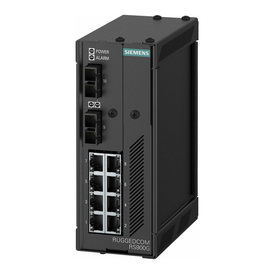
Introduction Introduction The RUGGEDCOM RS900G is an industrially hardened, fully managed Ethernet switch providing dual fiber optical Gigabit Ethernet ports and eight Fast Ethernet copper ports. Designed to operate reliably in harsh industrial environments, the RS900G provides a high level of immunity to electromagnetic interference and heavy electrical surges typical of environments found in electric utility substations, factory floors or in curb side traffic control cabinets. -
Page 8: Ports, Controls And Indicator Leds
Chapter 1 RUGGEDCOM RS900G Introduction Installation Guide • Universal high-voltage range: 88-300 VDC or 85-264 VAC • Dual low-voltage DC inputs (12, 24 or 48 VDC) • CSA/UL 60950-1 safety approved to 85 °C (185 °F) Simple Plug and Play Operation •... - Page 9 RUGGEDCOM RS900G Chapter 1 Installation Guide Introduction Alarm Indicator LED The alarm indicator LED illuminates when an alarm condition exists. RS232 Serial Console Port This port is for interfacing directly with the device and accessing initial management functions. Ports, Controls and Indicator LEDs...
- Page 10 RUGGEDCOM RS900G Chapter 1 Installation Guide Introduction Ports, Controls and Indicator LEDs...
-
Page 11: Installing The Device
RUGGEDCOM RS900G Chapter 2 Installation Guide Installing the Device Installing the Device The following sections describe how to install the device, including mounting the device, installing/removing modules, connecting power, and connecting the device to the network. DANGER! Electrocution hazard – risk of serious personal injury and/or damage to equipment. Before performing any maintenance tasks, make sure all power to the device has been disconnected and wait approximately two minutes for any remaining energy to dissipate. -
Page 12: Mounting The Device On A Din Rail
Chapter 2 RUGGEDCOM RS900G Installing the Device Installation Guide Section 2.1.1 Mounting the Device on a DIN Rail For DIN rail installations, the RS900G can be equipped with a DIN rail bracket pre-installed on the back of the chassis. The bracket allows the device to be slid onto a standard 35 mm (1.4 in) DIN rail. -
Page 13: Connecting Power
Ground. Note that all line-to-ground transient protection circuitry will be disabled. IMPORTANT! Siemens requires the use of external surge protection in VDSL applications where the line may be subject to surges greater than that for which the device is rated. Use the following specifications as a guide for VDSL external surge protection: •... -
Page 14: Connecting High Ac/Dc Power
Chapter 2 RUGGEDCOM RS900G Installing the Device Installation Guide • Insertion Loss: < 0.1 dB at 10 MHz • Peak Surge Current: 10 kA, 8x20µs waveform IMPORTANT! Use only #16 gage copper wiring when connecting terminal blocks. The following sections describe how to connect power to the device: •... -
Page 15: Connecting Low Dc Power
RUGGEDCOM RS900G Chapter 2 Installation Guide Installing the Device Figure 4: Terminal Block Wiring 1. Positive/Live (+/L) Terminal 2. Negative/Neutral (-/N) Terminal 3. Surge Ground Terminal 4. Braided Ground Cable Connect the negative wire from the power source to the negative/neutral (-/N) terminal on the terminal block. - Page 16 Chapter 2 RUGGEDCOM RS900G Installing the Device Installation Guide Figure 5: Terminal Block Wiring - Single DC Power Supply Inputs 1. Positive Terminal 2. Negative Terminal 3. Surge Ground Terminal 4. Braided Ground Cable Figure 6: Terminal Block Wiring - Dual DC Power Supply Inputs 1.
-
Page 17: Connecting The Failsafe Alarm Relay
RUGGEDCOM RS900G Chapter 2 Installation Guide Installing the Device Connect the negative wire from the power source to the negative terminal on the terminal block. Using a braided wire or other appropriate grounding wire, connect the surge ground terminal to the chassis ground connection. -
Page 18: Cabling Recommendations
Section 2.5 Cabling Recommendations Siemens does not recommend the use of copper cabling of any length for critical, real-time substation automation applications. All copper Ethernet ports on RUGGEDCOM products include transient suppression circuitry to protect against damage from electrical transients and conform with IEC 61850-3 and IEEE 1613 Class 1 standards. -
Page 19: Communication Ports
RUGGEDCOM RS900G Chapter 3 Installation Guide Communication Ports Communication Ports The RS900G can be equipped with various types of communication ports to enhance its abilities and performance. To determine which ports are equipped on the device, refer to the factory data file available through ROS. -
Page 20: Sfp Optic Ethernet Ports
To install an SFP optical port, do the following: CAUTION! Electrical hazard – risk of damage to equipment. Use only components certified by Siemens with RUGGEDCOM products. Damage to the module and device may occur if compatibility and reliability have not been properly assessed. -
Page 21: Removing An Sfp Optical Port
RUGGEDCOM RS900G Chapter 3 Installation Guide Communication Ports CAUTION! Electrical hazard – risk of damage to equipment. Make sure all electrostatic energy is dissipated before installing or removing components from the device. An electrostatic discharge (ESD) can cause serious damage to the component once it is outside the chassis. - Page 22 Chapter 3 RUGGEDCOM RS900G Communication Ports Installation Guide Figure 14: Removing an SFP Optical Port (Typical) 1. SFP Optical Port 2. Metal Bail-Latch Store the port in an ESD-safe bag or other suitable ESD-safe environment, free from moisture and stored at the proper temperature (-40 to 85 °C or -40 to 185 °F).
-
Page 23: Technical Specifications
RUGGEDCOM RS900G Chapter 4 Installation Guide Technical Specifications Technical Specifications The following sections provide important technical specifications related to the device and available modules: • Section 4.1, “Power Supply Specifications” • Section 4.2, “Failsafe Relay Specifications” • Section 4.3, “Fiber Optic Ethernet Port Specifications”... -
Page 24: Fiber Optic Ethernet Port Specifications
NOTE • Maximum segment length is greatly dependent on factors such as fiber quality, and the number of patches and splices. Consult a Siemens Sales associate when determining maximum segment distances. • All optical power numbers are listed as dBm averages. To convert from average to peak add 3 dBm. -
Page 25: Mechanical Specifications
RUGGEDCOM RS900G Chapter 4 Installation Guide Technical Specifications Parameter Range Comments Operating Altitude 0 to 15240 m Over temperature range of -40 to 85 °C (-40 to 185 °F) (0 to 50000 ft) Section 4.5 Mechanical Specifications Parameter Value Dimensions... - Page 26 RUGGEDCOM RS900G Chapter 4 Installation Guide Technical Specifications Mechanical Specifications...
-
Page 27: Dimension Drawings
RUGGEDCOM RS900G Chapter 5 Installation Guide Dimension Drawings Dimension Drawings NOTE All dimensions are in millimeters, unless otherwise stated. 65.126 116.586 2.540 Figure 15: Overall Dimensions... - Page 28 Chapter 5 RUGGEDCOM RS900G Dimension Drawings Installation Guide 13.639 101.600 11.176 78.740 120.650 Figure 16: Panel and DIN Rail Mount Dimensions...
-
Page 29: Certification
RUGGEDCOM RS900G Chapter 6 Installation Guide Certification Certification The RS900G device has been thoroughly tested to guarantee its conformance with recognized standards and has received approval from recognized regulatory agencies. • Section 6.1, “Agency Approvals” • Section 6.2, “FCC Compliance”... -
Page 30: Industry Canada Compliance
Chapter 6 RUGGEDCOM RS900G Certification Installation Guide Section 6.3 Industry Canada Compliance CAN ICES-3 (A) / NMB-3 (A) Section 6.4 EMI and Environmental Type Tests The RS900G has passed the following EMI and environmental tests. IEC 61850-3 Type Tests Test... - Page 31 RUGGEDCOM RS900G Chapter 6 Installation Guide Certification Test Description Test Levels Severity Levels DC Power ports 2.5 kV common, 1 kV differential mode @ 1 MHz AC Power ports 2.5 kV common, 1 kV differential mode @ 1 MHz IEC 61000-4-16...
-
Page 32: Environmental Type Tests
Chapter 6 RUGGEDCOM RS900G Certification Installation Guide IEEE 1613 IEEE Test Description Test Levels Clause AC Power ports 2 kVAC Environmental Type Tests Test Description Test Levels Severity Levels IEC 60068-2-1 Cold Temperature Test Ad -40 °C (-40 °F), 16 Hours...
Need help?
Do you have a question about the RUGGEDCOM RS900G and is the answer not in the manual?
Questions and answers