Siemens RUGGEDCOM RX1501 Installation Manual
Hide thumbs
Also See for RUGGEDCOM RX1501:
- Installation manual (68 pages) ,
- User manual (856 pages) ,
- Reference manual (252 pages)

Related Manuals for Siemens RUGGEDCOM RX1501


Summary of Contents for Siemens RUGGEDCOM RX1501
- Page 1 Preface Introduction Installing the Device RUGGEDCOM RX1501 Communication Ports Technical Specifications Dimension Drawings Installation Guide Certification 11/2014 RC1054-EN-03...
-
Page 2: Security Information
Warranty Siemens warrants this product for a period of five (5) years from the date of purchase, conditional upon the return to factory for maintenance during the warranty term. This product contains no user-serviceable parts. Attempted service by unauthorized personnel shall render all warranties null and void. -
Page 3: Table Of Contents
RUGGEDCOM RX1501 Installation Guide Table of Contents Table of Contents Preface ........................ Alerts ..............................v Related Documents ..........................v Accessing Documentation ........................v Training .............................. vi Customer Support ..........................vi Chapter 1 Introduction ......................1.1 Feature Highlights ........................1 1.2 Ports, Controls and Indicator LEDs ....................3 Chapter 2 Installing the Device .................... - Page 4 RUGGEDCOM RX1501 Table of Contents Installation Guide 3.3 SFP Optic Ethernet Ports ......................21 3.3.1 Installing an SFP Optical Port ..................21 3.3.2 Removing an SFP Optical Port ..................22 3.4 WAN Modules ..........................23 3.5 Serial Ports ..........................24 3.6 Cellular Modem Modules ......................
-
Page 5: Preface
Installation Guide Preface Preface This guide describes the RUGGEDCOM RX1501. It describes the major features of the device, installation, commissioning and important technical specifications. It is intended for use by network technical support personnel who are responsible for the installation, commissioning and maintenance of the device. -
Page 6: Training
Siemens sales representative. Customer Support Customer support is available 24 hours, 7 days a week for all Siemens customers. For technical support or general information, contact Siemens Customer Support through any of the following methods: • Online Visit http://www.siemens.com/automation/support-request... -
Page 7: Introduction
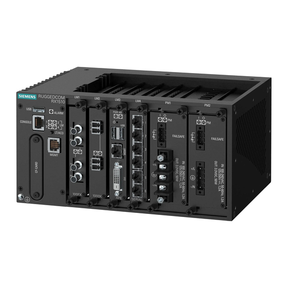
Introduction Introduction The RUGGEDCOM RX1501 is a cost-efficient, rugged Layer 3 switch and router. The RX1501’s modular and field replaceable platform can be equipped with WAN, serial, and Ethernet options, making it ideally suited for electric power utilities, the industrial plant floor, and traffic control systems. - Page 8 Chapter 1 RUGGEDCOM RX1501 Introduction Installation Guide • Up to 8 ports Gigabit Ethernet WAN Port Options • T1/E1 (channelized) • E1 75 Ω via BNC • Cellular (HSPA/EVDO) • DDS Serial Ports • Fully compliant EIA/TIA RS485, RS422 and RS232 serial ports (software selectable) with RJ45 connectors, DNP and MODBUS •...
-
Page 9: Ports, Controls And Indicator Leds
RUGGEDCOM RX1501 Chapter 1 Installation Guide Introduction • Input voltage ranges: 13-36 VDC and 37-72 VDC or 85-264 VAC and 88-300 VDC for worldwide operability • CSA/UL 60950-1 safety approved to 85 °C (185 °F) Section 1.2 Ports, Controls and Indicator LEDs The RX1501 features various ports, controls and indicator LEDs on the front panel for configuring and troubleshooting the device. - Page 10 CAUTION! Configuration hazard – risk of data corruption/loss. Do not open the compact flash card port, unless specifically instructed to by a Siemens Customer Support representative. The warranty will be void otherwise. Removing the compact flash card improperly can corrupt configuration data.
-
Page 11: Installing The Device
This product contains no user-serviceable parts. Attempted service by unauthorized personnel shall render all warranties null and void. Changes or modifications not expressly approved by Siemens Canada Ltd. could invalidate specifications, test results, and agency approvals, and void the user's authority to operate the equipment. -
Page 12: Mounting The Device To A Rack
Chapter 2 RUGGEDCOM RX1501 Installing the Device Installation Guide NOTE For detailed dimensions of the device with either rack, DIN rail or panel hardware installed, refer to Chapter 5, Dimension Drawings. The following sections describe the various methods of mounting the device: •... -
Page 13: Mounting The Device On A Din Rail
RUGGEDCOM RX1501 Chapter 2 Installation Guide Installing the Device NOTE The chassis features multiple mounting holes, allowing the rack mount adapters to be installed up to 25 mm (1 in) from the face of the device. Figure 2: Rack Mount Adapters 1. -
Page 14: Mounting The Device To A Panel
Chapter 2 RUGGEDCOM RX1501 Installing the Device Installation Guide Install one of the supplied screws on either side of the device to secure the adapters to the DIN rails. Section 2.1.3 Mounting the Device to a Panel For panel installations, the RX1501 can be equipped with panel/DIN rail adapters pre-installed on each side of the chassis. -
Page 15: Installing/Removing Power Supplies
RUGGEDCOM RX1501 Chapter 2 Installation Guide Installing the Device DANGER! Electrocution hazard – risk of serious personal injury or death. Make sure the power source is off before servicing the power supply terminal. IMPORTANT! • Use only #16 gage copper wiring when connecting terminal blocks. -
Page 16: Removing A Power Supply
Chapter 2 RUGGEDCOM RX1501 Installing the Device Installation Guide Remove the blank power module assembly or, if equipped, the currently installed power supply. For information about removing a power supply, refer to Section 2.2.1.2, “Removing a Power Supply”. Insert the power supply into the empty slot. When power is supplied to the device, the top and bottom LEDs on the power supply should be green, indicating that power is being received and supplied to the device. -
Page 17: Connecting High Ac/Dc Power
RUGGEDCOM RX1501 Chapter 2 Installation Guide Installing the Device Section 2.2.2 Connecting High AC/DC Power To connect a high AC/DC power supply to the device, do the following: DANGER! Electrocution hazard – risk of death, serious personal injury and/or damage to the device. Make sure the supplied cover is always installed over high voltage screw-type terminal blocks. -
Page 18: Connecting Low Dcpower
Chapter 2 RUGGEDCOM RX1501 Installing the Device Installation Guide Section 2.2.3 Connecting Low DC Power To connect a low DC power supply to the device, do the following: CAUTION! Electrical hazard – risk of damage to equipment. Do not connect AC power cables to a 12, 24 or 48 VDC power supply terminal block. -
Page 19: Connecting The Failsafe Alarm Relay
RUGGEDCOM RX1501 Chapter 2 Installation Guide Installing the Device Section 2.3 Connecting the Failsafe Alarm Relay The failsafe relay can be configured to latch based on alarm conditions. The NO (Normally Open) contact is closed when the unit is powered and there are no active alarms. If the device is not powered or if an active alarm is configured, the relay opens the NO contact and closes the NC (Normally Closed) contact. -
Page 20: Connecting To The Device
Chapter 2 RUGGEDCOM RX1501 Installing the Device Installation Guide Section 2.5 Connecting to the Device The following describes the various methods for accessing the ROX II console and Web interfaces on the device. For more detailed instructions, refer to the ROX II User Guide for the RX1501. -
Page 21: Cabling Recommendations
Section 2.6.1 Protection On Twisted-Pair Data Ports Siemens does not recommend the use of copper cabling of any length for critical, real-time substation automation applications. All copper Ethernet ports on RUGGEDCOM products include transient suppression circuitry to protect against damage from electrical transients and conform with IEC 61850-3 and IEEE 1613 Class 1 standards. - Page 22 Chapter 2 RUGGEDCOM RX1501 Installing the Device Installation Guide Follow these recommendations for copper data cabling in high electrical noise environments: • Data cable lengths should be as short as possible, preferably 3 m (10 ft) in length. Copper data cables should not be used for inter-building communications.
-
Page 23: Communication Ports
RUGGEDCOM RX1501 Chapter 3 Installation Guide Communication Ports Communication Ports The RX1501 can be equipped with various types of communication ports to enhance its abilities and performance. Each set of communication ports is part of a field replaceable module that makes switching ports fast and easy. -
Page 24: Copper Ethernet Ports
Chapter 3 RUGGEDCOM RX1501 Communication Ports Installation Guide Section 3.1 Copper Ethernet Ports The RX1501 supports several 10/100Base-TX Ethernet ports with RJ45 or M12 (bypass or non-bypass) connectors. The RJ45 and M12 connectors are directly connected to the chassis ground on the device and can accept CAT-5 shielded twisted-pair (STP) cables. - Page 25 RUGGEDCOM RX1501 Chapter 3 Installation Guide Communication Ports Figure 23: 4 x 4-Pin 10/100TX M12 D-Coded Ports Figure 24: 4 x 4-Pin 10/100TX with M12 D-Coded Bypass and Non-Bypass Ports Each port features an LED that indicates the state of the port.
-
Page 26: Fiber Optic Ethernet Ports
Chapter 3 RUGGEDCOM RX1501 Communication Ports Installation Guide 10/100/1000Base- 10/100Base-Tx Signal Tx Signal 10/100/1000Base-Tx Signal Figure 27: 8-Pin M12 X-Coded Ethernet Port Pin Configuration 10/100Base-Tx Signal Figure 28: 4-Pin M12 D-Coded Ethernet Port Pin Configuration Terminated at GND (Ground) For specifications on the available copper Ethernet ports, refer to Section 4.4, “Copper Ethernet Port... -
Page 27: Sfp Optic Ethernet Ports
To install an SFP optical port, do the following: CAUTION! Electrical hazard – risk of damage to equipment. Use only components certified by Siemens with RUGGEDCOM products. Damage to the module and device may occur if compatibility and reliability have not been properly assessed. -
Page 28: Removing An Sfp Optical Port
Chapter 3 RUGGEDCOM RX1501 Communication Ports Installation Guide CAUTION! Electrical hazard – risk of damage to equipment. Make sure all electrostatic energy is dissipated before installing or removing components from the device. An electrostatic discharge (ESD) can cause serious damage to the component once it is outside the chassis. -
Page 29: Wan Modules
RUGGEDCOM RX1501 Chapter 3 Installation Guide Communication Ports Figure 35: Removing an SFP Optical Port (Typical) 1. SFP Optical Port 2. Metal Bail-Latch Store the port in an ESD-safe bag or other suitable ESD-safe environment, free from moisture and stored at the proper temperature (-40 to 85 °C or -40 to 185 °F). -
Page 30: Serial Ports
Chapter 3 RUGGEDCOM RX1501 Communication Ports Installation Guide Figure 38: 2 × T1/E1 with RJ45 Ports (TC2) Figure 39: 2 × E1 with BNC Ports (E02) The following is the pin-out for the BNC and RJ45 connectors: Figure 40: RJ45 T1/E1 Pin Configuration 1. -
Page 31: Cellular Modem Modules
RUGGEDCOM RX1501 Chapter 3 Installation Guide Communication Ports State Description Green Activity detected No activity For specifications on serial ports, refer to Section 4.3, “Copper Serial Port Specifications”. For information about how to connect devices configured to run in RS485 mode, refer to Section 3.10,... - Page 32 While cellular disruptions are uncommon when using a Siemens cellular modem, avoid using the cellular modem in applications where a communication failure could result in damage to equipment or personal injury to persons in the area. Siemens accepts no responsibility for any damages that may result due to wireless disruptions.
-
Page 33: Cellular Modem Installation Requirements
RUGGEDCOM RX1501 Chapter 3 Installation Guide Communication Ports Order Code Description 2 Port Cell Modem GSM,EDGE,HSPA+ 2 Port Cell Modem EVDO Rev.A Verizon Wireless 1 Port Cell Modem GSM,EDGE,HSPA+, 1 Port Cell Modem EVDO Rev.A Verizon Wireless Figure 44: W12, W22 and W32 Cellular Modems 1. -
Page 34: Diversity Requirements
Chapter 3 RUGGEDCOM RX1501 Communication Ports Installation Guide If the application does not meet these requirements, further certification is required. Section 3.6.2 Diversity Requirements Diversity, where two antennas exist within the same physical housing, is a method for improving radio signal strength. -
Page 35: Installing Sim Cards For Gsm, Edge And Hspa+ Cellular Modems
RUGGEDCOM RX1501 Chapter 3 Installation Guide Communication Ports Section 3.6.4 Installing SIM Cards for GSM, EDGE and HSPA+ Cellular Modems To install a SIM card in a GSM, EDGE or HSPA+ cellular modem, do the following: CAUTION! Static electricity hazard – risk of damage to equipment. Make sure to take appropriate anti-static precautions before opening the cellular modem module. -
Page 36: Dds (Digital Data Services) Modules
Chapter 3 RUGGEDCOM RX1501 Communication Ports Installation Guide Figure 46: W12, W22, W32 Cellular Modem 1. SIM Card Cage 2 2. SIM Card Cage 1 Open SIM card cage 1 by sliding the silver catch towards the antenna connectors and flip the cage up. -
Page 37: Ruggedcom Ape Module
RUGGEDCOM RX1501 Chapter 3 Installation Guide Communication Ports The module is compatible with the following standards: • AT&T PUB 62310 (Standard DDS) • BELLCORE TA-TSY-000077 • BELLCORE TR-TSY-000458 • ANSI T1.410 It also supports the following operating modes: Operating Mode... -
Page 38: Installing/Removing Modules
Chapter 3 RUGGEDCOM RX1501 Communication Ports Installation Guide Gigabit Ethernet (GbE) ports, USB ports and a DVI-D video port. For more information about RX1501 APE, including installation and setup instructions, refer to the RUGGEDCOM APE User Guide. CAUTION! Electrical hazard – risk of power failure. Installing more APE modules than allowed can lead to power fluctuations and irregular shut downs. -
Page 39: Removing A Module
RUGGEDCOM RX1501 Chapter 3 Installation Guide Communication Ports Figure 50: Installing a Module 1. Module 2. Chassis 3. Screw Tighten the screws to secure the module. If necessary, install the device in the rack. Connect power to the device. Section 3.9.2... -
Page 40: Connecting Multiple Rs485 Devices
Chapter 3 RUGGEDCOM RX1501 Communication Ports Installation Guide Figure 51: Installing a Module 1. Module 2. Chassis 3. Screw Install a new module or a blank module (to prevent the ingress of dust and dirt). For more information, refer Section 3.9.2, “Removing a Module”. - Page 41 RUGGEDCOM RX1501 Chapter 3 Installation Guide Communication Ports 120Ω 10nF 120Ω 10nF Figure 52: Recommended RS485 Wiring 1. RX1501 Device 2. Common (Isolated Ground) 3. Negative 4. Positive 5. Shield to Earth (Connected At a Single Point) 6. RS485 Devices (32 Total)
- Page 42 RUGGEDCOM RX1501 Chapter 3 Installation Guide Communication Ports Connecting Multiple RS485 Devices...
-
Page 43: Technical Specifications
RUGGEDCOM RX1501 Chapter 4 Installation Guide Technical Specifications Technical Specifications The following sections provide important technical specifications related to the device and available modules: • Section 4.1, “Power Supply Specifications” • Section 4.2, “Failsafe Relay Specifications” • Section 4.3, “Copper Serial Port Specifications”... -
Page 44: Failsafe Relay Specifications
Chapter 4 RUGGEDCOM RX1501 Technical Specifications Installation Guide Section 4.2 Failsafe Relay Specifications Maximum Switching Voltage Rated Switching Current Isolation 30 VDC 2800 VDC for 1 minute 250 VAC 6.25 A Section 4.3 Copper Serial Port Specifications Baud Rate Connector... -
Page 45: Fiber Optic Ethernet Port Specifications
RUGGEDCOM RX1501 Chapter 4 Installation Guide Technical Specifications Auto-crossover and auto-polarity. RMS 1 minute. Section 4.5 Fiber Optic Ethernet Port Specifications The following sections detail fiber optic specifications for ports that can be equipped on the RX1501. The user determines the type of optics at the time of ordering, and can determine the ports installed on a particular unit by reading the factory data file via the ROX II user interface. -
Page 46: Gigabit Ethernet (1 Gbps) Optical Specifications
NOTE • Maximum segment length is greatly dependent on factors such as fiber quality, and the number of patches and splices. Consult a Siemens sales associate when determining maximum segment distances. • All optical power numbers are listed as dBm averages. -
Page 47: Cellular Modem Specifications
RUGGEDCOM RX1501 Chapter 4 Installation Guide Technical Specifications Power Connector Cable Tx λ (typ.) Tx min Tx max Distance Mode Sensitivity Saturation Budget Type Type (μm) (nm) (dBm) (dBm) (typ.) (km) (dBm) (dBm) (dB) 9/125 1310 SFP Gigabit Transceivers Power... -
Page 48: Operating Environment
Chapter 4 RUGGEDCOM RX1501 Technical Specifications Installation Guide Module Operating Temperature Compliance 60 to 75 °C (140 to 167 °F) Reduced Radio Frequency (RF) performance W21, W22, W32 (Second Radio) -30 to 60 °C (-22 to 140 °F) Full Radio Frequency (RF) compliance 60 to 75 °C (140 to 167 °F) -
Page 49: Mechanical Specifications
RUGGEDCOM RX1501 Chapter 4 Installation Guide Technical Specifications Section 4.9 Mechanical Specifications Parameter Value Dimensions Refer to Chapter 5, Dimension Drawings Weight Approximately 4.7 kg (10.3 lb) Ingress Protection IP40 Enclosure Aluminum Mechanical Specifications... - Page 50 RUGGEDCOM RX1501 Chapter 4 Installation Guide Technical Specifications Mechanical Specifications...
-
Page 51: Dimension Drawings
RUGGEDCOM RX1501 Chapter 5 Installation Guide Dimension Drawings Dimension Drawings NOTE All dimensions are in millimeters, unless otherwise stated. 440.9 Figure 53: Overall Dimensions... - Page 52 Chapter 5 RUGGEDCOM RX1501 Dimension Drawings Installation Guide 11.7 463.8 21.1 Figure 54: Rack Mount Dimensions 479.0 11.7 21.1 489.2 Figure 55: Panel and Din Rail Mount Dimensions...
-
Page 53: Certification
RUGGEDCOM RX1501 Chapter 6 Installation Guide Certification Certification The RX1501 device has been thoroughly tested to guarantee its conformance with recognized standards and has received approval from recognized regulatory agencies. • Section 6.1, “Agency Approvals” • Section 6.2, “FCC Compliance”... -
Page 54: Fcc Compliance
Chapter 6 RUGGEDCOM RX1501 Certification Installation Guide Agency Standards Comments Cellular LM Models RX1500PN-W11-XX RX1500PN-W12-XX RX1500PN-W32-XX FCC ID for W11 and W12: N7NMC8705 FCC ID for W32: N7NMC8705/N7N-MC5728 IC ID for W11 and W12: 2417C-MC8705 IC ID for W32: 2417C- MC8705/2417C-MC5728 Section 6.2... - Page 55 RUGGEDCOM RX1501 Chapter 6 Installation Guide Certification Severity Test Description Test Levels Levels IEC 61000-4-5 Surge Signal ports +/- 4 kV Line-to-Earth, +/- 2 kV Line-to-Line DC Power Ports +/- 2 kV Line-to-Earth, +/- 1 kV Line-to-Line AC Power Ports...
-
Page 56: Environmental Type Tests
Chapter 6 RUGGEDCOM RX1501 Certification Installation Guide Test Description Test Levels IEEE C37.90 HV Impulse Signal ports 5 kV (Failsafe Relay Output) DC Power Ports 5 kV AC Power Ports Dielectric Strength Signal ports 2 kVAC DC Power Ports 1.5 kVDC...
Need help?
Do you have a question about the RUGGEDCOM RX1501 and is the answer not in the manual?
Questions and answers