Digi WR44 Installation Manual
Hide thumbs
Also See for WR44:
- Installation manual (14 pages) ,
- Quick start manual (2 pages) ,
- User manual (948 pages)
Table of Contents
Advertisement
Quick Links
Advertisement
Table of Contents

Related Manuals for Digi WR44


Summary of Contents for Digi WR44
- Page 1 4000 Series Routers Installation Guide...
- Page 2 Digi International reserves the right to modify or revise all or part of this document, its contents, and any products described herein at any time without prior notification and shall not be responsible for any loss, cost or damage, including consequential damage, caused by reliance on these materials.
- Page 3 Any attempt to service or repair the unit by the user will void the product warranty. Products in the WR44 range are designed for indoor use only and should be used in an environment that is suitable for computers and other electronic equipment.
- Page 4 However, GSM based products contain radio devices which require specific consideration. Please take the time to read and understand the following guidance. Digi International assumes no liability for an end user‟s failure to comply with these precautions.
- Page 5 WR44 Series Installation Guide Preface This guide describes the installation procedure for the WR44 range of routers. It is intended to provide sufficient information for you to be able to connect the unit to your terminal equipment and power supply. A complete reference guide to the software features that are available on the product is available separately in PDF format which can be downloaded from the Digi International website (www.digi.com).
-
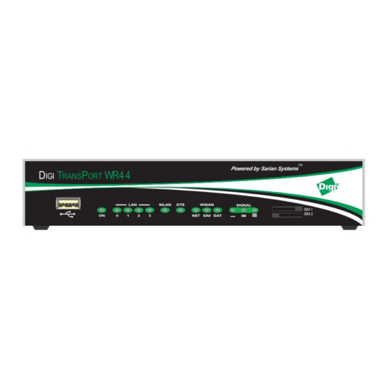
Page 6: Front Panel Features
Web interface. We recommend that you use the Web interface whenever possible. In addition to many standard LAN and Internet protocols such as PPP, the WR44 series products provide a combination of powerful but easy to use configuration, management and diagnostic tools. - Page 7 Flashes to indicate that data is being transferred over the wireless network. SIGNAL For the WR44-G, -E and -U models, the three indicators labelled SIGNAL illuminate to indicate the GSM signal strength as follows: None illuminated < -113 dBm (effectively no signal) 1 LED illuminated >= -112 dBm and <= -87 dBm (weak)
-
Page 8: Rear Panel Features
ANT. WWAN This SMA connector is used on the WR44-U model to fit the second antenna supplied with the unit. On models that do not (Aux.) support diversity antennas this connector will not be present. -
Page 9: Optional Features
Do not remove power from the unit during this operation, as corruption of the flash memory may occur. Optional features. WR44 series routers are available with a variety of hardware options. At present these are: 1 x ASY... - Page 10 WR44 Series Installation Guide Only one of the above options can be fitted and will occupy the area of the rear panel normally covered with the blanking plate. For example, if the GPS option is fitted, the rear panel will appear as shown below:...
-
Page 11: Installation
Note: You will not be able to use the router for remote communication until you have subscribed to a suitable wireless network service. WR44 series products are designed for indoor use (office or home). They should be positioned on a smooth, level surface making sure that there is adequate ventilation. Do not expose them to extremes of heat or cold, strong magnetic fields or liquids. - Page 12 SMA connector labelled ANT. WWAN (Main) on the rear panel. If you have a WR44-U, the unit will come with two WWAN antennas. When both of these are fitted the operation over the wireless network may be improved, especially in areas of low signal strength.
- Page 13 These will step you through various types of configuration. Please refer to the Digi Transport User Guide for information on the various configuration parameters. The User Guide can be downloaded from the Digi website support section.
- Page 14 This will allow you to change the configuration via the Command Line Interface (CLI). Please refer to the Digi Transport User Guide for information on how to use the CLI. The User Guide can be downloaded from the Digi website support section.
- Page 15 WR44 Series Installation Guide Programmable IO Signal Lines The auxiliary power connector has two programmable signal lines. One is an input line, the other can be configured as either an input line or an output line. The mode of operation of the input/output line is configurable through the CLI.
- Page 16 If the auxilary power connector is being used, the main power connector should NOT be used. A fused power cable (P/N 76000774) can be purchased separately from Digi International. The fuse that is supplied with the cable is a 2A, 250V quick blow fuse.
- Page 17 WR44 Series Installation Guide Input Signal Information Applied input voltage to activate: +4V to +28V DC Applied input voltage to deactivate: 0V to +1V DC (Negative voltages can be applied to -28V DC) Maximum input current: 3mA Input protection activates at more than +/-28V DC. External current limiting is needed to protect input voltages above +/-28V DC.
-
Page 18: General Specifications
WR44 Series Installation Guide General Specifications Model numbers WR44-E, WR44-U Power supply 11-58V DC, 15W Max Dimensions / Weight W211 x D136 x H39 mm, 0.9 Kg Operating temp. range 0 to +55 degrees Celsius (Commercial) -15* to +65 degrees Celsius (Industrial) - Page 19 EN61000-3-3:1995 + A1:2001 + A2:2005 EN301489-7:v1.2.1 EN301489-17:v2.1.1 following the provisions of Council Directive 2004/108/EC on radio equipment and telecommunications terminal equipment and the mutual recognition of their conformity. Name: D. Ellison Position: Director Signature: Date: August 2009 on behalf of Digi International Inc.
- Page 20 WR44 Series Installation Guide...
Need help?
Do you have a question about the WR44 and is the answer not in the manual?
Questions and answers