Table of Contents
Advertisement
Advertisement
Table of Contents

Subscribe to Our Youtube Channel
Related Manuals for Lennox CWC 090-4P


Summary of Contents for Lennox CWC 090-4P
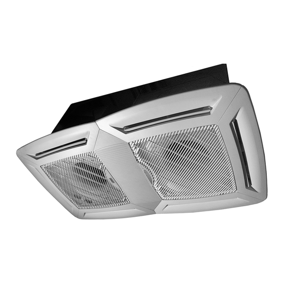
- Page 1 INSTALLATION-OPERATION & MAINTENANCE MANUAL WATER CASSETTE...
-
Page 2: Table Of Contents
Congratulations, you have made a wise choice with the purchase of your Lennox chilled water ceiling Congratulations, you have made a wise choice with the purchase of your Lennox chilled water ceiling cassette CWC/CWC-D. cassette CWC/CWC-D. This product has been designed, assembled and supplied in one of our world class manufacturing facilities This product has been designed, assembled and supplied in one of our world class manufacturing facilities and we feel sure that it will meet your expectations. -
Page 3: Product Range
CWC 090-2P CWC 070-4P CWC 070-4P 230 V - 1Ph 230 V - 1Ph 6450 6450 5800 5800 CWC 090-4P CWC 090-4P 230 V - 1Ph 230 V - 1Ph 8650 8650 7050 7050 Units 2P : 2 pipes system... -
Page 4: General Information
GENERAL INFORMATION The CEILING CASSETTES are designed to operate with chilled and hot water. They provide both cooling and dehumidification in cooling mode and heating in the latter, and filtering the air in the process. Electrical heating elements are available as an option on all units. -
Page 5: Specification
SPECIFICATIONS SPECIFICATIONS 2 PIPES SYSTEM 2 PIPES SYSTEM CWC 070-2P CWC 070-2P CWC 090-2P CWC 090-2P UNIT UNIT 6750 6750 8450 8450 W(1) W(1) Total cooling capacity Total cooling capacity W(1) W(1) 5190 5190 6600 6600 Sensible cooling capacity Sensible cooling capacity l/h(1) l/h(1) 1450... - Page 6 SPECIFICATIONS SPECIFICATIONS 4 PIPES SYSTEM 4 PIPES SYSTEM CWC 070-4P CWC 070-4P CWC 090-4P CWC 090-4P UNIT UNIT 5800 5800 7050 7050 Total cooling capacity Total cooling capacity W(1) W(1) Sensible cooling capacity Sensible cooling capacity W(1) W(1) 4350 4350...
-
Page 7: Cooling Capacities
COOLING CAPACITIES COOLING CAPACITIES CORRECTION FACTORS EXAMPLE: For the unit CWC 090-2P with chilled water rise of EXAMPLE: For the unit CWC 090-2P with chilled water rise of T = 5 T = 5 ºC, chilled water temperature 7 ºC and entering air temperature ºC, chilled water temperature 7 ºC and entering air temperature The given values have been calculated for ºC DB/19 ºC WB, according to the diagram the cooling capacity is:... -
Page 8: Heating Capacities
HEATING CAPACITY HEATING CAPACITY EXAMPLE: For the unit CWC 090-2P, with entering water temperature - entering air temperature equal to 50 ºC EXAMPLE: For the unit CWC 090-2P, with entering water temperature - entering air temperature equal to 50 ºC and water flow 1490 l/h in the diagram we get: and water flow 1490 l/h in the diagram we get: Total heating capacity = 17300 W... -
Page 9: Water Pressure Drop
CHILLED WATER AND HOT WATER CHILLED WATER CHILLED WATER CWC 070-2P / CWC 090-2P CWC 070-2P / CWC 090-2P CWC 070-4P / CWC 090-4P CWC 070-4P / CWC 090-4P CWC 070-2P / CWC 090-2P CWC 070-2P / CWC 090-2P THERMOSTAT... -
Page 10: Unit Dimensions
UNIT DIMENSIONS (mm.) Outlet hot water connection 1/2''G Outlet cool water connection 3/4''G Outlet cool water connection 3/4''G Inlet cool water connection 3/4''G 4 PIPES SYSTEM Inlet hot water 2 PIPES SYSTEM connection 1/2''G Inlet cool water Condensate pump connection 3/4''G flexible hose 10 mm I.D. -
Page 11: Drain Pipework
DRAIN PIPEWORK. CONDENSATE PUMP FLEXIBLE HOSE DRAIN TUBE CONDENSATE PUMP FLEXIBLE HOSE -The unit is fitted with a condensate pump to ensure condensate removal. -To insure that there is condensate flow, the drain tube must be installed with a fall of 2 % without obstructions, or without rising sections. - Page 12 INDOOR UNIT INSTALLATION METHOD 6.When lifting the cassette into position care should 3.Cut the false ceiling, to a maximum dimension of be taken not to lift the unit by, the drip tray, water 625x1225 mm. For a panelled ceiling removes connection, drain tube;...
-
Page 13: Control Panel
CONTROL PANEL WARNING Electric shock hazard can cause injury or death. Before attempting to perform any service or maintenance on the unit, turn OFF the electrical power, and check that the fan has stopped. ACCESS TO THE ELECTRICAL COMPONENTS OF THE UNIT Removing the corresponding plate cover screws gives access to the electrical board and terminal plate, as indicated on the drawing. -
Page 14: Instalation Of Diffuser And Inlet Grille
INSTALATION OF DIFFUSER AND INLET GRILLE MOUNTING THE DIFFUSER PANEL TO THE UNIT Check that the position in which the diffuser is mounted is the right one. 1. - Release the air intake grille. 2. - The diffuser panel can then be provisionally positioned on the cassette using the fixing clips. 3. -
Page 15: Maintenance
MAINTENANCE Fig 2. HOOKS AIR INTAKE GRILLE STAYS ELECTRICAL PANEL COVER HAND TRIGGERS ALWAYS INSTALL THE FILTER AIR FILTER If the unit operates without the filter, there is a risk of damaging the unit through dust contamination. WARNING Electric shock hazard can cause injury or death. Before attempting to perform any service or maintenance on the unit, turn OFF the electrical power, and check that the fan has stopped. - Page 16 MAINTENANCE WARNING Electric shock hazard can cause injury or death. Before attempting to perform any service or maintenance on the unit, turn OFF the electrical power, and check that the fan has stopped. ACCESS TO INTERNAL COMPONENTS When checking or replacing any internal component of the unit eg coil, fan motor, condensate pump, float switch, the drip tray and volute must be removed.
-
Page 17: Air Distribution
Air flow supplied to an adjacent room in m /h, fresh air fan at high speed. CWC 070-2P / CWC 070-4P CWC 090-2P / CWC 090-4P UNIT/MODELS Air flow m /h... -
Page 18: Fault Analysis
OPTIONS WATER CONTROL VALVE KIT (2 AND 3 WAYS, ON/OFF AND PROPORTIONAL) Water control valve NOTE THE CORRECT POSITION OF THE WATER CONTROL VALVE Water control valve (3 ways) proportional Water connection Main cable Auxiliary drip tray Auxiliary drip tray 2 PIPE SYSTEM Connecting flexible hose... -
Page 19: Points To Keep In Mind
All technical data contained in these operating instructions including the diagrams and technical description remains the property of Lennox Refac and may not be used (except for the purpose of familiarising the user with the equipment), reproduced, photocopied, transferred or transmitted to third parties without prior written authorisation from Lennox Refac. - Page 20 : + 31 33 2471 800 fax : + 31 33 2459 220 e-mail : info lennoxbenelux.com POLAND : LENNOX POLSKA SP z o.o. tél. : + 48 22 832 26 61 fax : + 48 22 832 26 62 e-mail : lennoxpolska inetia.pl PORTUGAL : LENNOX CLIMATIZAÇAO LDA.
Need help?
Do you have a question about the CWC 090-4P and is the answer not in the manual?
Questions and answers