
Related Manuals for Franke COMPACT T 400


Summary of Contents for Franke COMPACT T 400
- Page 1 T 400 Original Manual for Use and Maintenance Read the operating instructions and the chapter on safety information before operating the machine. Keep the operating instructions near the machine.
- Page 2 WEEE Disposal of the equipment by the users within the European Community ( WEEE) in compliance with the article 13 of the legislative decree is- sued on 25 July 2005, nr151 ”Implementation of the directives 2002/95/CE,2002/96/CE e 2003/108/CE, concerning the decrease in the usage of dangerous substances in the electrical and electronic equipment and the disposal of waste”.
-
Page 3: Table Of Contents
INDEX ROUTINE APPLIANCE MAINTENANCE TO GENERAL DESCRIPTION OF THE MACHINE ......... 3 BE PERFORMED By THE USER ............ 27 1.1 CONTROL PANEL DESCRIPTION ..........8 TECHNICAL DATA ................29 2. GENERAL WARNINGS ..............9 2.1 SAFETY NORMS ................9 2.2 INSTALLATION REQUIREMENTS FOR THE USER....11 2.3 WARNING/TECHNICAL DATA LABELS AND PLATES APPLIED TO THE MACHINE ....... - Page 4 11-03-2014 / LSC 178 / Rev. 00...
-
Page 5: General Description Of The Machine
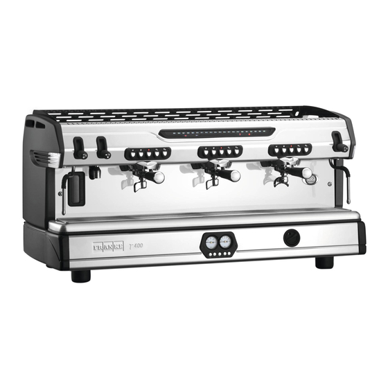
1 GENERAL DESCRIPTION OF THE MACHINE T 400 Fig. 1 LEGEND 9. Drip tray grid 17. Hot water output 1. Top cup grid 2. Steam tap 10. Water drip tray 18. One-cup filter holder 3. Hot water tap 11. Boiler pressure gauge 19. - Page 6 T 400 MAT Fig. 2 LEGEND 1. Top cup grid 9. Drip tray grid 18. One-cup filter holder 2. Steam tap 10. Water drip tray 19. Filling valve 3. Hot water tap 11. Boiler pressure gauge 20. Automatic steam delivery button for milk 4.
- Page 7 T 400 AT Fig. 3 LEGEND 1. Top cup grid 10. Water drip tray 19. Filling valve 2. Steam tap 11. Boiler pressure gauge 3. Timed hot water delivery button 12. main on/off switch 4. Touchpad 13. Adjustable foot 14. Water mains gauge 5.
- Page 8 T 400 TAKE AWAY Fig. 4 LEGEND 1. Top cup grid 10. Water drip tray 19. Filling valve 2. Steam tap 11. Boiler pressure gauge 20. grids for espresso cups 3. Hot water tap 12. main on/off switch 4. Touchpad 13.
- Page 9 COMPACT T 400 Fig. 5 LEGEND 1. Top cup grid 10. Water drip tray 2. Steam tap 11. Boiler pressure gauge 3. Hot water tap 12. main on/off switch 4. Touchpad 13. Adjustable foot 14. Water mains gauge 5. One-cup filter holder 6.
-
Page 10: Control Panel Description
1.1 CONTROL PANEL DESCRIPTION Model EK Fig. 6 LEGEND a. Technical assistance indicator (optional) f. On/OFF button for appliance electric m. 1 short coffee preset delivery button b. Indicator light for electric heating sys- heating n. 1 long coffee preset delivery button tem status g. -
Page 11: General Warnings
2. GENERAL WARNINGS read carefully the instructions and warnings contained in this manual and in the “INSTRUCTION MANUAL FOR THE INSTALLER”, since they provide important indications concerning the installation of the appliance. Attention! The electric system, water supply system, drainage system, mUST already be put in place by the customer in order to allow the proper installation of the machine. - Page 12 Danger! The electrical safety of the appliance is fully achieved only after it has been correctly connected to an earthing system as required by the laws in force. It is necessary to have the earthing connection checked by professionally qualified personnel. The manufacturer cannot be held liable for any damage caused by the lack or inefficiency of the system’s earthing connection.
-
Page 13: Installation Requirements For The User
• The appliance has IPX2 protection against water and therefore, it cannot be installed in areas where it may be subject to jets of water. • The appliance has class I protection against electric shocks. • The noise emitted by the appliance during normal operation is less than 70 dB. Attention! Failure to comply with the above regulations could jeopardise the correct operation and safety of the appliance as well as its useful lifetime. - Page 14 • Between the water mains and the water inlet pipe of the appliance, there must be a tap to stop the water flow if necessary (2 - Pict.7). • Water mains pressure must be within the range of 1 and 6 bar. If this requirement is not met, please consult the manufacturer. • The appliance is supplied without a plug. It is supposed to be directly connected to the power supply and therefore, it is necessary to fit a multi-pole power switch with a switch-contact gap of at least 3mm or more beforehand, according to the regulations in force (1 - Pict.7).
-
Page 15: Warning/Technical Data Labels And Plates Applied To The Machine
2.3 WARNING/TECHNICAL DATA LABELS AND PLATES APPLIED TO THE MACHINE In the picture below are shown the warning/technical data labels and plates placed on the machine. Warning! Dedicate the time necessary to get to know these labels. make sure that they are readable and keep them clean or replace those that have deteriorated or have become illegible (both text and graphics). -
Page 16: Removing The Packaging
3. REMOVING THE PACKAGING After unpacking the machine, please check its integrity; in case of doubt, do not use it and consult the manufacturer. Packaging materials must not be left within children’s reach since they are potentially dangerous. Attention! The appliance weight is more than 30 kg and therefore, it cannot be moved by a single person alone. Take note! Dispose of the packaging as per the norms in force of the country in which the machine is used. -
Page 17: Optional Accessories
3.2 OPTIONAL ACCESSORIES (Supplied only on request of the customer) LEGEND I. Water softener L. Water line impurity filter M. Pressure reducer N. Detergent 4. STARTING ELECTRIC AND WATER SYSTEM a) Open the water supply tap as arranged in the preparation for installation (See Pict. 7 on page 11 - Rif. 2). b) Check for any water leaks from the pipes/connections. -
Page 18: Switching On The Machine
5. SWITCHING ON THE MACHINE FILLING THE BOILER A. Open the water supply tap as arranged during the preparatory stages (see Pict. 7 on page 11 - Ref. 2). B. Verify that the water mains pressure (approx. 4 bar) is visualized on the water mains pressure gauge (14). C. -
Page 19: Coffee Preparation
D. Wait for the machine to reach the operating temperature, which can be visualized on the boiler pressure gauge (11) positioned on the appliance on Compact series machine; on 2-3-4 groups machines check on the lED light display (5) for the operating temperature (expressed in °C) pre set at the moment of the installation, to be attained. -
Page 20: Taking Hot Water For Infusions
5.2 TAKING HOT WATER FOR INFUSIONS A. Place the pitcher underneath the hot water spout. B. Open the valve (3) by moving the lever upwards until the desired amount of water is withdrawn. C. In order to stop the withdrawal close the valve by bringing back the knob or the lever to the initial position. Attention! Do not use the knob to deliver hot water before placing the pitcher below the hot water spout, to prevent possible burns. -
Page 21: Steam Delivery For Hot Drink Preparation
5.4 STEAM DELIVERY FOR HOT DRINK PREPARATION A. Insert the steam wand (8-15) into the pitcher containing the drink to be heated up. B. move the knob upward. C. At the end of the heating of the drink, shut the steam delivery by moving the knob downward. Attention! Do not turn the knob (2) to deliver steam before inserting the steam wand (8-15) into the pitcher in order to prevent possible burns. -
Page 22: Temporary Temperature Increase Function
5.6 TEMPORARY TEMPERATURE INCREASE FUNCTION (not available in the Compact line) When the machine is operated in conditions which may considerably reduce its temperature, the boiler temperature can be increased by 2°C by pressing the (i) button for approximately 2 seconds; by doing this, the programmed SET temperature keeps blinking and at the same time the temperature symbol, 2°C higher with respect to the programmed SET, starts blinking as well (e.g. -
Page 23: Chrono Function
Attention! When adjusting the milk foaming level, make sure not to touch the steam wand with temperature sensor (21) or wear protective gloves, to prevent possible burns. 5.8 CHRONO FUNCTION (optional) Chrono function allows to visualize on a display the delivery time of each coffee de- livery group. -
Page 24: Counter Function
In the event of simultaneous deliveries on different groups the display shows the de- livery time of the last activated group. Fig. 12 Push the button to visualize the delivery times of the groups that had been previ- ously activated. 5.9 COUNTER FUNCTION (optional) COUnTEr function allows to record the number of cups of coffee that have been delivered by the machine. - Page 25 Once the machine is switched on, the display shows for a few seconds the date and then the partial and total counters. By pushing the “one short coffee” and “one long coffee” buttons, the counters are in- creased of one unit. By pushing the “two short coffee” and “two long coffee” buttons, the counters are increased of two units.
-
Page 26: Alarm Management
Then the display shows the counters again. Take note! It’s not possible to reset the total counter. Fig. 16 5.10 ALARM MANAGEMENT The machines of this series signal possible malfunctions through symbols on the control panel and touchpads. 1. LED CORRESPONDING TO THE COFFEE DOSE BEING delivered FLASHING AFTER 5-6 SECONDS: Too fine grinding. - Page 27 4. “105 °C” SYMBOL BLINKING AND ALL OTHER SYMBOLS SWITCHED OFF: When, 20 minutes after switching on, the temperature taken by the sensor is less than 60 °C (total block of all machine functions). To return to normal operation, turn off the machine with the On/OFF switch (12). If the problem persists, switch off the appliance and contact an authorised Service Centre.
-
Page 28: Compact Ek Model Alarm Management
5.11 COMPACT EK MODEL ALARM MANAGEMENT LED CORRESPONDING TO THE COFFEE DOSE BEING DELIVERED, FLASHING AFTER 5-6 SECONDS: Too fine grinding. Failed reading of the pulses sent by the flow meter to the delivery group. ALL LEDS CORRESPONDING TO ALL DOSES ON ALL TOUCHPADS FLASHING: The automatic filling function for the boiler tank has been operating for more than 4 minutes, total machine block. -
Page 29: Be Performed By The User
6 ROUTINE APPLIANCE MAINTENANCE TO BE PERFORMED BY THE USER Take note! To grant the efficiency of the appliance and to maintain correct operation, it is necessary to follow the manufacturer’s instructions as to cleaning and regular maintenance. Attention! Cleaning and routine maintenance operations must be carried out by the user according to the manufacturer’s instructions given here below. - Page 30 Every 3 days After turning off the machine, remove the shower heads using the wrench provided; brush them carefully, making sure that all the holes are clean. Then reassemble the parts following the sequence shown in the picture 17. A. Fastening screw B.
-
Page 31: Technical Data
7 TECHNICAL DATA Fig. 18 DIMENSIONS AND WEIGHT 2 GR 2 GR 3 GR 3 GR 4 GR 4 GR COMPACT T 400 TAKE AWAY TAKE AWAY TAKE AWAY 1000 1000 1235 1235 WEIgHT Kg 11-03-2014 / LSC 178 / Rev. 00... - Page 32 Fig. 19 POWER SUPPLY RATING AND ABSORPTION T 400 2 GR 3 GR 4 GR COMPACT VOlT 220/240/400 220/240/400 220/240/400 200/220/240 50/60 50/60 50/60 50/60 4100 6500 6500 3000 3800 The ‘W+’ symbol refers to the machine’s power with upgraded heating element. 11-03-2014 / LSC 178 / Rev.
- Page 34 Franke Coffee Systems Franke-Strasse 9 | P.O. Box 235 CH-4663 Aarburg – Switzerland Tel. +41 (0) 62 787 36 07 hotline.coffeemachine@franke.com www.franke.com Your distribution partner: 11-03-2014 / order number: LSC 178 / Rev. 00 / item number: 876488 Manufactured by “La Spaziale S.p.A.”...
Need help?
Do you have a question about the COMPACT T 400 and is the answer not in the manual?
Questions and answers