
Related Manuals for Franke La Marzocco GB5


Summary of Contents for Franke La Marzocco GB5
- Page 1 Franke Coffee Systems North America Inc 5601 1st Ave South Seattle,WA 98108 Ph 800.310.5710 Fax 206.782.2124 www.franke-cs.com...
- Page 2 La Marzocco Training Manual The La Marzocco is set apart from most other espresso machines due to its two-boiler sys- tem. Having separate coffee and steam boilers allows the machine to achieve and maintain exceptional thermal balance. Single boiler espresso machines’ brewing water comes from a heat exchanger located inside the steam boiler.
- Page 3 Safety & Tools Safety Precautions Before performing maintenance on the steam boiler: * Turn the machine off. * Depressurize the steam boiler by opening one or both steam arms. The only exception would be when rebuilding the steam assemblies, then it will be neces- sary to close the ball valves located on the steam tank.
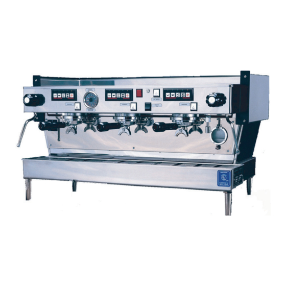
- Page 4 Machine Overview, Linea 13 14 1. Steam Knob, Left 8. Steam Knob, Right 2. Keypad 9. Main Switch 3. Semi-automatic Dispense Switch 10. Portafilter 4. Dual-scale Pressure Gauge 11. Group Head 5. Coffee Boiler Heating Element Indicator Light 12. Hot Water Nozzle 13.
- Page 5 2. Keypads The keypads contain up to four seperate product buttons, single ristretto, single shot, double ristretto, and double shot. Generally, the buttons are programmed to dispense 3/4 oz, 1 oz, 1-1/2 oz, and 2 ounces respectively, but they can be programmed to any desired volume.
- Page 6 7. Manual Fill Switch Depressing this switch activates the auto-fill valve, allowing cold water to flow into the steam boiler. This switch would only be used if the fuse in the control box has blown. 9. Main Switch The main power switch has three positions: OFF, FILL and RUN (or 0,1,2 on older ma- chines.) Off - The machine is off Fill - The electonics are activated, but NOT the heating elements.
- Page 7 12. Hot Water Nozzle The hot water nozzle is installed on the outlet of the hot water valve. When the valve is energized, hot water from the steam boiler is forced, by steam pressure, through the valve and out of the nozzle. 13.
-
Page 8: Water Requirements
Installation Contents When unpacking the machine, the following items should be included: * 4 NSF Legs (6 for a 4 group machine) * Pump & motor assembly * Portafilters * Drain Hose * Tamper * PuroCaff Cleaner * Owners manual * Inlet hoses, 24”, 48”, and 84”... - Page 9 First time machine start-up Once the machine has been properly installed: * Turn on the water supply. * The coffee boiler(s) will automatically begin to fill. * Locate the group caps and loosen the bleed screw 1/4 turn until a water bead is visible. Once a water bead is visible, re-tighten the bleed screw snugly.
- Page 10 Temperature and Pressure Adjustments Machines ship from ESI with the coffee boiler thermostat adjusted to heat and brew water for espresso at 197 degrees Fahrenheit or 92 degrees Celsius. If you prefer to adjust the tempera- ture to fit your coffee roast perform the following: * Make certain that the machine is at operating temperature and that the coffee boiler heating indicator light is off.
- Page 11 Section 1 Questionnaire 1. What’s unique about the La Marzocco espresso machine compared to other traditional machines on the market? 2. Why are two boilers in an espresso machine better than having only one? A. The heat exchangers require less maintenance. B.
- Page 12 10. What are the proper steps to take when programming the machine? A. Turn the machine offand hold down the continuous pour button while turning the machine B. Press and hold the continuous pour button until the LED above the button illuminates. Then press the button you wish to program.
- Page 13 4. Hydraulic System Tubing and fittings * Virtually all of the fittings on the LaMarzocco are of the compression or flare type. Most are made from brass, which will strip or crack if over-tightened. * It is important when working with tubing not to bend or twist the sections you are working with, as this will restrict the water flow or cause fatigue or leaks in the tubing.
- Page 14 Group Valves Each group has a three-way solenoid valve mounted underneath each head to allow for water flow through the group. Valve Piston * Each valve consist of valve body, valve stem, spring-loaded Valve Body piston and a coil. Solenoid Coil * The valve is mechanically closed by spring pressure.
- Page 15 Vacuum Breaker Top Cap The vacuum breaker is a mechanical valve located on the steam boiler. Gasket As pressure builds in the boiler, steam pressure lifts a plunger, sealing Teflon Cone the boiler, allowing steam pressure to increase above atmospheric Body pressure.
- Page 16 * Note - The boilers shown are from an EE, semi-automatic machine, an AV model would have flowmeters. 1. Circulation of water within the boiler and group head. 2. Water flow during the brew cycle. 3. Discharge of water after completion of brewing cycle...
- Page 18 Hydraulic Lines and Components 1. Inlet water tube to the coffee boiler. 2. Inlet water line feeding the inlet manifold. 3. Inlet water tube to the steam boiler. 4. Expansion valve. 5. Discharge fitting. 6. Discharge from the 3-way group valve. 7.
- Page 20 Section 2 Questionnaire 1. What material are the machines tubes made from? What precaution should you take in working with them? 2. What is the order of water flow while brewing in an AV machine? A. Banjo tube, group, flowmeter, group valve, diffuser block. B.
- Page 21 10. Identify the hydraulic compents in the above picture.
-
Page 22: Electrical System
5. Electrical System Safety * Always ensure power is off at the circuit breaker before removing or cutting any wires on the machine. * Never apply power to the machine without first insuring that all connections are properly insulated and no live wires are touching the frame. * Never replace a wire or fuse in a machine that is not of the same rating as the one you are replac ing. - Page 23 Solenoid Coils The solenoid valves operate by energizing an electromagnetic coil that causes a valve piston to move downward, opening the valve. * Test the coil by turning the machine off and disconnecting the wires, then read between the left and right terminal with a multi-meter.
- Page 24 Control Box The control box is the most complicated piece in the machine. It Non-Mask & Mask can be divided into the following systems: * Power supply - Turns high AC voltage into 18 volts DC (to power the board relays), and 5 volts DC (to power the microprocessor and logic circuits.) * Auto-fill sensing circuit - Sends power to the auto-fill probe looking for ground.
-
Page 25: Pressure Switch
Pressure Switch The pressure switch controls the steam pressure in the rear boiler by opening and closing the elec- trical circuit to the heating element. * The pressure switch receives power generally to the bottom set of input leads. When the steam pressure lowers in the boiler (usually .9 to 1.0 bar) the contacts close allowing power to flow from the bottom leads through to the top leads and then to the heating element. - Page 28 Non Mask control box and keypads use 8 pin connectors. Control box has internal pro- gramming key attachment. Keypad has all red LED’s and square buttons. Non-Mask Mask control box and keypads use 10 pin connectors. Program- ming key connection is external, located on the bottom pin set.
- Page 29 Section 3 Questionnaire 1. What safety precaution should be adhered to before performing maintenance on any electrical component, apart from taking voltage and amperage readings? 2. Which statement best describes the La Marzocco’s high voltage circuit operation? A. Each high-volt component receives 0 volts while the machine is operational. When the keypad or semi-automatic brew switch is activated, 110 volts flows to the component to activate it.
- Page 30 Troubleshooting Manual...
-
Page 31: Table Of Contents
Table of Contents Problem 1 - Shot volumes are inconsistent. Solution 1 - Limit rinsing of the portafilters with water from the brew group. Page 32 Solution 2 - Inspect the flowmeter for proper operation. Page 32 Solution 3 - Ensure the group heads are bled of any air. Page 33 Solution 4 - Check for and repair a faulty ground connection. -
Page 32: Problem 1 - Shot Volumes Are Inconsistent
Problem 1 - Shot volumes are inconsistent. Solution 1 - Limit rinsing of the portafilters with water from the brew group. Excessive rinsing of the portafilters with water from the brew group will gradually drive down the temperature in the brew boiler. This lowering of the brew temp will result in espresso shots that are less than ideal: weak extraction, very little crema, and unusually high volume. -
Page 33: Solution 3 - Ensure The Group Heads Are Bled Of Any Air
4. Remove the three 5. Remove the 6. Inspect the impel- 7. Inpect the flow- screws that secure the flowmeter field. lor for smooth rotation meter jet for scale field to the flowmeter and scale build-up on build-up. Clean out the body. -
Page 34: Solution 4 - Check For And Repair A Faulty Ground Connection
Solution 4 - Check for and repair a faulty ground connection. The control board on the AV, or automatic models, as well as the auto-fill board on the EE or semi-automatic models, each have step-down transformers that drop 220vac down to 24vac. The voltage that has been dropped down is then passed through a rectifyer which converts the AC voltage into DC voltage. -
Page 35: Solution 1 - Check The Fuse On The Control Board
Problem 2 - The buttons on the keypad won’t respond, but the manual override does. Solution 1 - Check the fuse on the control board. The control board stores the shot volume settings and controls the auto-fill circuit. The control board uses a 6.3 amp fuse to protect it against damage due to faulty electrical/electronic components. -
Page 36: Solution 2 - Check The Keypads For Proper Operation
Solution 2 - Check the keypads for proper operation. The keypads allow the operator to program shots to the desired volume, and to engage the pre-infu- sion feature. The keypads are connected to the controller by an 8 - 16 pin ribbon cable (depending on model). -
Page 37: Problem 3 - A Single Led Flashes Above A Selected Keypad Product Button
Problem 3 - A single LED flashes above a selected keypad product button. Solution 1 - Ensure the grind is not too fine and/or the tamp too hard. If the grind is too fine and/or the tamp too hard, water-flow may be restricted. This slows down or stops the movement of the flowmeter’s impellor causing the control board to not register a proper pulse signal. -
Page 38: Solution 3 - Inspect The Flowmeter For Proper Operation
Solution 3 - Inspect the flowmeter for proper operation. On automatic models, the flowmeter measures the quantity of water flowing to the brew group. The flowmeter uses an impeller imbedded with two magnets to actuate a hal effect switch to send pulse signals to the control box. -
Page 39: Problem 4 - All Of The Leds On Every Keypad Are Blinking
Problem 4 - All of the LEDs on every keypad are blinking. The autofill valve allows water to flow into the steam boiler. The control board on the machine will not allow the autofill valve to remain activated for no more than approximately 120 seconds. If the autofill valve remains activated for more than 120 seconds, the machine will shut power to the au- tofill coil off, and cause all of the LEDs on every keypad to start blinking to indicate that the autofill circuit has timed-out. - Page 40 10. Remove the valve 11. Inspect the 12. Reinstall the valve 9. Using a 22 mm stem and plunger. plunger for a dam- plunger and stem. wrench, loosen the aged or worn seal. Reinstall the stem to valve stem from the Inspect the valve the valve body.
-
Page 41: Problem 5 - The Espresso Seems Cold And Under-Extracted
Problem 5 - The espresso seems cold and under-extracted. Solution 1 - Limit rinsing of the portafilters with water from the brew group. Excessive rinsing of the portafilters with water from the brew group will gradually drive down the temperature in the brew boiler. This lowering of the brew temp will result in espresso shots that are less than ideal: weak extraction, very little crema, and unusually high volume. -
Page 42: Solution 3 - Adjust The Coffee Boiler's Thermostat, Replace If Necessary
Solution 3 - Adjust the coffee boiler’s thermostat. Replace if necessary. The temperature in the coffee boiler is controlled by a thermostat. If the thermostat is set improperly or is not functioning properly, the water temperature for brewing espresso will be inconsitent, re- sulting in espresso shots that are less than ideal. - Page 43 8. Remove the upper wire. 7. Remove the blue and 9. Remove the upper gauge white wires from the lower tube and carefully move it to portion of the thermostat. the side. 10. Remove the lower 12. Gently flex the panel 11.
-
Page 44: Problem 6 - The Dispensing Pressure Is Incorrect
Problem 6 - The dispensing pressure is incorrect. Solution 1 - Adjust the external boost pump. The water pressure required to properly brew espresso is 9 bar. Most municipalities supply water between 3-5 bar. Most espresso machines incorporate a boost pump to increase the in- coming water pressure to the required 9 bar to properly brew. -
Page 45: Problem 8 - No Steam Pressure
Problem 8 - No steam pressure. If no steam pressure is present in the steam boiler, there are several items to check. The main power switch, the heating element, and the pressure switch. Solution 1 - Ensure the main power switch is in the proper postition. 1. -
Page 46: Solution 2.1 - Replace The Heating Element
Solution 2.1 - Replacing the heating element. 1. Turn the machine off and 2. Remove the machines 3. Trim the heat-shrink depressurize the steam boiler. top and left side panel. from the heating element Remove the 5mm bolt located at terminals. -
Page 47: Solution 3 - Ensure The Pressure Switch Is Functioning Properly
Solution 3 - Ensure the pressure switch is functioning properly. The pressure switch controls the steam pressure in the steam boiler. The pressure switch uses a spring-loaded diaphragm to open and close a set of contacts, controlling electrical power to the heating element. -
Page 48: Problem 9 - The Steam Assembly And/Or Wand Is Leaking
Problem 9 - The steam assembly and/or wand is leaking. Solution 1 - Rebuild the steam assembly. 1. Remove the machines 2. Turn off the steam supply ball 3. Using the flat side of top panel and turn the ball valve and open the steam knob to a foam knife, unscrew valve off on the appropriate... - Page 49 o-rings gasket spring 13. When the shaft is dissas- 14. Remove the shaft end 15. Then carefully pry out sembled, you should have gasket by prying an awl or the old gasket. 2 o-rings, 1 bushing, and 1 gasket pick into the gas- spring.
- Page 50 25. Install the wand spring 27. Reinstall the steam 26. Compress washer and and washer. assembly onto the ma- spring and install the new chine. snap-ring 28. Install the valve re- 30. Tighten the retaining 29. Reposition and install taining nut. nut and supply tube simul- the steam supply tube.
-
Page 51: Problem 10 - Water Leaks From Around The Portafilter While Brewing
Problem 10 - Water leaks from around the portafilter while brewing. Solution 1 - Replace the portafilter gaskets. 2. The diffuser screen 1. Using a stubby flat-tip 3. Using an awl or gasket should come off with the screwdriver, remove the pick. -
Page 52: Problem 11 - Shot Volumes Are Consistently Short
Problem 11 - Shot volumes are consistently short.. Solution 1 - Replace the group valve plungers. Each group valve has a plunger that is mechanically closed, preventing water flow to the group head. The plunger is electromagnetically opened by the solenoid coil, allowing water flow to the group. - Page 53 10. Seperate the stem from 11. Inspect the plunger seat 12. Install a new plunger and the body and remove the for evidence of excessive ensure it travels smoothly in plunger. wear. Replace if necessary. the stem. 13. Reassemble the 14.
-
Page 54: Problem 12 - The Steam Boiler Overfills
Problem 12 - The steam boiler overfills. There are generally two reasons the steam boiler over-fills, a foreign object lodged in the auto- fill valve allowing water to slowly seep into the boiler causing it to over fill, or the auto-fill probe can build-up with scale deposits due to excessively hard water. -
Page 55: Solution 2 - Inspect The Auto-Fill Probe For Scale Build-Up
9. Using a 22 mm 10. Remove the valve 12. Reinstall the 11. Inspect the plunger wrench, loosen the stem and plunger. valve plunger and for a damaged or worn valve stem from the stem. Reinstall the seal. Inspect the valve valve body. -
Page 56: Problem 13 - No Water Flow From The Grouphead
Problem 13 - No water flow from the group head. There are several reasons for lack of water flow from the group while trying to brew. 1. The flowmeter is clogged with hard water scale deposits. 2. The group valve is faulty or clogged. 3. - Page 57 3/8" Cold COUNTERTOP VIEW Water Supply All Electrical and Plumbing Must meet Local Codes SIDE VIEW Franke Coffee Systems Phone 206 784 9563 / 800 367 0235 North America, Inc. Fax 206 782 2124 5601 1 st Avenue South www.franke-cs.com...
- Page 58 Water Supply All Electrical and Plumbing Must meet Local Codes S I D E V I E W Franke Coffee Systems Phone 206 784 9563 / 800 367 0235 North America, Inc. Fax 206 782 2124 5601 1 st Avenue South www.franke-cs.com...
- Page 59 3/8" Cold COUNTERTOP VIEW Water Supply All Electrical and Plumbing Must meet Local Codes SIDE VIEW Franke Coffee Systems Phone 206 784 9563 / 800 367 0235 North America, Inc. Fax 206 782 2124 5601 1 st Avenue South www.franke-cs.com...
- Page 60 COUNTE R TOP VIE W Water Supply All Electrical and Plumbing Must meet Local Codes S IDE VIE W Franke Coffee Systems Phone 206 784 9563 / 800 367 0235 North America, Inc. Fax 206 782 2124 5601 1 st Avenue South www.franke-cs.com...
- Page 61 Please check each box and obtain the store manager’s signature verifying that all requirements have been met. *The installer will be notified of a tentative date for this upcoming installation. *Franke Coffee Systems is not financially responsible for trips to sites that do not meet pre-installation re- quirements. Electrical Requirements □ 208–240 volt, 50/60 hz, single phase power on its own 50 amp circuit breaker...
- Page 62 Recommended Periodic Maintenance Schedule At 3 Months Rebuild the steam assemblies Replace the portafilter gaskets Clean the auto-fill probe Ensure the shot volumes are correct Replace the grinder burrs Ensure the brew temperature is correct At 6 Months Rebuild the steam assemblies Replace the portafilter gaskets Clean the auto-fill probe Ensure the shot volumes are correct...
- Page 63 Linea and GB-5 Minor A Scheduled Maintenance Checklist Tasks covered in the La Marzocco Troubleshooting Guide are indicated by TSG followed by the appropriate page numbers. Maintenance to be Performed Completed Replace Portafilter Gaskets ………………………...… ..........Rebuild Steam Assemblies…………………………… ..........Clean Auto-fill Probe....................
- Page 64 Linea and GB-5 Minor B Scheduled Maintenance Checklist Tasks covered in the La Marzocco Troubleshooting Guide are indicated by TSG followed by the appropriate page numbers. Maintenance to be Performed Completed Replace Portafilter Gaskets ................... Rebuild Steam Assemblies ................... Check Portafilter Baskets and replace if necessary ..........(This item is to be completed upon customer approval and is billable to the customer) Replace Diffuser Screens ..................
- Page 65 Linea and GB-5 Major A Scheduled Maintenance Checklist Tasks covered in the La Marzocco Troubleshooting Guide are indicated by TSG followed by the appropriate page numbers. Maintenance to be Performed Completed Replace Portafilter Gaskets......................Rebuild Steam Assemblies......................Check Portafilter Baskets and replace if necessary ............... (This item is to be completed upon customer approval and is billable to the customer) Replace Diffuser Screens......................
- Page 66 1 per group L100/H PLUNGER, SOLENOID VALVE $ 39.35 1 per group L116/A DOUBLE BASKET $ 6.49 Cost* for: 2 Group - $308.46; 3 Group – $382.63; 4 Group - $465.80 *Prices subject to change. Confirm with Franke Customer Support.
- Page 67 1 per group LAD070/V FLOW METER IMPELLOR $ 19.32 1 per group L100/H PLUNGER, SOLENOID VALVE $ 39.35 Cost* for: 2 Group - $268.24; 3 Group - $335.82; 4 Group - $403.50 *Prices subject to change. Confirm with Franke Customer Support.
Need help?
Do you have a question about the La Marzocco GB5 and is the answer not in the manual?
Questions and answers