GE F35 Instruction Manual
Multiple feeder protection system
Hide thumbs
Also See for F35:
- Instruction manual (682 pages) ,
- Communications manual (532 pages) ,
- Communications manual (526 pages)

Related Manuals for GE F35


Summary of Contents for GE F35
- Page 1 Digital Energy Multiple Feeder Protection System Instruction Manual Product version: 7.3x GE publication code: 1601-0106-AB1 (GEK-119617) E83849 LISTED IND.CONT. EQ. 52TL 1601-0106-AB1...
- Page 2 The contents of this manual are the property of GE Multilin Inc. This documentation is furnished on license and may not be reproduced in whole or in part without the permission of GE Multilin. The content of this manual is for informational use only and is subject to change without notice.
-
Page 3: Table Of Contents
Unpack and inspect ..................3-1 Panel cutouts ....................3-2 3.2.1 Horizontal units ........................3-2 3.2.2 Vertical units..........................3-3 3.2.3 Rear terminal layout ......................3-7 Wiring ......................... 3-9 3.3.1 Typical wiring ........................... 3-9 3.3.2 Dielectric strength........................3-10 F35 MULTIPLE FEEDER PROTECTION SYSTEM – INSTRUCTION MANUAL... - Page 4 4.2.5 Changing settings........................ 4-14 4.2.6 Faceplate ..........................4-15 4.2.7 LED indicators........................4-17 4.2.8 Custom LED labeling ......................4-20 4.2.9 Breaker control ........................4-26 4.2.10 Change passwords ......................4-27 4.2.11 Invalid password entry...................... 4-28 F35 MULTIPLE FEEDER PROTECTION SYSTEM – INSTRUCTION MANUAL...
- Page 5 Grouped elements..................5-155 5.7.1 Overview..........................5-155 5.7.2 Setting group 1........................5-155 5.7.3 Phase current........................5-156 5.7.4 Neutral current........................5-164 5.7.5 Wattmetric ground fault ....................5-166 5.7.6 Ground current........................5-170 5.7.7 Negative sequence current..................5-173 5.7.8 Voltage elements.......................5-175 Control elements ..................5-180 F35 MULTIPLE FEEDER PROTECTION SYSTEM – INSTRUCTION MANUAL...
- Page 6 6.1.19 Teleprotection channel tests.....................6-9 6.1.20 Incipient fault detector......................6-9 6.1.21 Remaining connection status ..................6-10 6.1.22 Parallel Redundancy Protocol (PRP) ................6-10 Metering ......................6-11 6.2.1 Metering conventions ......................6-11 6.2.2 Sources ............................. 6-15 F35 MULTIPLE FEEDER PROTECTION SYSTEM – INSTRUCTION MANUAL...
- Page 7 10.6.1 Replace battery for RH/RL power supply..............10-7 10.6.2 Replace battery for SH/SL power supply ..............10-8 10.6.3 Dispose of battery........................10-9 10.7 Clear files and data after uninstall ............10-12 A FLEXANALOG A.1 FlexAnalog items .....................A-1 OPERANDS F35 MULTIPLE FEEDER PROTECTION SYSTEM – INSTRUCTION MANUAL...
- Page 8 TABLE OF CONTENTS B RADIUS SERVER B.1 RADIUS server configuration .................B-1 CONFIGURATION C MISCELLANEOUS C.1 Warranty ......................C-1 C.2 Revision history ....................C-1 ABBREVIATIONS INDEX viii F35 MULTIPLE FEEDER PROTECTION SYSTEM – INSTRUCTION MANUAL...
-
Page 9: Introduction
Ensure that the control power applied to the device, the AC current, and voltage input match the ratings specified on the relay nameplate. Do not apply current or voltage in excess of the specified limits. F35 MULTIPLE FEEDER PROTECTION SYSTEM – INSTRUCTION MANUAL... -
Page 10: For Further Assistance
Worldwide telephone: +1 905 927 7070 Europe/Middle East/Africa telephone: +34 94 485 88 54 North America toll-free: 1 800 547 8629 Fax: +1 905 927 5098 Worldwide e-mail: multilin.tech@ge.com Europe e-mail: multilin.tech.euro@ge.com Website: http://www.gedigitalenergy.com/multilin F35 MULTIPLE FEEDER PROTECTION SYSTEM – INSTRUCTION MANUAL... -
Page 11: Product Description
2.1 Product description The F35 Multiple Feeder Protection System is part of the Universal Relay (UR) series of products. It is a microprocessor- based relay that protects up to five feeders with busbar voltage measurement or up to six feeders without busbar voltage. - Page 12 Metering: current, voltage, power, energy, User-programmable self-tests frequency, harmonics, THD Digital elements (48) Modbus user map Virtual inputs (64) Direct inputs and outputs (32) Non-volatile latches Virtual outputs (96) Disconnect switches Non-volatile selector switch F35 MULTIPLE FEEDER PROTECTION SYSTEM – INSTRUCTION MANUAL...
-
Page 13: Security
The F35 supports password entry from a local or remote connection. Local access is defined as any access to settings or commands via the faceplate interface. This includes both keypad entry and the through the faceplate RS232 port. Remote access is defined as any access to settings or commands via any rear communications port. - Page 14 Complete access Complete access Command Authorizes Default role except for menu writing CyberSentry Security Device Definition Settings |---------- Product Setup |--------------- Security (CyberSentry) |--------------- Supervisory See table notes See table notes |--------------- Display Properties F35 MULTIPLE FEEDER PROTECTION SYSTEM – INSTRUCTION MANUAL...
- Page 15 |--------------- Direct Analogs |--------------- Direct Integers |---------- Transducer I/O |---------- Testing |---------- Front Panel Labels Designer |---------- Protection Summary Commands |---------- Virtual Inputs |---------- Clear Records |---------- Set Date and Time User Displays Targets F35 MULTIPLE FEEDER PROTECTION SYSTEM – INSTRUCTION MANUAL...
-
Page 16: Order Codes
The order code is on the product label and indicates the product options applicable. The F35 is available as a 19-inch rack horizontal mount or reduced-size (¾) vertical unit. It consists of the following modules: power supply, CPU, CT/VT, contact input and output, transducer input and output, and inter-relay communications. -
Page 17: Order Codes With Enhanced Ct/Vt Modules
CHAPTER 2: PRODUCT DESCRIPTION ORDER CODES 2.3.1 Order codes with enhanced CT/VT modules Table 2-4: F35 order codes for horizontal units - * * * - F ** - H ** - M ** - U ** - W/X Full Size Horizontal Mount... - Page 18 Channel 1 - G.703; Channel 2 - 1300 nm, single-mode Laser G.703, 1 Channel G.703, 2 Channels RS422, 1 Channel RS422, 2 Channels Table 2-5: F35 order codes for reduced-size vertical units - * * - F ** - H ** - M **...
- Page 19 Channel 1 - RS422; Channel 2 - 1300 nm, single-mode, Laser Channel 1 - G.703; Channel 2 - 1300 nm, single-mode Laser G.703, 1 Channel G.703, 2 Channels RS422, 1 Channel RS422, 2 Channels F35 MULTIPLE FEEDER PROTECTION SYSTEM – INSTRUCTION MANUAL...
-
Page 20: Order Codes With Process Bus Modules
ORDER CODES CHAPTER 2: PRODUCT DESCRIPTION 2.3.2 Order codes with process bus modules Table 2-6: F35 order codes for horizontal units with process bus - * * - F ** - H ** - M ** - U ** - W/X... - Page 21 Channel 1 - G.703; Channel 2 - 1300 nm, single-mode Laser G.703, 1 Channel G.703, 2 Channels RS422, 1 Channel RS422, 2 Channels Table 2-7: F35 order codes for reduced-size vertical units with process bus - * * - F ** - H ** - M **...
-
Page 22: Replacement Modules
Replacement modules can be ordered separately. When ordering a replacement CPU module or faceplate, provide the serial number of your existing unit. Not all replacement modules apply to the F35 relay. The modules specified in the order codes for the F35 are available as replacement modules for the F35. - Page 23 Standard 4CT/4VT with enhanced diagnostics Standard 8CT with enhanced diagnostics Standard 8VT with enhanced diagnostics INTER-RELAY COMMUNICATIONS C37.94SM, 1300 nm single-mode, ELED, 1 channel single-mode C37.94SM, 1300 nm single-mode, ELED, 2 channel single-mode F35 MULTIPLE FEEDER PROTECTION SYSTEM – INSTRUCTION MANUAL 2-13...
-
Page 24: Specifications
> 2.0 CT: ±1.5% of reading > 2.0 CT rating Curve shapes: IEEE Moderately/Very/Extremely Inverse; IEC (and BS) A/B/C and Short Inverse; GE IAC Inverse, Short/Very/ Extremely Inverse; I t; FlexCurves™ (programmable); Definite Time (0.01 s base... - Page 25 0.1 to 2.0 x CT rating ±1.5% of reading > 2.0 x CT rating Curve shapes: IEEE Moderately/Very/Extremely Inverse; IEC (and BS) A/B/C and Short Inverse; GE IAC Inverse, Short/Very/ Extremely Inverse; I t; FlexCurves™ (programmable); Definite Time (0.01 s base...
- Page 26 0.000 to 65.535 s in steps of 0.001 Operating mode: number of counts, counts per time window AUTORECLOSURE Single breaker applications, 3-pole tripping schemes Up to four reclose attempts before lockout 2-16 F35 MULTIPLE FEEDER PROTECTION SYSTEM – INSTRUCTION MANUAL...
-
Page 27: User-Programmable Elements
20 ms to 60 days Pickup and dropout delay: 0.000 to 65.535 s in steps of 0.001 NON-VOLATILE LATCHES Type: set-dominant or reset-dominant Number: 16 (individually programmed) Output: stored in non-volatile memory F35 MULTIPLE FEEDER PROTECTION SYSTEM – INSTRUCTION MANUAL 2-17... - Page 28 FlexLogic operand Pickup delay: 0.000 to 999999.999 s in steps of 0.001 Dropout delay: 0.000 to 999999.999 s in steps of 0.001 Timing accuracy: ±3% or ±4 ms, whichever is greater 2-18 F35 MULTIPLE FEEDER PROTECTION SYSTEM – INSTRUCTION MANUAL...
-
Page 29: Monitoring
±1.0% of reading RMS VOLTAGE Accuracy: ±0.5% of reading from 10 to 208 V REAL POWER (WATTS) Accuracy at 0.1 to 1.5 x CT rating and 0.8 to 1.2 x VT rating: F35 MULTIPLE FEEDER PROTECTION SYSTEM – INSTRUCTION MANUAL 2-19... -
Page 30: Inputs
1 sec at 100 times rated continuous 4xInom Short circuit rating: 150000 RMS symmetrical amperes, 250 V maximum (primary current to external CT) AC VOLTAGE VT rated secondary: 50.0 to 240.0 V 2-20 F35 MULTIPLE FEEDER PROTECTION SYSTEM – INSTRUCTION MANUAL... - Page 31 1 to 10 V pk-pk DC shift: TTL–Compatible Input impedance: 50 k Isolation: 2 kV DIRECT INPUTS Input points: Remote devices: Default states on loss of comms.: On, Off, Latest/Off, Latest/On Ring configuration: Yes, No F35 MULTIPLE FEEDER PROTECTION SYSTEM – INSTRUCTION MANUAL 2-21...
-
Page 32: Power Supply
4 A / 250 V Interrupting capacity: 100 000 A RMS symmetrical 10 000 A 2.4.7 Outputs FORM-A RELAY Make and carry for 0.2 s: 30 A as per ANSI C37.90 Carry continuous: 2-22 F35 MULTIPLE FEEDER PROTECTION SYSTEM – INSTRUCTION MANUAL... - Page 33 48 V 0.5 A 125 V 0.3 A 250 V 0.2 A Operate time: < 8 ms Contact material: silver alloy FAST FORM-C RELAY Make and carry: 0.1 A max. (resistive load) F35 MULTIPLE FEEDER PROTECTION SYSTEM – INSTRUCTION MANUAL 2-23...
- Page 34 99% Settling time to a step change: 100 ms Isolation: 1.5 kV Driving signal: any FlexAnalog quantity Upper and lower limit for the driving signal: –90 to 90 pu in steps of 0.001 2-24 F35 MULTIPLE FEEDER PROTECTION SYSTEM – INSTRUCTION MANUAL...
-
Page 35: Communications
PARALLEL REDUNDANCY PROTOCOL (PRP) (IEC 62439-3 CLAUSE 4, 2012) Ethernet ports used: 2 and 3 Networks supported: 10/100 Mb Ethernet OTHER TFTP, SFTP, HTTP, IEC 60870-5-104, Ethernet Global Data (EGD), IEEE C37.118 F35 MULTIPLE FEEDER PROTECTION SYSTEM – INSTRUCTION MANUAL 2-25... -
Page 36: Inter-Relay Communications
820 nm LED, Multimode –7.6 dBm 1300 nm LED, Multimode –11 dBm 1300 nm ELED, Single mode –14 dBm 1300 nm Laser, Single mode –14 dBm 1550 nm Laser, Single mode –14 dBm 2-26 F35 MULTIPLE FEEDER PROTECTION SYSTEM – INSTRUCTION MANUAL... -
Page 37: Environmental
HUMIDITY Humidity: operating up to 95% (non-condensing) at 55°C (as per IEC60068-2-30 variant 1, 6 days) OTHER Altitude: 2000 m (maximum) Pollution degree: Overvoltage category: Ingress protection: IP20 front, IP10 back F35 MULTIPLE FEEDER PROTECTION SYSTEM – INSTRUCTION MANUAL 2-27... -
Page 38: Type Tests
IEC 60255-27 Insulation: class 1, Pollution degree: 2, Over voltage cat II 2.4.12 Production tests THERMAL Products go through an environmental test based upon an Accepted Quality Level (AQL) sampling process. 2-28 F35 MULTIPLE FEEDER PROTECTION SYSTEM – INSTRUCTION MANUAL... -
Page 39: Approvals
Normally, cleaning is not required. When dust has accumulated on the faceplate display, wipe with a dry cloth. To avoid deterioration of electrolytic capacitors, power up units that are stored in a de-energized state once per year, for one hour continuously. F35 MULTIPLE FEEDER PROTECTION SYSTEM – INSTRUCTION MANUAL 2-29... - Page 40 SPECIFICATIONS CHAPTER 2: PRODUCT DESCRIPTION 2-30 F35 MULTIPLE FEEDER PROTECTION SYSTEM – INSTRUCTION MANUAL...
-
Page 41: Installation
For any issues, contact GE Digital Energy as outlined in the For Further Assistance section in chapter 1. Check that you have the latest copy of the F35 Instruction Manual and the UR Series Communications Guide, for the applicable firmware version, at http://gedigitalenergy.com/multilin/manuals/index.htm... -
Page 42: Panel Cutouts
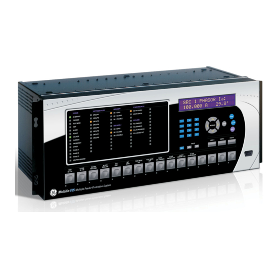
This section does not apply to the HardFiber Brick; see its instruction manual. 3.2.1 Horizontal units The F35 is available as a 19-inch rack horizontal mount unit with a removable faceplate. The faceplate can be specified as either standard or enhanced at the time of ordering. The enhanced faceplate contains additional user-programmable pushbuttons and LED indicators. -
Page 43: Vertical Units
3.2.2 Vertical units The F35 is available as a reduced size (¾) vertical mount unit, with a removable faceplate. The faceplate can be specified as either standard or enhanced at the time of ordering. The enhanced faceplate contains additional user-programmable pushbuttons and LED indicators. - Page 44 RS232 communications port. The relay is secured to the panel with the use of four screws supplied with the relay. Figure 3-4: Vertical dimensions (enhanced panel) F35 MULTIPLE FEEDER PROTECTION SYSTEM – INSTRUCTION MANUAL...
- Page 45 CHAPTER 3: INSTALLATION PANEL CUTOUTS Figure 3-5: Vertical and mounting dimensions (standard panel) For details on side-mounting F35 devices with the enhanced front panel, see the following documents available on the UR DVD and the GE Digital Energy website. •...
- Page 46 PANEL CUTOUTS CHAPTER 3: INSTALLATION For details on side-mounting F35 devices with the standard front panel, see the following figures. Figure 3-6: Vertical side-mounting installation (standard panel) F35 MULTIPLE FEEDER PROTECTION SYSTEM – INSTRUCTION MANUAL...
-
Page 47: Rear Terminal Layout
CHAPTER 3: INSTALLATION PANEL CUTOUTS Figure 3-7: Vertical side-mounting rear dimensions (standard panel) 3.2.3 Rear terminal layout Do not touch any rear terminals while the relay is energized. F35 MULTIPLE FEEDER PROTECTION SYSTEM – INSTRUCTION MANUAL... - Page 48 (nearest to CPU module), indicated by an arrow marker on the terminal block. The figure shows an example of rear terminal assignments. Figure 3-8: Example of modules in F and H slots F35 MULTIPLE FEEDER PROTECTION SYSTEM – INSTRUCTION MANUAL...
-
Page 49: Wiring
CHAPTER 3: INSTALLATION WIRING 3.3 Wiring 3.3.1 Typical wiring Figure 3-9: Typical wiring diagram (T module shown for CPU) F35 MULTIPLE FEEDER PROTECTION SYSTEM – INSTRUCTION MANUAL... -
Page 50: Dielectric Strength
The power supply module can be ordered for two possible voltage ranges, and the F35 can be ordered with or without a redundant power supply module option. Each range has a dedicated input connection for proper operation. The ranges are as follows (see the Specifications section of chapter 2 for details): •... -
Page 51: Ct/Vt Modules
CT connections for both ABC and ACB phase rotations are identical, as shown in the Typical Wiring Diagram. The exact placement of a zero-sequence core balance CT to detect ground fault current is shown as follows. Twisted-pair cabling on the zero-sequence CT is recommended. F35 MULTIPLE FEEDER PROTECTION SYSTEM – INSTRUCTION MANUAL 3-11... -
Page 52: Process Bus Modules
3.3.5 Process bus modules The F35 can be ordered with a process bus interface module. The module interfaces with the HardFiber Process Bus System, or HardFiber Brick, allowing bidirectional IEC 61850 fiber optic communications with up to eight HardFiber Bricks. -
Page 53: Contact Inputs And Outputs
The terminal configuration for contact inputs is different for the two applications. The contact inputs are grouped with a common return. The F35 has two versions of grouping: four inputs per common return and two inputs per common return. When a contact input/output module is ordered, four inputs per common is used. - Page 54 Where a tilde “~” symbol appears, substitute the slot position of the module. Where a number sign “#” appears, substitute the contact number. NOTE 3-14 F35 MULTIPLE FEEDER PROTECTION SYSTEM – INSTRUCTION MANUAL...
- Page 55 ~6a, ~6c 2 Inputs Fast Form-C ~7a, ~7c 2 Inputs ~7a, ~7c 2 Inputs ~7a, ~7c 2 Inputs Fast Form-C ~8a, ~8c 2 Inputs ~8a, ~8c 2 Inputs ~8a, ~8c 2 Inputs F35 MULTIPLE FEEDER PROTECTION SYSTEM – INSTRUCTION MANUAL 3-15...
- Page 56 ~5a, ~5c 2 Inputs 2 Outputs Solid-State Solid-State ~6a, ~6c 2 Inputs 2 Outputs Not Used Not Used ~7a, ~7c 2 Inputs 2 Outputs Solid-State Solid-State ~8a, ~8c 2 Inputs Not Used 3-16 F35 MULTIPLE FEEDER PROTECTION SYSTEM – INSTRUCTION MANUAL...
- Page 57 CHAPTER 3: INSTALLATION WIRING Figure 3-14: Contact input and output module wiring (Sheet 1 of 2) F35 MULTIPLE FEEDER PROTECTION SYSTEM – INSTRUCTION MANUAL 3-17...
- Page 58 DIGITAL I/O CONTACT IN SURGE CONTACT IN CONTACT IN CONTACT IN COMMON SURGE 842763A2.CDR For proper functionality, observe the polarity shown in the figures for all contact input and output connections. 3-18 F35 MULTIPLE FEEDER PROTECTION SYSTEM – INSTRUCTION MANUAL...
- Page 59 The contact inputs with auto-burnish create a high current impulse when the threshold is reached to burn off this oxidation layer as a maintenance to the contacts. Afterwards the contact input current is reduced to a steady-state current. The impulse has a five-second delay after a contact input changes state. F35 MULTIPLE FEEDER PROTECTION SYSTEM – INSTRUCTION MANUAL 3-19...
-
Page 60: Transducer Inputs And Outputs
Transducer input modules can receive input signals from external DCmA output transducers (DCmA In) or resistance temperature detectors (RTDs). Hardware and software are provided to receive signals from these external transducers and convert these signals into a digital format for use as required. 3-20 F35 MULTIPLE FEEDER PROTECTION SYSTEM – INSTRUCTION MANUAL... - Page 61 (5A, 5C, 5D, 5E, and 5F) and channel arrangements that can be ordered for the relay. Where a tilde “~” symbol appears, substitute the slot position of the module. NOTE Figure 3-19: Transducer input/output module wiring The following figure show how to connect RTDs. F35 MULTIPLE FEEDER PROTECTION SYSTEM – INSTRUCTION MANUAL 3-21...
-
Page 62: Rs232 Faceplate Port
The baud rate for this port can be set, with a default of 19200 bps. Figure 3-21: RS232 faceplate port connection 3.3.9 CPU communication ports 3.3.9.1 Overview In addition to the faceplate RS232 port, there is a rear RS485 communication port. 3-22 F35 MULTIPLE FEEDER PROTECTION SYSTEM – INSTRUCTION MANUAL... - Page 63 This common voltage is implied to be a power supply common. Some systems allow the shield (drain wire) to be used as common wire and to connect directly to the F35 COM terminal (#3); others function correctly only if the common wire is connected to the F35 COM terminal, but insulated from the shield.
-
Page 64: Irig-B
IRIG-B is a standard time code format that allows stamping of events to be synchronized among connected devices. The IRIG-B code allows time accuracies of up to 100 ns. Using the IRIG-B input, the F35 operates an internal oscillator with 1 µs resolution and accuracy. -
Page 65: Direct Input And Output Communications
UR-series relays with the following connections: UR1-Tx to UR2-Rx, UR2-Tx to UR3-Rx, UR3-Tx to UR4-Rx, and UR4-Tx to UR1-Rx. A maximum of 16 UR-series relays can be connected in a single ring. F35 MULTIPLE FEEDER PROTECTION SYSTEM – INSTRUCTION MANUAL 3-25... - Page 66 1 to channel 2 on UR2, set the setting to “Enabled” on UR2. This DIRECT I/O CHANNEL CROSSOVER forces UR2 to forward messages received on Rx1 out Tx2, and messages received on Rx2 out Tx1. 3-26 F35 MULTIPLE FEEDER PROTECTION SYSTEM – INSTRUCTION MANUAL...
-
Page 67: Fiber: Led And Eled Transmitters
The following figure shows the configuration for the 7A, 7B, 7C, 7H, 7I, and 7J fiber-only modules. Figure 3-28: LED and ELED fiber modules 3.4.3 Fiber laser transmitters The following figure shows the configuration for the 72, 73, 7D, and 7K fiber-laser modules. F35 MULTIPLE FEEDER PROTECTION SYSTEM – INSTRUCTION MANUAL 3-27... -
Page 68: Interface
The following figure shows the 64K ITU G.703 co-directional interface configuration. The G.703 module is fixed at 64 kbps. The setting is not SETTINGS PRODUCT SETUP DIRECT I/O DIRECT I/O DATA RATE applicable to this module. 3-28 F35 MULTIPLE FEEDER PROTECTION SYSTEM – INSTRUCTION MANUAL... - Page 69 Once the clips have cleared the raised edge of the chassis, engage the clips simultaneously. When the clips have locked into position, the module is inserted fully. F35 MULTIPLE FEEDER PROTECTION SYSTEM – INSTRUCTION MANUAL 3-29...
- Page 70 (S1 = ON) and set timing mode to loop timing (S5 = OFF and S6 = OFF). The switch settings for the internal and loop timing modes are shown. 3-30 F35 MULTIPLE FEEDER PROTECTION SYSTEM – INSTRUCTION MANUAL...
- Page 71 One source lies on the G.703 line side of the interface while the other lies on the differential Manchester side of the interface. Figure 3-36: G.703 dual loopback mode DMR = Differential Manchester Receiver DMX = Differential Manchester Transmitter G7X = G.703 Transmitter G7R = G.703 Receiver 842775A1.CDR F35 MULTIPLE FEEDER PROTECTION SYSTEM – INSTRUCTION MANUAL 3-31...
-
Page 72: Rs422 Interface
1 are also paralleled to the terminal timing inputs of data module 2. By using this configuration, the timing for both data modules and both UR RS422 channels are derived from a single clock 3-32 F35 MULTIPLE FEEDER PROTECTION SYSTEM – INSTRUCTION MANUAL... - Page 73 831022A3.CDR Data module 1 provides timing to the F35 RS422 interface via the ST(A) and ST(B) outputs. Data module 1 also provides timing to data module 2 TT(A) and TT(B) inputs via the ST(A) and AT(B) outputs. The data module pin numbers have been omitted in the figure because they vary by manufacturer.
-
Page 74: Rs422 And Fiber Interface
G.703 and fiber interfaces. When using a laser interface, attenuators can be necessary to ensure that you do not exceed the maximum optical input power to the receiver. 3-34 F35 MULTIPLE FEEDER PROTECTION SYSTEM – INSTRUCTION MANUAL... -
Page 75: Ieee C37.94 Interface
Connection — as per all fiber optic connections, a Tx to Rx connection is required The UR-series C37.94 communication module can be connected directly to any compliant digital multiplexer that supports the IEEE C37.94 standard. The figure shows the concept. F35 MULTIPLE FEEDER PROTECTION SYSTEM – INSTRUCTION MANUAL 3-35... - Page 76 Once the clips have cleared the raised edge of the chassis, engage the clips simultaneously. When the clips have locked into position, the module is inserted fully. 3-36 F35 MULTIPLE FEEDER PROTECTION SYSTEM – INSTRUCTION MANUAL...
- Page 77 Modules shipped since January 2012 have status LEDs that indicate the status of the DIP switches, as shown in the following figure. Figure 3-45: Status LEDs The clock configuration LED status is as follows: • Flashing green — loop timing mode while receiving a valid data packet F35 MULTIPLE FEEDER PROTECTION SYSTEM – INSTRUCTION MANUAL 3-37...
-
Page 78: C37.94Sm Interface
It also can be connected directly to any other UR-series relay with a C37.94SM module, as shown. The UR-series C37.94SM communication module has six switches that are used to set the clock configuration. The following figure shows the functions of these control switches. 3-38 F35 MULTIPLE FEEDER PROTECTION SYSTEM – INSTRUCTION MANUAL... - Page 79 Once the clips have cleared the raised edge of the chassis, engage the clips simultaneously. When the clips have locked into position, the module is inserted fully. F35 MULTIPLE FEEDER PROTECTION SYSTEM – INSTRUCTION MANUAL 3-39...
- Page 80 Modules shipped since January 2012 have status LEDs that indicate the status of the DIP switches, as shown in the following figure. Figure 3-48: Status LEDs The clock configuration LED status is as follows: • Flashing green — loop timing mode while receiving a valid data packet 3-40 F35 MULTIPLE FEEDER PROTECTION SYSTEM – INSTRUCTION MANUAL...
-
Page 81: Activate Relay
RELAY SETTINGS: NEW SETTING Not Programmed Programmed HAS BEEN STORED When the "NEW SETTING HAS BEEN STORED" message appears, the relay is in "Programmed" state and the "In Service" LED turns on. F35 MULTIPLE FEEDER PROTECTION SYSTEM – INSTRUCTION MANUAL 3-41... -
Page 82: Install Software
This device (catalog number F485) connects to the computer using a straight-through serial cable. A shielded twisted-pair (20, 22, or 24 AWG) connects the F485 converter to the F35 rear communications port. The converter terminals (+, –, GND) are connected to the F35 communication module (+, –, COM) terminals. See the CPU Communication Ports section in chapter 3 for details. -
Page 83: System Requirements
Ethernet port of the same type as one of the UR CPU ports or a LAN connection to the UR • Internet access or a DVD drive The following qualified modems have been tested to be compatible with the F35 and the EnerVista software: • US Robotics external 56K FaxModem 5686 •... -
Page 84: Configure The F35 For Software Access
3.7 Configure the F35 for software access You connect remotely to the F35 through the rear RS485 or Ethernet port with a computer running the EnerVista UR Setup software. The F35 also can be accessed locally with a computer through the front panel RS232 port or the rear Ethernet port using the Quick Connect feature. -
Page 85: Configure Serial Communication
3.7.1 Configure serial communication A computer with an RS232 port and a serial cable are required. To use the RS485 port at the back of the relay, a GE Digital Energy F485 converter (or compatible RS232-to-RS485 converter) is required. See the F485 instruction manual for details. -
Page 86: Configure Ethernet Communication
11. Click OK when the relay order code has been received. The new device is added to the Site List window (or Online window) located in the top left corner of the main EnerVista UR Setup window. The Site Device has now been configured for Ethernet communications. Proceed to the Connecting to the F35 section to begin communications. -
Page 87: Automatic Discovery Of Ur Devices
To access the relay in EnerVista: Open the Settings > Product Setup > Display Properties window as shown. The window opens with a status indicator on the lower left of the EnerVista UR Setup window. F35 MULTIPLE FEEDER PROTECTION SYSTEM – INSTRUCTION MANUAL 3-47... -
Page 88: Use Quick Connect Via The Front Panel Rs232 Port
Connect a nine-pin to nine-pin RS232 serial cable to the computer and the front panel RS232 port. Verify that the latest version of the EnerVista UR Setup software is installed (available from the GE EnerVista DVD or online from http://www.gedigitalenergy.com/multilin). See the software installation section if not already installed. -
Page 89: Use Quick Connect Via A Rear Ethernet Port
3.8.3 Use Quick Connect via a rear Ethernet port To use the Quick Connect feature to access the F35 from a computer through Ethernet, first assign an IP address to the relay using the front panel keyboard. Press the key until the menu displays. - Page 90 CONNECT TO THE F35 CHAPTER 3: INSTALLATION connections window. Right-click the Local Area Connection icon and select Properties. Select the Internet Protocol (TCP/IP) item from the list, and click the Properties button. 3-50 F35 MULTIPLE FEEDER PROTECTION SYSTEM – INSTRUCTION MANUAL...
- Page 91 CONNECT TO THE F35 Click the “Use the following IP address” box. Enter an IP address with the first three numbers the same as the IP address of the F35 relay and the last number different (in this example, 1.1.1.2).
- Page 92 If this computer is used to connect to the Internet, re-enable any proxy server settings after the computer has been disconnected from the F35 relay. Start the Internet Explorer software. Select the UR device from the EnerVista Launchpad to start EnerVista UR Setup. 3-52 F35 MULTIPLE FEEDER PROTECTION SYSTEM – INSTRUCTION MANUAL...
- Page 93 Click the Quick Connect button to open the window. Select the Ethernet interface and enter the IP address assigned to the F35, then click the Connect button. The EnerVista UR Setup software creates a site named “Quick Connect” with a corresponding device also named “Quick Connect”...
-
Page 94: Set Up Cybersentry And Change Default Password
If using EnerVista, navigate to Settings > Product Setup > Security. Change the Local Administrator Password, for example. It is strongly recommended that the password for the Administrator be changed from the default. Changing the passwords for the other three roles is optional. 3-54 F35 MULTIPLE FEEDER PROTECTION SYSTEM – INSTRUCTION MANUAL... - Page 95 CHAPTER 3: INSTALLATION SET UP CYBERSENTRY AND CHANGE DEFAULT PASSWORD Figure 3-60: Changing the default password F35 MULTIPLE FEEDER PROTECTION SYSTEM – INSTRUCTION MANUAL 3-55...
- Page 96 SET UP CYBERSENTRY AND CHANGE DEFAULT PASSWORD CHAPTER 3: INSTALLATION 3-56 F35 MULTIPLE FEEDER PROTECTION SYSTEM – INSTRUCTION MANUAL...
-
Page 97: Interfaces
The EnerVista UR Setup software is provided with every F35. This chapter outlines the EnerVista software interface features. The EnerVista UR Setup Help File also provides details for getting started and using the software interface. -
Page 98: Event Viewing
IP Address IP Subnet Mask IP Routing When a settings file is loaded to a F35 that is in-service, the following sequence occurs: The F35 takes itself out of service. The F35 issues a UNIT NOT PROGRAMMED major self-test error. -
Page 99: Settings Templates
(settings file templates) and online devices (online settings templates). The functionality is identical for both purposes. Settings files conversion from previous firmware versions is supported. F35 MULTIPLE FEEDER PROTECTION SYSTEM – INSTRUCTION MANUAL... - Page 100 By default, all settings are specified as locked and displayed against a grey background. The icon on the upper right of the settings window also indicates that the EnerVista software is in EDIT mode. The following example shows the phase time overcurrent settings window in edit mode. F35 MULTIPLE FEEDER PROTECTION SYSTEM – INSTRUCTION MANUAL...
- Page 101 The following procedure describes how to add password protection to a settings file template. Select a settings file from the offline window on the left of the EnerVista UR Setup window. Select the Template Mode > Password Protect Template option. F35 MULTIPLE FEEDER PROTECTION SYSTEM – INSTRUCTION MANUAL...
- Page 102 Viewing the settings in template mode also modifies the settings menu, showing only the settings categories that contain editable settings. The effect of applying the template to a typical settings menu is shown as follows. F35 MULTIPLE FEEDER PROTECTION SYSTEM – INSTRUCTION MANUAL...
- Page 103 Select an installed device or settings file on the left side of the EnerVista UR Setup window. Right-click and select the Template Mode > Remove Settings Template option. Enter the template password and click OK to continue. F35 MULTIPLE FEEDER PROTECTION SYSTEM – INSTRUCTION MANUAL...
-
Page 104: Secure And Lock Flexlogic Equations
Click the Save button to save and apply changes to the settings template. Select the Template Mode > View In Template Mode option to view the template. Apply a password to the template then click OK to secure the FlexLogic equation. F35 MULTIPLE FEEDER PROTECTION SYSTEM – INSTRUCTION MANUAL... - Page 105 Right-click the setting file in the offline window area and select the Edit Settings File Properties item. The window opens. F35 MULTIPLE FEEDER PROTECTION SYSTEM – INSTRUCTION MANUAL...
-
Page 106: Settings File Traceability
When a settings file is transferred to a F35 device, the date, time, and serial number of the F35 are sent back to EnerVista UR Setup and added to the settings file on the local computer. This information can be compared with the F35 actual values at any later date to determine if security has been compromised. - Page 107 With respect to the figure, the traceability feature is used as follows. The transfer date of a settings file written to a F35 is logged in the relay and can be viewed in the EnerVista software or the front panel display. Likewise, the transfer date of a settings file saved to a local computer is logged in the EnerVista software.
-
Page 108: Front Panel Interface
For example, for 127.0.0.1, press 127, then •, then 0, then •, then 0, then •, then 1. To save the address, press key. ENTER The figure shows the sequence to use to enter a setting. Subsequent sections provide more detail. 4-12 F35 MULTIPLE FEEDER PROTECTION SYSTEM – INSTRUCTION MANUAL... -
Page 109: Menu Navigation
Default values are indicated in this instruction manual in mixed case. In the example shown here, the default access level is Restricted. Highest level Lowest level (setting value) SETTINGS SECURITY ACCESS LEVEL: PRODUCT SETUP Restricted SETTINGS SYSTEM SETUP F35 MULTIPLE FEEDER PROTECTION SYSTEM – INSTRUCTION MANUAL 4-13... -
Page 110: Changing Settings
While at the maximum value, pressing the up arrow again allows the setting selection to continue VALUE upward from the minimum value. The down arrow decrements the displayed value by the step value, down to VALUE 4-14 F35 MULTIPLE FEEDER PROTECTION SYSTEM – INSTRUCTION MANUAL... -
Page 111: Faceplate
The front panel consists of LED panels, an RS232 port, keypad, LCD display, control pushbuttons, and optional user- programmable pushbuttons. The faceplate is hinged to allow access to the removable modules. F35 MULTIPLE FEEDER PROTECTION SYSTEM – INSTRUCTION MANUAL 4-15... - Page 112 User-programmable Keypad (control) pushbuttons 1 to 7 pushbuttons 1 to 12 827801A . The following figure shows the vertical arrangement of the faceplate panel for relays ordered with the vertical option. 4-16 F35 MULTIPLE FEEDER PROTECTION SYSTEM – INSTRUCTION MANUAL...
-
Page 113: Led Indicators
SETTINGS INPUT/OUTPUTS RESETTING keys are used by the breaker control feature. USER Figure 4-19: Typical LED panel for enhanced faceplate 842811A1.CDR The status indicators in the first column are as follows: F35 MULTIPLE FEEDER PROTECTION SYSTEM – INSTRUCTION MANUAL 4-17... - Page 114 Support for applying a customized label beside every LED is provided. Default labels are shipped in the label package of every F35, together with custom templates. The default labels can be replaced by user-printed labels. User customization of LED operation is of maximum benefit in installations where languages other than English are used to communicate with operators.
- Page 115 User customization of LED operation is of maximum benefit in installations where languages other than English are used to communicate with operators. See the User-programmable LEDs section in chapter 5 for the settings used to program the operation of the LEDs on these panels. F35 MULTIPLE FEEDER PROTECTION SYSTEM – INSTRUCTION MANUAL 4-19...
-
Page 116: Custom Led Labeling
EnerVista UR Setup software is installed and operational • The F35 settings have been saved to a settings file • The UR front panel label cutout sheet (GE part number 1006-0047) has been downloaded from http://www.gedigitalenergy.com/products/support/ur/URLEDenhanced.doc and printed • Small-bladed knife 4-20 F35 MULTIPLE FEEDER PROTECTION SYSTEM –... - Page 117 NOTE The label package shipped with every F35 contains the three default labels, the custom label template sheet, and the label removal tool. If the default labels are suitable for your application, insert them in the appropriate slots and program the LEDs to match them.
- Page 118 Bend the tab at the center of the tool tail as shown. To remove the LED labels from the F35 enhanced front panel and insert the custom labels: Use the knife to lift the LED label and slide the label tool underneath. Ensure that the bent tabs are pointing away from the relay.
- Page 119 Slide the new LED label inside the pocket until the text is properly aligned with the LEDs, as shown. To remove the user-programmable pushbutton labels from the F35 enhanced front panel and insert the custom labels: Use the knife to lift the pushbutton label and slide the tail of the label tool underneath, as shown. Ensure that the bent F35 MULTIPLE FEEDER PROTECTION SYSTEM –...
- Page 120 Remove the tool and attached user-programmable pushbutton label. Slide the new user-programmable pushbutton label inside the pocket until the text is properly aligned with the 4-24 F35 MULTIPLE FEEDER PROTECTION SYSTEM – INSTRUCTION MANUAL...
- Page 121 The panel templates provide relative LED locations and located example text (x) edit boxes. The following procedure demonstrates how to install/uninstall the custom panel labeling. Remove the clear Lexan Front Cover (GE part number: 1501-0014). Push in...
-
Page 122: Breaker Control
Microsoft Word 97 or later software for editing the template • 1 each of: 8.5" x 11" white paper, exacto knife, ruler, custom display module (GE part number: 1516-0069), and a custom module cover (GE part number: 1502-0015) To customize the display: Open the LED panel customization template with Microsoft Word. -
Page 123: Change Passwords
When entering a settings or command password via EnerVista or any serial interface, the user must enter the corresponding connection password. If the connection is to the back of the F35, the remote password must be used. If the connection is to the RS232 port of the faceplate, the local password must be used. -
Page 124: Invalid Password Entry
By default, when an incorrect Command or Setting password has been entered via the faceplate interface three times within five minutes, the FlexLogic operand is set to “On” and the F35 does not allow settings or command LOCAL ACCESS DENIED level access via the faceplate interface for five minutes. -
Page 125: Logic Diagrams
FUNCTION TRIP BUS 1 PKP = Enabled TRIP BUS 1 BLOCK = Off SETTINGS TRIP BUS 1 LATCHING = Enabled TRIP BUS 1 RESET = Off FLEXLOGIC OPERAND RESET OP 842023A1.CDR F35 MULTIPLE FEEDER PROTECTION SYSTEM – INSTRUCTION MANUAL 4-29... - Page 126 LOGIC DIAGRAMS CHAPTER 4: INTERFACES 4-30 F35 MULTIPLE FEEDER PROTECTION SYSTEM – INSTRUCTION MANUAL...
-
Page 127: Settings
DATA LOGGER See page 5-90 DEMAND See page 5-91 USER-PROGRAMMABLE See page 5-93 LEDS USER-PROGRAMMABLE See page 5-96 SELF TESTS F35 MULTIPLE FEEDER PROTECTION SYSTEM – INSTRUCTION MANUAL... - Page 128 SETTING GROUP 2 SETTING GROUP 3 SETTING GROUP 4 SETTING GROUP 5 SETTING GROUP 6 F35 MULTIPLE FEEDER PROTECTION SYSTEM – INSTRUCTION MANUAL...
- Page 129 Range: Disabled, Isolated, Forcible TESTING FUNCTION: Disabled See page 5-235 TEST MODE FORCING: Range: FlexLogic operand See page 5-236 FORCE CONTACT See page 5-237 INPUTS F35 MULTIPLE FEEDER PROTECTION SYSTEM – INSTRUCTION MANUAL...
-
Page 130: Overview
For wye-connected VTs, the primary and secondary base quantities are as before, but the secondary voltage setting (here a phase-to-ground value) is: 13800 ------------- - ------- - 66.4 V Eq. 5-2 14400 Many settings are common to most elements, outlined as follows: F35 MULTIPLE FEEDER PROTECTION SYSTEM – INSTRUCTION MANUAL... -
Page 131: Introduction To Ac Sources
CT connections). The same considerations apply to transformer winding 2. The protection elements require access to the net current for transformer protection, but some elements can need access to the individual currents from CT1 and CT2. F35 MULTIPLE FEEDER PROTECTION SYSTEM – INSTRUCTION MANUAL... - Page 132 CT/VT module 1 CT/VT module 2 CT/VT module 3 < bank 1 > < bank 3 > < bank 5 > < bank 2 > < bank 4 > < bank 6 > F35 MULTIPLE FEEDER PROTECTION SYSTEM – INSTRUCTION MANUAL...
-
Page 133: Product Setup
To reset the unit after a lost password: Email GE customer service at multilin.tech@ge.com with the serial number and using a recognizable corporate email account. Customer service provides a code to reset the relay to the factory defaults. - Page 134 EVENTS: Disabled The F35 supports password entry from a local or remote connection. Local access is defined as access to settings or commands via the faceplate. This includes both keypad entry and the RS232 port. Remote access is defined as access to settings or commands via any rear communications port. This includes both Ethernet and RS485 connections.
- Page 135 When entering a settings or command password via EnerVista or any serial interface, the user must enter the corresponding connection password. If the connection is to the back of the F35, the remote password must be used. If the connection is to the RS232 port of the faceplate, the local password must be used.
- Page 136 REMOTE ACCESS DENIED FlexLogic operands are set to “On.” These operands are returned to the “Off” state upon expiration of the lockout. — This setting specifies the time that the F35 locks out password access after the number PASSWORD LOCKOUT DURATION of invalid password entries specified by the setting has occurred.
- Page 137 CHAPTER 5: SETTINGS PRODUCT SETUP The F35 provides a means to raise an alarm upon failed password entry. If password verification fails while accessing a password-protected level of the relay (either settings or commands), the FlexLogic operand is asserted. UNAUTHORIZED ACCESS The operand can be programmed to raise an alarm via contact outputs or communications.
- Page 138 The EnerVista security system allows an administrator to manage access privileges of multiple users of EnerVista. It is disabled by default to allow the administrator to access EnerVista software immediately after installation. When security is disabled, all users have administrator access. GE recommends enabling the EnerVista security before placing the device in service.
- Page 139 Check the Enable Security check box in the lower-left corner to enable the security management system. If you force password entry by using this feature, ensure that you know the Administrator password. If you do not know the password and are locked out of the software, contact GE Digital Energy for the default password NOTE or a UR device.
- Page 140 The EnerVista security management system must be enabled (the Enable Security check box is enabled) To modify user privileges: Select the Security > User Management item from the top menu to open the user management window. Locate the username in the User field. 5-14 F35 MULTIPLE FEEDER PROTECTION SYSTEM – INSTRUCTION MANUAL...
- Page 141 Click OK to save the changes. 5.3.1.4 CyberSentry security The EnerVista software provides the means to configure and authenticate the F35 access using either a server or the device. Access to functions depends on user role. The login screen of EnerVista has two options for access to the F35, these being Server and Device authentication.
- Page 142 In this case, it uses built-in roles (Administrator, Engineer, Supervisor, Operator, Observer), as login accounts and the associated passwords are stored on the F35 device. In this case, access is not user-attributable. In cases where user-attributable access is required, especially for auditable processes for compliance reasons, use server authentication (RADIUS) only.
- Page 143 CHAPTER 5: SETTINGS PRODUCT SETUP Figure 5-3: CyberSentry security panel For the Device > Settings > Product Setup > Supervisory option, the panel looks like the following. F35 MULTIPLE FEEDER PROTECTION SYSTEM – INSTRUCTION MANUAL 5-17...
- Page 144 Authentication method used by RADIUS EAP-TTLS EAP-TTLS EAP-TTLS Administrator Authentication server. Currently fixed to EAP-TTLS. Method Timeout Timeout in seconds between re- 9999 Administrator transmission requests Retries Number of retries before giving up 9999 Administrator 5-18 F35 MULTIPLE FEEDER PROTECTION SYSTEM – INSTRUCTION MANUAL...
- Page 145 The specified password-protected. All RADIUS users are Password following Me1# role and password-protected. Requirements password Administrator, section earlier section for except for in this chapter requireme Supervisor, where it is only itself F35 MULTIPLE FEEDER PROTECTION SYSTEM – INSTRUCTION MANUAL 5-19...
- Page 146 This role also has the ability to forcefully log off any other role and clear the security event log. This role can also be disabled, but only through a Supervisor authentication. When this role is disabled its permissions are assigned to the Administrator role. 5-20 F35 MULTIPLE FEEDER PROTECTION SYSTEM – INSTRUCTION MANUAL...
- Page 147 • Observer — This role has read-only access to all F35 settings. This role allows unlimited concurrent access but it has no download access to any files on the device. Observer is the default role if no authentication has been done to the device.
- Page 148 Example: If this setting is enabled and an attempt is made to change settings or upgrade the firmware, the UR device denies the settings changes or denies upgrading the firmware. If this setting is disabled, the UR device accepts settings changes and firmware upgrade. This role is disabled by default. 5-22 F35 MULTIPLE FEEDER PROTECTION SYSTEM – INSTRUCTION MANUAL...
- Page 149 RADIUS server. Once both the RADIUS server and the parameters for connecting the UR to the server have been configured, you can choose Server authentication on the login screen of EnerVista. F35 MULTIPLE FEEDER PROTECTION SYSTEM – INSTRUCTION MANUAL 5-23...
- Page 150 — 255 chars maximum, but in the security log it is truncated to 20 characters Username — Device IP address IP address — 16 bit unsigned, of type format F617 Role Enumeration Role None Administrator Supervisor Engineer Operator Factory 5-24 F35 MULTIPLE FEEDER PROTECTION SYSTEM – INSTRUCTION MANUAL...
-
Page 151: Display Properties
— If the keypad is inactive for a period of time, the relay automatically reverts to a default DEFAULT MESSAGE TIMEOUT message. The inactivity time is modified using this setting to ensure that messages remain on the screen long enough during programming or reading of actual values. F35 MULTIPLE FEEDER PROTECTION SYSTEM – INSTRUCTION MANUAL 5-25... - Page 152 Some customers prefer very low currents to display as zero, while others prefer the current to display even when the value reflects noise rather than the actual signal. The F35 applies a cut-off value to the magnitudes and angles of the measured currents.
-
Page 153: Clear Relay Records
Selected records can be cleared from user-programmable conditions with FlexLogic operands. Assigning user- programmable pushbuttons to clear specific records is a typical application for these commands. Since the F35 responds to rising edges of the configured FlexLogic operands, they must be asserted for at least 50 ms to take effect. -
Page 154: Communications
Range: 0 to 1000 ms in steps of 10 MIN TIME: 0 ms , and — The F35 is equipped with two independent serial communication RS232 BAUD RATE RS485 COM2 BAUD RATE PARITY ports. The faceplate RS232 port is intended for local use and has two options for baud rate. The rear COM2 port is RS485 and has settings for baud rate and parity. - Page 155 5.3.4.3 Ethernet network topology The F35 has three Ethernet ports. Each Ethernet port must belong to a different network or subnetwork. Configure the IP address and subnet to ensure that each port meets this requirement. Two subnets are different when the bitwise AND operation performed between their respective IP address and mask produces a different result.
- Page 156 In this configuration, P3 uses the IP and MAC addresses of P2. Figure 5-6: Multiple LANs, with redundancy Public Network SCADA EnerVista Software LAN1 LAN2 LAN2 ML3000 ML3000 ML3000 IP1/ IP2/ IP2/ MAC2 MAC2 MAC1 Redundancy mode 859709A4.vsd 5-30 F35 MULTIPLE FEEDER PROTECTION SYSTEM – INSTRUCTION MANUAL...
- Page 157 Range: 01-15-4E-00-01-00 to 01-15-4E-00-01-FF 01-15-4E-00-01-00 NETWORK PORT 3 PRT3 IP ADDRESS: Range: standard IPV4 address format 127.0.0.1 PRT3 SUBNET IP MASK: Range: standard IPV4 address format 255.0.0.0 F35 MULTIPLE FEEDER PROTECTION SYSTEM – INSTRUCTION MANUAL 5-31...
- Page 158 2 is performed. The delay in switching back ensures that rebooted switching devices connected to the F35, which signal their ports as active prior to being completely functional, have time to completely initialize themselves and become active. Once port 2 is active again, port 3 returns to standby mode.
- Page 159 In this mode, Port 3 uses the MAC, IP address, and mask of Port 2. 5.3.4.7 Routing SETTINGS PRODUCT SETUP COMMUNICATIONS IPv4 ROUTE TABLE 1(6) IPv4 ROUTE TABLE DEFAULT IPv4 ROUTE F35 MULTIPLE FEEDER PROTECTION SYSTEM – INSTRUCTION MANUAL 5-33...
- Page 160 The route destination and mask must match. This can be verified by checking that RtDestination and RtMask = RtDestination Example of good configuration: RtDestination = 10.1.1.0; Rt Mask = 255.255.255.0 Example of bad configuration: RtDestination = 10.1.1.1; Rt Mask = 255.255.255.0 5-34 F35 MULTIPLE FEEDER PROTECTION SYSTEM – INSTRUCTION MANUAL...
- Page 161 The configuration before release 7.10 was as follows: • PRT1 IP ADDRESS = 10.1.1.2 PRT1 SUBNET IP MASK = 255.255.255.0 PRT1 GWY IP ADDRESS = 10.1.1.1 PRT2 IP ADDRESS = 10.1.2.2 PRT2 SUBNET IP MASK = 255.255.255.0 F35 MULTIPLE FEEDER PROTECTION SYSTEM – INSTRUCTION MANUAL 5-35...
- Page 162 This allows the EnerVista UR Setup software to be used on the port. UR devices operate as Modbus slave devices only. For more information on the protocol, including the memory map table, see the UR Series Communications Guide. 5-36 F35 MULTIPLE FEEDER PROTECTION SYSTEM – INSTRUCTION MANUAL...
- Page 163 0 disables Modbus over TCP/IP, meaning closes the Modbus TCP port. When the port number is changed to 0, the change takes effect when the F35 is restarted. When it is set to 0, use the front panel or serial port to communicate with the relay.
- Page 164 DEADBAND: 30000 DNP PF DEFAULT Range: 0 to 100000000 in steps of 1 DEADBAND: 30000 DNP OTHER DEFAULT Range: 0 to 100000000 in steps of 1 DEADBAND: 30000 5-38 F35 MULTIPLE FEEDER PROTECTION SYSTEM – INSTRUCTION MANUAL...
- Page 165 COMMUNICATIONS PROTOCOL multiple DNP masters (usually an RTU or a SCADA master station). Since the F35 maintains two sets of DNP data change buffers and connection information, two DNP masters can actively communicate with the F35 at one time.
- Page 166 PRODUCT SETUP CHAPTER 5: SETTINGS The F35 can specify a maximum of five clients for its DNP connections. These are IP addresses for the controllers to which the F35 can connect. The settings follow. SETTINGS PRODUCT SETUP COMMUNICATIONS DNP PROTOCOL DNP NETWORK CLIENT ADDRESSES ...
- Page 167 DNP TCP connection for greater than the time specified by this setting, the connection is aborted by the F35. This frees up the connection to be re-used by a client. Any change takes effect after cycling power to the relay.
- Page 168 EnerVista setup for IEC 61850 The EnerVista UR Setup software provides the interface to configure F35 settings for the IEC 61850 protocol. This section describes this interface. The software also supports import and export of IEC 61850 Substation Configuration Language (SCL) files as documented in the UR Series Communications Guide.
- Page 169 Opening the IEC 61850 window while online causes the UR Setup software to retrieve and import an SCL file from the connected F35. This SCD file contains all the settings in the UR at the time of the file request, both those that are mapped into the IEC 61850 information model (that is, the "public"...
- Page 170 When the Save button in the online IEC 61850 window is clicked, UR Setup software prepares a configured IED description (CID) file containing all the device’s settings and sends the CID file to the connected F35. On receipt of a CID file, the F35 checks it for correctness, and if no error is found, reboots using the settings in the CID file.
- Page 171 The value entered sets the value of the data attribute <LDName>/LPHD1.PhyNam.longitude. This data attribute is provided by the protocol to allow the user to declare the geographical position of the device in WGS84 coordinates - longitude. Negative values indicate a western longitude. F35 MULTIPLE FEEDER PROTECTION SYSTEM – INSTRUCTION MANUAL 5-45...
- Page 172 Default: 0 This data attribute is provided by the protocol to make changes to the settings of the F35 apparent to clients. The Substation Configuration Tool and UR Setup software advance the value of paramRev each time any setting changes.
- Page 173 The entities whose values are published in GOOSE messages are known as members. The members are itemized in an ordered list known as a data set. Each TxGOOSE can use any one of the data sets provided. See the DataSets section later for details. F35 MULTIPLE FEEDER PROTECTION SYSTEM – INSTRUCTION MANUAL 5-47...
- Page 174 When set to Disabled, no GOOSE messages are published on F35 Ethernet port 1, and any GOOSE messages received on port 1 are ignored. When set to Enabled, all enabled GOOSE messages are published on F35 Ethernet port 1, and any GOOSE messages received on port 1 are listened to.
- Page 175 The standard recommends that the algorithm used by hardware of the receiving device be considered when assigning destination multicast addresses. Subscribers can use this address to discriminate TxGOOSE1 messages from other GOOSE messages. F35 MULTIPLE FEEDER PROTECTION SYSTEM – INSTRUCTION MANUAL 5-49...
- Page 176 The value entered sets the timeAllowedtoLive value in published TxGOOSE1 messages. The standard requires subscribers to assume a failure has occurred when another TxGOOSE1 message is not received within the published timeAllowedtoLive time. 5-50 F35 MULTIPLE FEEDER PROTECTION SYSTEM – INSTRUCTION MANUAL...
- Page 177 RxGOOSE assumes that connectivity is lost. FlexLogic operands (for example, RxGOOSE1 On, RxGOOSE1 Off) reflect the status of each RxGOOSE connectivity. RxGOOSE connectivity of an RxGOOSE with non-zero MAC address is also considered lost after the F35 finishes restart until a message is received. When RxGOOSE connectivity is lost, a common RxGOOSE Fail self-test activates.
- Page 178 <GoCBName> is the name of the publishing control block. The F35 translates the ACSI format required for this setting to the MMS format used in GOOSE messages: <LDName>/LLN0$GO$<GoCBName> If the publisher is a UR 7.3x series device, <LDName> is the value of the publisher's Master functional ldName setting if that setting is not empty, otherwise it is the value of the publisher's IED NAME suffixed with "Master".
- Page 179 Navigate to Settings > Product Setup > Communications > IEC 61850 > GOOSE > RxGOOSE > RxGOOSE Boolean Inputs > RxGOOSE Boolean1 to access the settings for the first RxGOOSE Boolean. The settings and functionality for the others are similar. F35 MULTIPLE FEEDER PROTECTION SYSTEM – INSTRUCTION MANUAL 5-53...
- Page 180 "Latest/Off" freezes the input in case of lost connectivity. If the latest state is unknown, such as after UR power-up but before the first communication, the input defaults to logic 0. When communication resumes, the input becomes fully operational. 5-54 F35 MULTIPLE FEEDER PROTECTION SYSTEM – INSTRUCTION MANUAL...
- Page 181 This setting allows the user to assign descriptive text to the names of the four RxGOOSE DPS1 FlexLogic operands. The full operand name is the value of this setting appended with "Intermediate," "On," "Off," or "Bad." This descriptive text also appears in the SCL files associated with the F35. RxGOOSE DPS1 RxGOOSE...
- Page 182 This setting allows the user to assign descriptive text to RxGOOSE Analog1. This descriptive text also appears in the SCL files associated with the F35. Unlike RxGOOSE Booleans and RxGOOSE DPS, the RxGOOSE Analog operands have fixed names, for example RxGOOSE Analog1.
- Page 183 Range: 0.000 to 1000000000.000 in steps of 0.001 Default: 1.000 This setting specifies the per-unit base value for other F35 features to use with the RxGOOSE Analog1 operand. A FlexElement for instance subtracts two quantities after converting their values to integers rescaled to a common base, the common base being the largest of the base values of the two quantities.
- Page 184 Control blocks and data sets can be pre-configured by sending the F35 a CID file. See the UR Series Communications Guide for details. EnerVista UR Setup also can be used to select the data set members and to pre-configure the control blocks.
- Page 185 Buffered Report1 BufTm Range: 0 to 4294967295 in steps of 1 Default: 0 The entered value sets the time interval in milliseconds for the buffering of events for inclusion in a single report. F35 MULTIPLE FEEDER PROTECTION SYSTEM – INSTRUCTION MANUAL 5-59...
- Page 186 The OptFlds setting is bitstring that controls which of the optional fields are included in report messages. The options are as follows: – sequence-number – report-time-stamp – reason-for-inclusion – data-set-name – data-reference 5-60 F35 MULTIPLE FEEDER PROTECTION SYSTEM – INSTRUCTION MANUAL...
- Page 187 GGIO1 or GGIO4 data attributes, so that operands without factory assigned data attributes can still have their values published. See the GGIO1 and GGIO4 sections later for details. F35 MULTIPLE FEEDER PROTECTION SYSTEM – INSTRUCTION MANUAL 5-61...
- Page 188 (db in the figure). Changes to this deadbanded value trigger transmissions when included in GOOSE and report data sets. 5-62 F35 MULTIPLE FEEDER PROTECTION SYSTEM – INSTRUCTION MANUAL...
- Page 189 Navigate to Settings > Communications > IEC 61850 > System Setup > Breakers > Breaker 1 to access the settings that configure the IEC 61850 protocol interface with the first breaker control and status monitoring element. The settings and functionality for the others are similar. F35 MULTIPLE FEEDER PROTECTION SYSTEM – INSTRUCTION MANUAL 5-63...
- Page 190 SelectWithValue or Operate service with ctlVal true and with Check.Interlock-check true is requested of either BkrCSWI1.Pos or Bkr0XCBR1.Pos and the selected operand is not activated, a Negative Response (-Rsp) is issued with the REASON CODE of Blocked-by-interlocking. 5-64 F35 MULTIPLE FEEDER PROTECTION SYSTEM – INSTRUCTION MANUAL...
- Page 191 This setting specifies the maximum time between an operate command to breaker 1 via BkrCSWI1.Pos until BkrCSWI1.Pos.stVal enters the commanded state. The command terminates if the commanded state is not reached in the set time. F35 MULTIPLE FEEDER PROTECTION SYSTEM – INSTRUCTION MANUAL 5-65...
- Page 192 If a SelectWithValue or Operate service with ctlVal false and with Check.Interlock-check true is requested of DiscCSWI1.Pos or Disc0XSWI1.Pos and the selected operand is not activated, a Negative Response (-Rsp) is issued with the REASON CODE of Blocked-by-interlocking. 5-66 F35 MULTIPLE FEEDER PROTECTION SYSTEM – INSTRUCTION MANUAL...
- Page 193 > System Setup section later. These signals force a disconnect switch trip or close control while the operand selected by setting XSWI1 ST.LOC OPERAND is not active. "sbo" here is select-before-operate. Enhanced security means that the F35 reports to the client the disconnect switch 1 position the end of the command sequence.
- Page 194 UR reboot immediately following the receipt of a valid CID file. This setting is not mapped into the IEC 61850 information model, but sets the value of SettingControl element attribute actSG in SCL files. 5-68 F35 MULTIPLE FEEDER PROTECTION SYSTEM – INSTRUCTION MANUAL...
- Page 195 This setting selects the control model clients must use to successfully control the command CLEAR FAULT REPORTS. "sbo" here is select-before-operate. Enhanced security means that the F35 reports to the client the breaker 1 position at the end of the command sequence.
- Page 196 Navigate to Settings > Product Setup > Communications > IEC 61850 > GGIO > GGIO1 to access the settings for GGIO1. Figure 5-27: IEC 61850 GGIO1 panel 5-70 F35 MULTIPLE FEEDER PROTECTION SYSTEM – INSTRUCTION MANUAL...
- Page 197 Selects the control model for Virtual Input 2, and so on. GGIO4 GGIO4 is a UR feature that allows any of up to 32 UR FlexAnalog operands to be user-mapped to an IEC 61850 information model data attribute. F35 MULTIPLE FEEDER PROTECTION SYSTEM – INSTRUCTION MANUAL 5-71...
- Page 198 <LDName>/GGIO4.AnIn01.instMag.f. This setting is stored as an IEEE 754 / IEC 60559 floating point number. Because of the large range of this setting, not all possible values can be stored. Some values are rounded to the closest possible floating point number. 5-72 F35 MULTIPLE FEEDER PROTECTION SYSTEM – INSTRUCTION MANUAL...
- Page 199 NUMBER: 80 The F35 contains an embedded web server and can display pages in a web browser. The web pages are organized as a series of menus that can be accessed starting at the F35 “Main Menu.” Web pages are available showing DNP and IEC 60870-5-104 points lists, Modbus registers, event records, fault reports, and so on.
- Page 200 CHAPTER 5: SETTINGS The Trivial File Transfer Protocol (TFTP) can be used to transfer files from the F35 over a network. The F35 operates as a TFTP server. TFTP client software is available from various sources, including Microsoft Windows NT. The dir.txt file obtained from the F35 contains a list and description of all available files (event records, oscillography, and so on).
- Page 201 0.0.0.0 The F35 can specify a maximum of five clients for its IEC 104 connections. These are IP addresses for the controllers to which the F35 can connect. A maximum of two simultaneous connections are supported at any given time.
- Page 202 EXCH 1 DATA ITEM 1 to 20/50 from the F35 memory map can be configured to be included in an EGD exchange. The settings are the starting Modbus register address for the data item in decimal format. See the Modbus memory map in the UR Series Communications Guide for details.
- Page 203 PTP, or SNTP, its time is overwritten by these three sources, if any of them is active. If the synchronization timeout occurs and none of IRIG-B, PTP, or SNTP is active, the F35 sets the invalid bit in the time stamp of a time-tagged message.
- Page 204 Spontaneous transmission occurs as a response to cyclic Class 2 requests. If the F35 wants to transmit Class 1 data at that time, it demands access for Class 1 data transmission (ACD=1 in the control field of the response).
- Page 205 INFORMATION NUMBER (INF) as defined in IEC 60870-103. — This is the cyclic period used by the F35 to decide when a measurand ASDU is included in a SCAN TIMEOUT (SCAN TOUT) response. The measurand is sent as response to a Class 2 request when the corresponding timeout expires. The default value 0 means 500 ms.
- Page 206 FlexAnalog operands. The measurands sent are voltage, current, power, power factor, and frequency. If any other FlexAnalog is chosen, the F35 sends 0 instead of its value. Note that the power is transmitted in KW, not W. Measurands are transmitted as ASDU 3 or ASDU 9 (type identification value set to measurands I, respectively measurands II).
-
Page 207: Modbus User Map
Commands are received as General Command (Type Identification 20). The user can configure the action to perform when an ASDU command comes. A list of available mappings is provided on the F35. This includes 64 virtual inputs (see the following table). The ON and OFF for the same ASDU command can be mapped to different virtual inputs. -
Page 208: Real Time Clock
The clock is updated by all sources active in the device. This means that whenever a time synchronization message is received through any of the active protocols, the F35 clock updates. However, given that IEC 60870-5-103, IEC 60870-5- 104, Modbus, and DNP are low-accuracy time synchronization methods, avoid their use for synchronization when better accuracy time protocols, such as IRIG-B, PTP, and SNTP, are active in the system. - Page 209 1588 software option at the time of ordering. See the Order Codes section in chapter 2 for details. The F35 supports the Precision Time Protocol (PTP) specified in IEEE Std 1588 2008 using the Power Profile (PP) specified in IEEE Std C37.238 2011. This enables the relay to synchronize to the international time standard over an Ethernet network that implements PP.
- Page 210 Except in unusual cases, the two fibers are of essentially identical length and composition, so make this setting zero. 5-84 F35 MULTIPLE FEEDER PROTECTION SYSTEM – INSTRUCTION MANUAL...
- Page 211 The F35 supports the Simple Network Time Protocol specified in RFC-2030. With SNTP, the F35 can obtain clock time over an Ethernet network. The F35 acts as an SNTP client to receive time values from an SNTP/NTP server, usually a dedicated product using a GPS receiver.
-
Page 212: Fault Reports
Z0 ANGLE: 75° The F35 relay supports one fault report and an associated fault locator per CT bank to a maximum of 5. The signal source and trigger condition, as well as the characteristics of the line or feeder, are entered in this menu. - Page 213 Also, the relay checks if the auxiliary signal configured is marked as “Vn” by the user (under VT setup) and inhibits the fault location if the auxiliary signal is labeled differently. F35 MULTIPLE FEEDER PROTECTION SYSTEM – INSTRUCTION MANUAL 5-87...
-
Page 214: Oscillography
ACTUAL VALUES menu to view the number of cycles captured per record. The following table provides sample RECORDS OSCILLOGRAPHY configurations with corresponding cycles/record. The minimum number of oscillographic records is three. 5-88 F35 MULTIPLE FEEDER PROTECTION SYSTEM – INSTRUCTION MANUAL... - Page 215 These settings select the metering actual value recorded in an oscillography trace. The length of each oscillography trace depends in part on the number of parameters selected here. Parameters set to “Off” are ignored. The parameters available in a given relay depend on • the type of relay, F35 MULTIPLE FEEDER PROTECTION SYSTEM – INSTRUCTION MANUAL 5-89...
-
Page 216: Data Logger
The relay automatically partitions the available memory between the channels in use. The following table outlines examples of storage capacities for a system frequency of 60 Hz. 5-90 F35 MULTIPLE FEEDER PROTECTION SYSTEM – INSTRUCTION MANUAL... -
Page 217: Demand
SETTINGS PRODUCT SETUTP DEMAND DEMAND CRNT DEMAND METHOD: Range: Thermal Exponential, Block Interval, Rolling Thermal Exponential Demand POWER DEMAND METHOD: Range: Thermal Exponential, Block Interval, Rolling Thermal Exponential Demand F35 MULTIPLE FEEDER PROTECTION SYSTEM – INSTRUCTION MANUAL 5-91... - Page 218 Start Demand Interval logic input pulses. Each new value of demand becomes available at the end of each pulse. Assign a FlexLogic operand to the setting to program the input for the new DEMAND TRIGGER demand interval pulses. 5-92 F35 MULTIPLE FEEDER PROTECTION SYSTEM – INSTRUCTION MANUAL...
-
Page 219: User-Programmable Leds
LEDs. This test checks for hardware failures that lead to more than one LED being turned off from a single logic point. This stage can be interrupted at any time. F35 MULTIPLE FEEDER PROTECTION SYSTEM – INSTRUCTION MANUAL 5-93... - Page 220 Configure the LED test to recognize user-programmable pushbutton 1 by making the following entries in the SETTINGS menu: PRODUCT SETUP USER-PROGRAMMABLE LEDS LED TEST : “Enabled” LED TEST FUNCTION : “ ” LED TEST CONTROL PUSHBUTTON 1 ON 5-94 F35 MULTIPLE FEEDER PROTECTION SYSTEM – INSTRUCTION MANUAL...
- Page 221 “Latched,” the LED, once lit, remains so until reset by the faceplate button, from a remote device via a RESET communications channel, or from any programmed operand, even if the LED operand state de-asserts. F35 MULTIPLE FEEDER PROTECTION SYSTEM – INSTRUCTION MANUAL 5-95...
-
Page 222: User-Programmable Self-Tests
Range: Disabled, Enabled FUNCTION: Disabled All major self-test alarms are reported automatically with their corresponding FlexLogic operands, events, and targets. Most of the minor alarms can be disabled if so wanted. 5-96 F35 MULTIPLE FEEDER PROTECTION SYSTEM – INSTRUCTION MANUAL... -
Page 223: Control Pushbuttons
The location of the control pushbuttons are shown in the following figures. Figure 5-33: Control pushbuttons (enhanced faceplate) Control pushbuttons 842813A1.CDR An additional four control pushbuttons are included on the standard faceplate when the F35 is ordered with the 12 user- programmable pushbutton option. Figure 5-34: Control pushbuttons (standard faceplate) STATUS... -
Page 224: User-Programmable Pushbuttons
Range: 0 to 60.00 s in steps of 0.05 TIME: 0.00 s PUSHBTN 1 LED CTL: Range: FlexLogic operand PUSHBTN 1 MESSAGE: Range: Disabled, Normal, High Priority Disabled 5-98 F35 MULTIPLE FEEDER PROTECTION SYSTEM – INSTRUCTION MANUAL... - Page 225 EVENTS: Disabled The F35 is provided with this optional feature, specified as an option at the time of ordering. Using the order code for your device, see the order codes in chapter 2 for details. User-programmable pushbuttons provide an easy and error-free method of entering digital state (on, off) information. The number of available pushbuttons is dependent on the faceplate module ordered with the relay.
- Page 226 “Self-reset” as the pushbutton operand status is PUSHBUTTON 1 FUNCTION implied to be “Off” upon its release. The length of the “Off” message is configured with the PRODUCT SETUP DISPLAY setting. PROPERTIES FLASH MESSAGE TIME 5-100 F35 MULTIPLE FEEDER PROTECTION SYSTEM – INSTRUCTION MANUAL...
- Page 227 “High Priority” or “Normal.” MESSAGE — If this setting is enabled, each pushbutton state change is logged as an event into the event PUSHBUTTON 1 EVENTS recorder. The figures show the user-programmable pushbutton logic. F35 MULTIPLE FEEDER PROTECTION SYSTEM – INSTRUCTION MANUAL 5-101...
- Page 228 2, 842024A2 SETTING Reset Off = 0 SETTING SETTING Autoreset Delay Autoreset Function = Enabled = Disabled SETTING Drop-Out Timer TIMER 200 ms FLEXLOGIC OPERAND PUSHBUTTON 1 ON 842021A3.CDR 5-102 F35 MULTIPLE FEEDER PROTECTION SYSTEM – INSTRUCTION MANUAL...
-
Page 229: Flex State Parameters
16 states are readable in a single Modbus register. The state bits can be configured so that all states of interest are available in a minimum number of Modbus registers. F35 MULTIPLE FEEDER PROTECTION SYSTEM – INSTRUCTION MANUAL 5-103... -
Page 230: User-Definable Displays
Range: up to 20 alphanumeric characters DISP 1 ITEM 1 Range: 0 to 65535 in steps of 1 DISP 1 ITEM 5: Range: 0 to 65535 in steps of 1 5-104 F35 MULTIPLE FEEDER PROTECTION SYSTEM – INSTRUCTION MANUAL... - Page 231 If the parameters for the top line and the bottom line items have the same units, then the unit is displayed on the bottom line only. The units are only displayed on both lines if the units specified both the top and bottom line items are different. F35 MULTIPLE FEEDER PROTECTION SYSTEM – INSTRUCTION MANUAL 5-105...
-
Page 232: Direct Inputs And Outputs
UR-series relay are not being received back by the relay. • (direct device offline). These FlexLogic operands indicate that direct output DIRECT DEVICE 1 OFF DIRECT DEVICE 16 OFF messages from at least one direct device are not being received. 5-106 F35 MULTIPLE FEEDER PROTECTION SYSTEM – INSTRUCTION MANUAL... - Page 233 Channel 1 128 kbps Channel 1 128 kbps Channel 1 64 kbps, 128 kbps Channel 2 64 kbps, 128 kbps Channel 1 64 kbps, 128 kbps Channel 2 64 kbps, 128 kbps F35 MULTIPLE FEEDER PROTECTION SYSTEM – INSTRUCTION MANUAL 5-107...
- Page 234 In this application, apply the following settings. For UR-series IED 1: DIRECT OUTPUT DEVICE ID: “1” DIRECT I/O CH1 RING CONFIGURATION: “Yes” DIRECT I/O DATA RATE: “128 kbps” For UR-series IED 2: 5-108 F35 MULTIPLE FEEDER PROTECTION SYSTEM – INSTRUCTION MANUAL...
- Page 235 DIRECT I/O CH1 RING CONFIGURATION: “Yes” DIRECT I/O CH2 RING CONFIGURATION: “Yes” For UR-series IED 4: DIRECT OUTPUT DEVICE ID: “4” DIRECT I/O CH1 RING CONFIGURATION: “Yes” DIRECT I/O CH2 RING CONFIGURATION: “Yes” F35 MULTIPLE FEEDER PROTECTION SYSTEM – INSTRUCTION MANUAL 5-109...
- Page 236 A permissive pilot-aided scheme can be implemented in a two-ring configuration, shown as follows (IEDs 1 and 2 constitute a first ring, while IEDs 2 and 3 constitute a second ring). Figure 5-44: Single-channel open loop configuration UR IED 1 UR IED 2 UR IED 3 842714A1.CDR 5-110 F35 MULTIPLE FEEDER PROTECTION SYSTEM – INSTRUCTION MANUAL...
- Page 237 IED 2 to IED 3: 0.2 of power system cycle The two communications configurations can be applied to both permissive and blocking schemes. Take speed, reliability, and cost into account when selecting the required architecture. F35 MULTIPLE FEEDER PROTECTION SYSTEM – INSTRUCTION MANUAL 5-111...
- Page 238 EVENTS: Disabled The F35 checks integrity of the incoming direct input and output messages using a 32-bit CRC. The CRC alarm function is available for monitoring the communication medium noise by tracking the rate of messages failing the CRC check. The monitoring function counts all incoming messages, including messages that failed the CRC check.
-
Page 239: Teleprotection
“3” (three-terminal system), NUMBER OF CHANNELS NUMBER OF TERMINALS set the to “2.” For a two-terminal system, the can set to “1” or “2” (redundant NUMBER OF CHANNELS NUMBER OF CHANNELS channels). F35 MULTIPLE FEEDER PROTECTION SYSTEM – INSTRUCTION MANUAL 5-113... -
Page 240: Installation
5.4 Remote resources 5.4.1 Remote resources configuration When the F35 is ordered with a process card module as a part of HardFiber system, an additional Remote Resources menu tree is available in the EnerVista software to allow configuration of the HardFiber system. -
Page 241: Ac Inputs
Bricks. Remote resources settings configure the point-to-point connection between specific fiber optic ports on the F35 process card and specific Brick. The relay is then configured to measure specific currents, voltages and contact inputs from those Bricks, and to control specific outputs. - Page 242 With VTs installed, the relay can perform voltage measurements as well as power calculations. Enter the PHASE VT F5 made to the system as “Wye” or “Delta.” An open-delta source VT connection is entered as “Delta.” CONNECTION 5-116 F35 MULTIPLE FEEDER PROTECTION SYSTEM – INSTRUCTION MANUAL...
-
Page 243: Power System
AC signal reference. This results in very precise correlation of phase angle indications between different UR- series relays. is set to “Disabled” only in unusual circumstances; consult the factory for special variable-frequency FREQUENCY TRACKING applications. F35 MULTIPLE FEEDER PROTECTION SYSTEM – INSTRUCTION MANUAL 5-117... -
Page 244: Signal Sources
SYSTEM SETUP CHAPTER 5: SETTINGS The frequency tracking feature functions only when the F35 is in the “Programmed” mode. If the F35 is “Not Programmed,” then metering values are available but can exhibit significant errors. NOTE 5.5.3 Signal sources SETTINGS SYSTEM SETUP SIGNAL SOURCES SOURCE 1(6) ... - Page 245 This configuration can be used on a two-winding transformer, with one winding connected into a breaker-and-a-half system. The following figure shows the arrangement of sources used to provide the functions required in this application, and the CT/VT inputs that are used to provide the data. F35 MULTIPLE FEEDER PROTECTION SYSTEM – INSTRUCTION MANUAL 5-119...
-
Page 246: Breakers
3-Pole BREAKER 1 OPEN: Range: FlexLogic operand BREAKER 1 BLK OPEN: Range: FlexLogic operand BREAKER 1 CLOSE: Range: FlexLogic operand BREAKER 1 BLK CLOSE: Range: FlexLogic operand 5-120 F35 MULTIPLE FEEDER PROTECTION SYSTEM – INSTRUCTION MANUAL... - Page 247 1. The number of breaker control elements depends on the number of CT/VT modules specified with the F35. The following settings are available for each breaker control element.
- Page 248 MANUAL CLOSE RECAL1 TIME operator has initiated a manual close command to operate a circuit breaker. — Selects an operand indicating that breaker 1 is out-of-service. BREAKER 1 OUT OF SV 5-122 F35 MULTIPLE FEEDER PROTECTION SYSTEM – INSTRUCTION MANUAL...
- Page 249 CHAPTER 5: SETTINGS SYSTEM SETUP Figure 5-49: Dual breaker control logic (Sheet 1 of 2) IEC 61850 functionality is permitted when the F35 is in “Programmed” mode and not in local control mode. NOTE F35 MULTIPLE FEEDER PROTECTION SYSTEM – INSTRUCTION MANUAL...
- Page 250 IEC 61850 trip and close commands shown is one protection pass only. To maintain the close/ open command for a certain time, do so on the contact outputs using the "Seal-in" setting, in the Trip Output element, or in FlexLogic. 5-124 F35 MULTIPLE FEEDER PROTECTION SYSTEM – INSTRUCTION MANUAL...
-
Page 251: Disconnect Switches
The number of available disconnect switches depends on the number of the CT/VT modules ordered with the F35. — This setting enables and disables operation of the disconnect switch element. - Page 252 SWITCH 1 ALARM DELAY pole position tracking operands do not declare a pole disagreement. This allows for non-simultaneous operation of the poles. IEC 61850 functionality is permitted when the F35 is in “Programmed” mode and not in local control mode. NOTE 5-126...
- Page 253 CHAPTER 5: SETTINGS SYSTEM SETUP Figure 5-51: Disconnect switch logic F35 MULTIPLE FEEDER PROTECTION SYSTEM – INSTRUCTION MANUAL 5-127...
-
Page 254: Flexcurves
1; that is, 0.98 pu and 1.03 pu. It is NOTE recommended to set the two times to a similar value, otherwise the linear approximation can result in undesired behavior for the operating quantity that is close to 1.00 pu. 5-128 F35 MULTIPLE FEEDER PROTECTION SYSTEM – INSTRUCTION MANUAL... - Page 255 30 ms. At approximately four times pickup, the curve operating time is equal to the MRT and from then onwards the operating time remains at 200 ms. F35 MULTIPLE FEEDER PROTECTION SYSTEM – INSTRUCTION MANUAL 5-129...
- Page 256 If this is attempted, the EnerVista software generates an error message and discards the proposed changes. NOTE 5.5.6.5 Standard recloser curves The following graphs display standard recloser curves available for the F35. 5-130 F35 MULTIPLE FEEDER PROTECTION SYSTEM – INSTRUCTION MANUAL...
- Page 257 7 8 9 10 12 CURRENT (multiple of pickup) 842723A1.CDR Figure 5-56: Recloser curves GE113, GE120, GE138, and GE142 GE142 GE138 GE120 GE113 0.05 7 8 9 10 12 CURRENT (multiple of pickup) 842725A1.CDR F35 MULTIPLE FEEDER PROTECTION SYSTEM – INSTRUCTION MANUAL 5-131...
- Page 258 7 8 9 10 12 CURRENT (multiple of pickup) 842730A1.CDR Figure 5-58: Recloser curves GE131, GE141, GE152, and GE200 GE152 GE141 GE131 GE200 7 8 9 10 12 CURRENT (multiple of pickup) 842728A1.CDR 5-132 F35 MULTIPLE FEEDER PROTECTION SYSTEM – INSTRUCTION MANUAL...
- Page 259 842729A1.CDR Figure 5-60: Recloser curves GE116, GE117, GE118, GE132, GE136, and GE139 GE132 GE139 GE136 GE116 0.05 GE117 GE118 0.02 0.01 7 8 9 10 12 CURRENT (multiple of pickup) 842726A1.CDR F35 MULTIPLE FEEDER PROTECTION SYSTEM – INSTRUCTION MANUAL 5-133...
- Page 260 7 8 9 10 12 CURRENT (multiple of pickup) 842724A1.CDR Figure 5-62: Recloser curves GE119, GE135, and GE202 GE202 GE135 GE119 7 8 9 10 12 CURRENT (multiple of pickup) 842727A1.CDR 5-134 F35 MULTIPLE FEEDER PROTECTION SYSTEM – INSTRUCTION MANUAL...
-
Page 261: Flexlogic
Figure 5-63: UR architecture overview The states of all digital signals used in the F35 are represented by flags (or FlexLogic operands, which are described later in this section). A digital “1” is represented by a set flag. Any external contact change-of-state can be used to block an element from operating, as an input to a control feature in a FlexLogic equation, or to operate a contact output. - Page 262 The number of pulses counted is equal to the set number Lower than Counter 1 LO The number of pulses counted is below the set number Fixed Logic 1 Logic 0 5-136 F35 MULTIPLE FEEDER PROTECTION SYSTEM – INSTRUCTION MANUAL...
- Page 263 AUX UV1 DPO Auxiliary undervoltage element has dropped out undervoltage AUX UV1 OP Auxiliary undervoltage element has operated AUX UV2 to AUX UV3 Same set of operands as shown for AUX UV1 F35 MULTIPLE FEEDER PROTECTION SYSTEM – INSTRUCTION MANUAL 5-137...
- Page 264 Ground instantaneous overcurrent 1 has operated instantaneous GROUND IOC1 DPO Ground instantaneous overcurrent 1 has dropped out overcurrent GROUND IOC2 to IOC12 Same set of operands as shown for GROUND IOC 1 5-138 F35 MULTIPLE FEEDER PROTECTION SYSTEM – INSTRUCTION MANUAL...
- Page 265 Phase B of phase instantaneous overcurrent 1 has dropped out PHASE IOC1 DPO C Phase C of phase instantaneous overcurrent 1 has dropped out PHASE IOC2 and higher Same set of operands as shown for PHASE IOC1 F35 MULTIPLE FEEDER PROTECTION SYSTEM – INSTRUCTION MANUAL 5-139...
- Page 266 Source 3 disturbance detector has operated SRC4 50DD OP Source 4 disturbance detector has operated SRC5 50DD OP Source 5 disturbance detector has operated SRC6 50DD OP Source 6 disturbance detector has operated 5-140 F35 MULTIPLE FEEDER PROTECTION SYSTEM – INSTRUCTION MANUAL...
- Page 267 Cont Ip 2 On (does not appear unless ordered) Cont Ip 1 Off (does not appear unless ordered) Cont Ip 2 Off (does not appear unless ordered) F35 MULTIPLE FEEDER PROTECTION SYSTEM – INSTRUCTION MANUAL 5-141...
- Page 268 Asserted when remote command access is disabled ACCESS REM CMND ON Asserted when remote command access is enabled UNAUTHORIZED ACCESS Asserted when a password entry fails while accessing a password protected level of the F35 5-142 F35 MULTIPLE FEEDER PROTECTION SYSTEM – INSTRUCTION MANUAL...
- Page 269 ‘1’ 2 to 16 all inputs are ‘1’ 2 to 16 all inputs are ‘0’ NAND 2 to 16 any input is ‘0’ only one input is ‘1’ F35 MULTIPLE FEEDER PROTECTION SYSTEM – INSTRUCTION MANUAL 5-143...
-
Page 270: Flexlogic Rules
A timer operator (for example, "TIMER 1") or virtual output assignment (for example, " = Virt Op 1") can be used once only. If this rule is broken, a syntax error is declared. 5.6.3 FlexLogic evaluation Each equation is evaluated in the order in which the parameters have been entered. 5-144 F35 MULTIPLE FEEDER PROTECTION SYSTEM – INSTRUCTION MANUAL... -
Page 271: Flexlogic Example
4, which is programmed in the contact output section to operate relay H1 (that is, contact output H1). Therefore, the required logic can be implemented with two FlexLogic equations with outputs of virtual output 3 and virtual output 4, shown as follows. F35 MULTIPLE FEEDER PROTECTION SYSTEM – INSTRUCTION MANUAL 5-145... - Page 272 It is generally easier to start at the output end of the equation and work back towards the input, as shown in the following steps. It is also recommended 5-146 F35 MULTIPLE FEEDER PROTECTION SYSTEM – INSTRUCTION MANUAL...
- Page 273 It is now possible to check that this selection of parameters produces the required logic by converting the set of parameters into a logic diagram. The result of this process is shown in the figure, which is compared to the logic for virtual output 3 diagram as a check. F35 MULTIPLE FEEDER PROTECTION SYSTEM – INSTRUCTION MANUAL 5-147...
- Page 274 Now check that the selection of parameters produce the required logic by converting the set of parameters into a logic diagram. The result is shown in the figure, which is compared to the logic for virtual output 4 diagram as a check. 5-148 F35 MULTIPLE FEEDER PROTECTION SYSTEM – INSTRUCTION MANUAL...
- Page 275 Always test the logic after it is loaded into the relay, in the same way as has been used in the past. Testing can be F35 MULTIPLE FEEDER PROTECTION SYSTEM – INSTRUCTION MANUAL 5-149...
-
Page 276: Flexlogic Equation Editor
Range: Off, any analog actual value parameter FLEXELEMENT 1 INPUT Range: SIGNED, ABSOLUTE MODE: SIGNED FLEXELEMENT 1 COMP Range: LEVEL, DELTA MODE: LEVEL FLEXELEMENT 1 Range: OVER, UNDER DIRECTION: OVER 5-150 F35 MULTIPLE FEEDER PROTECTION SYSTEM – INSTRUCTION MANUAL... - Page 277 FLEXELEMENT 1 +IN this setting is set to “Off.” For proper operation of the element, at least one input must be selected. Otherwise, the element does not assert its output operands. F35 MULTIPLE FEEDER PROTECTION SYSTEM – INSTRUCTION MANUAL 5-151...
- Page 278 HYSTERESIS = % of PICKUP FlexElement 1 OpSig 842705A1.CDR In conjunction with the setting, the element can be programmed to provide two extra FLEXELEMENT 1 INPUT MODE characteristics, as shown in the following figure. 5-152 F35 MULTIPLE FEEDER PROTECTION SYSTEM – INSTRUCTION MANUAL...
- Page 279 BASE = 1 µs FREQUENCY = 1 Hz BASE PHASE ANGLE = 360 degrees (see the UR angle referencing convention) BASE POWER FACTOR = 1.00 BASE RTDs BASE = 100°C F35 MULTIPLE FEEDER PROTECTION SYSTEM – INSTRUCTION MANUAL 5-153...
-
Page 280: Non-Volatile Latches
— This setting characterizes Latch 1 to be Set- or Reset-dominant. LATCH 1 TYPE — If asserted, the specified FlexLogic operands 'sets' Latch 1. LATCH 1 SET — If asserted, the specified FlexLogic operand 'resets' Latch 1. LATCH 1 RESET 5-154 F35 MULTIPLE FEEDER PROTECTION SYSTEM – INSTRUCTION MANUAL... -
Page 281: Overview
VOLTAGE ELEMENTS See page 5-175 Each of the six setting group menus is identical. Setting group 1 (the default active group) is active automatically when no other group is active. F35 MULTIPLE FEEDER PROTECTION SYSTEM – INSTRUCTION MANUAL 5-155... -
Page 282: Phase Current
5.7.3.2 Inverse TOC curve characteristics The inverse time overcurrent curves used by the time overcurrent elements are the IEEE, IEC, GE Type IAC, and I t standard curve shapes. This allows for simplified coordination with downstream devices. If none of these curve shapes is adequate, FlexCurves can be used to customize the inverse time curve characteristics. The definite time curve is also an option that can be appropriate if only simple protection is required. - Page 283 IEC Curve A, IEC Curve B, and IEC Curve C. The formulae for these curves are: ---------------------------------- - ---------------------------------- - Eq. 5-9 – RESET – pickup pickup where F35 MULTIPLE FEEDER PROTECTION SYSTEM – INSTRUCTION MANUAL 5-157...
- Page 284 0.711 0.445 0.351 0.301 0.269 0.247 0.231 0.218 0.207 0.60 1.835 1.067 0.668 0.526 0.451 0.404 0.371 0.346 0.327 0.311 0.80 2.446 1.423 0.890 0.702 0.602 0.538 0.494 0.461 0.435 0.415 5-158 F35 MULTIPLE FEEDER PROTECTION SYSTEM – INSTRUCTION MANUAL...
- Page 285 A to E = constants = characteristic constant = reset time in seconds (assuming energy capacity is 100% and RESET is “Timed”) RESET Table 5-26: GE type IAC inverse time curve constants IAC Curve Shape IAC Extreme Inverse 0.0040 0.6379 0.6200...
- Page 286 pickup pickup ------------- - ------------- - FlexCurve Time at when 0.98 Eq. 5-13 RESET pickup pickup where 5-160 F35 MULTIPLE FEEDER PROTECTION SYSTEM – INSTRUCTION MANUAL...
- Page 287 = Reset Time in seconds (assuming energy capacity is 100% and RESET: Timed) RESET Recloser curves The F35 uses the FlexCurve feature to facilitate programming of 41 recloser curves. See the FlexCurve section in this chapter for details. 5.7.3.3 Phase time overcurrent (ANSI 51P, IEC PTOC) SETTINGS ...
- Page 288 PHASE TOC1 PICKUP restraint feature is disabled, the pickup level always remains at the setting value. Figure 5-75: Phase time overcurrent voltage restraint characteristic Phase-Phase Voltage ÷ VT Nominal Phase-phase Voltage 818784A4.CDR 5-162 F35 MULTIPLE FEEDER PROTECTION SYSTEM – INSTRUCTION MANUAL...
- Page 289 PHASE IOC1 BLOCK A: Range: FlexLogic operand PHASE IOC1 BLOCK C: Range: FlexLogic operand PHASE IOC1 Range: Self-reset, Latched, Disabled TARGET: Self-reset PHASE IOC1 Range: Disabled, Enabled EVENTS: Disabled F35 MULTIPLE FEEDER PROTECTION SYSTEM – INSTRUCTION MANUAL 5-163...
-
Page 290: Neutral Current
INPUT: Phasor NEUTRAL TOC1 Range: 0.000 to 30.000 pu in steps of 0.001 PICKUP: 1.000 pu NEUTRAL TOC1 Range: see Overcurrent Curve Types table CURVE: IEEE Mod Inv 5-164 F35 MULTIPLE FEEDER PROTECTION SYSTEM – INSTRUCTION MANUAL... - Page 291 Range: 0.00 to 600.00 s in steps of 0.01 DELAY: 0.00 s NEUTRAL IOC1 RESET Range: 0.00 to 600.00 s in steps of 0.01 DELAY: 0.00 s NEUTRAL IOC1 BLOCK: Range: FlexLogic operand F35 MULTIPLE FEEDER PROTECTION SYSTEM – INSTRUCTION MANUAL 5-165...
-
Page 292: Wattmetric Ground Fault
WATTMETRIC GND FLT 1 Range: 0.02 to 3.00 pu in steps of 0.01 OV PKP: 0.20 pu WATTMETRIC GND FLT 1 Range: Calculated IN, Measured IG CURR: Calculated IN 5-166 F35 MULTIPLE FEEDER PROTECTION SYSTEM – INSTRUCTION MANUAL... - Page 293 — This setting specifies delay for the overcurrent portion of this element. The delay WATTMETRIC GND FLT 1 OC PKP DEL applies to the operand driven from the overcurrent condition. WATTMETRIC 1 PKP F35 MULTIPLE FEEDER PROTECTION SYSTEM – INSTRUCTION MANUAL 5-167...
- Page 294 ------- - FlexCurve Eq. 5-19 Again, the FlexCurve timer starts after the definite time timer expires. 5-168 F35 MULTIPLE FEEDER PROTECTION SYSTEM – INSTRUCTION MANUAL...
- Page 295 — This setting is applicable if the is set to Inverse and WATTMETRIC GND FLT 1 MULTIPLIER WATTMETRIC GND FLT 1 CURVE defines the multiplier factor for the inverse time delay. F35 MULTIPLE FEEDER PROTECTION SYSTEM – INSTRUCTION MANUAL 5-169...
-
Page 296: Ground Current
Figure 5-81: Wattmetric zero-sequence directional logic 5.7.6 Ground current 5.7.6.1 Menu SETTINGS GROUPED ELEMENTS SETTING GROUP 1(6) GROUND CURRENT GROUND CURRENT GROUND TOC1 See below 5-170 F35 MULTIPLE FEEDER PROTECTION SYSTEM – INSTRUCTION MANUAL... - Page 297 0.02 to 46 times the CT rating. NOTE This channel can be also equipped with a sensitive input. The conversion range of a sensitive channel is from 0.002 to 4.6 times the CT rating. NOTE F35 MULTIPLE FEEDER PROTECTION SYSTEM – INSTRUCTION MANUAL 5-171...
- Page 298 0.02 to 46 times the CT rating. NOTE This channel can be equipped with a standard or sensitive input. The conversion range of a sensitive channel is from 0.002 to 4.6 times the CT rating. NOTE 5-172 F35 MULTIPLE FEEDER PROTECTION SYSTEM – INSTRUCTION MANUAL...
-
Page 299: Negative Sequence Current
NEG SEQ IOC2 The F35 provides two negative-sequence time overcurrent elements and two negative-sequence instantaneous overcurrent elements. For information on the negative sequence time overcurrent curves, see the Inverse Time Overcurrent Curves section earlier. 5.7.7.2 Negative sequence time overcurrent (ANSI 51Q, IEC PTOC) SETTINGS ... - Page 300 DELAY: 0.00 s NEG SEQ IOC1 BLOCK: Range: FlexLogic operand NEG SEQ IOC1 Range: Self-reset, Latched, Disabled TARGET: Self-reset NEG SEQ IOC1 Range: Disabled, Enabled EVENTS: Disabled 5-174 F35 MULTIPLE FEEDER PROTECTION SYSTEM – INSTRUCTION MANUAL...
-
Page 301: Voltage Elements
UNDERVOLTAGE3 NEUTRAL OV1 See page 5-178 NEUTRAL OV3 AUXILIARY UV1 See page 5-178 AUXILIARY UV3 F35 MULTIPLE FEEDER PROTECTION SYSTEM – INSTRUCTION MANUAL 5-175... - Page 302 V = secondary voltage applied to the relay = pickup level pickup Figure 5-86: Inverse time undervoltage curves % of voltage pickup 842788A1.CDR At 0% of pickup, the operating time equals the setting. PHASE UNDERVOLTAGE DELAY 5-176 F35 MULTIPLE FEEDER PROTECTION SYSTEM – INSTRUCTION MANUAL...
- Page 303 The minimum voltage setting selects the operating voltage below which the element is blocked (a setting of “0” allows a dead source to be considered a fault condition). Figure 5-87: Phase undervoltage1 logic F35 MULTIPLE FEEDER PROTECTION SYSTEM – INSTRUCTION MANUAL 5-177...
- Page 304 5.7.8.4 Auxiliary undervoltage (ANSI 27X, IEC PTUV) SETTINGS GROUPED ELEMENTS SETTING GROUP 1(6) VOLTAGE ELEMENTS AUXILIARY UV1(3) AUXILIARY UV1 AUX UV1 Range: Disabled, Enabled FUNCTION: Disabled 5-178 F35 MULTIPLE FEEDER PROTECTION SYSTEM – INSTRUCTION MANUAL...
- Page 305 Range: Disabled, Enabled Disabled The F35 contains one auxiliary undervoltage element for each VT bank. This element monitors undervoltage conditions of the auxiliary voltage. selects the voltage level at which the time undervoltage element starts timing. The nominal secondary...
-
Page 306: Control Elements
Range: Disabled, Enabled Disabled The F35 contains one auxiliary overvoltage element for each VT bank. This element is intended for monitoring overvoltage conditions of the auxiliary voltage. The nominal secondary voltage of the auxiliary voltage channel entered under SYSTEM is the per-unit (pu) base used when setting the SETUP ... - Page 307 — These settings select a FlexLogic operand to be assigned as an input to the trip TRIP BUS 1 INPUT 1 TRIP BUS 1 INPUT 16 bus. F35 MULTIPLE FEEDER PROTECTION SYSTEM – INSTRUCTION MANUAL 5-181...
-
Page 308: Setting Groups
The active setting group can be indicated on the front display of the UR by configuring User- ELEMENTS Programmable LEDs to display the state of the FlexLogic operands. SETTING GROUP ACT 5-182 F35 MULTIPLE FEEDER PROTECTION SYSTEM – INSTRUCTION MANUAL... -
Page 309: Selector Switch
SETTINGS CONTROL ELEMENTS SELECTOR SWITCH SELECTOR SWITCH 1(2) SELECTOR SWITCH 1 SELECTOR 1 FUNCTION: Range: Disabled, Enabled Disabled SELECTOR 1 FULL Range: 1 to 7 in steps of 1 RANGE: 7 F35 MULTIPLE FEEDER PROTECTION SYSTEM – INSTRUCTION MANUAL 5-183... - Page 310 SELECTOR SWITCH 1: POS Z CHNG INITIATED target message is displayed, where Z the pre-selected position. The message is displayed for the time specified by the FLASH 5-184 F35 MULTIPLE FEEDER PROTECTION SYSTEM – INSTRUCTION MANUAL...
- Page 311 When set to “Restore,” the last position of the selector (stored in the non-volatile memory) is restored after powering up the relay. If the position restored from memory is out of range, position 0 (no output operand selected) is applied and an alarm is set ( SELECTOR 1 PWR ALARM F35 MULTIPLE FEEDER PROTECTION SYSTEM – INSTRUCTION MANUAL 5-185...
- Page 312 The selector position pre-selected via the three-bit control input has not been confirmed before the time The following figures illustrate the operation of the selector switch. In these diagrams, “T” represents a time-out setting. 5-186 F35 MULTIPLE FEEDER PROTECTION SYSTEM – INSTRUCTION MANUAL...
- Page 313 3BIT A0 3BIT A1 3BIT A2 POS 1 POS 2 POS 3 POS 4 POS 5 POS 6 POS 7 BIT 0 BIT 1 BIT 2 STP ALARM BIT ALARM ALARM 842737A1.CDR F35 MULTIPLE FEEDER PROTECTION SYSTEM – INSTRUCTION MANUAL 5-187...
- Page 314 SETTINGS CONTROL ELEMENTS SETTING GROUPS : “Enabled” SETTING GROUPS FUNCTION : “Off” SETTING GROUPS BLK : “SELECTOR 1 POS 2" GROUP 2 ACTIVATE ON : “SELECTOR 1 POS 3" GROUP 3 ACTIVATE ON 5-188 F35 MULTIPLE FEEDER PROTECTION SYSTEM – INSTRUCTION MANUAL...
- Page 315 Off = 0 3-bit acknowledge SELECTOR 1 BIT ALARM 3-bit position out SELECTOR 1 ALARM SELECTOR 1 PWR ALARM SELECTOR 1 BIT 0 SELECTOR 1 BIT 1 SELECTOR 1 BIT 2 842012A2.CDR F35 MULTIPLE FEEDER PROTECTION SYSTEM – INSTRUCTION MANUAL 5-189...
-
Page 316: Underfrequency
— Selects the level at which the underfrequency element is to pickup. For example, if the system UNDERFREQ 1 PICKUP frequency is 60 Hz and the load shedding is required at 59.5 Hz, the setting is 59.50 Hz. Figure 5-97: Underfrequency logic 5-190 F35 MULTIPLE FEEDER PROTECTION SYSTEM – INSTRUCTION MANUAL... -
Page 317: Autoreclose
AR1 DELAY 2: Range: 0.00 to 655.35 s in steps of 0.01 0.000 s AR1 RESET LOCKOUT Range: 0.00 to 655.35 s in steps of 0.01 DELAY: 60.000 F35 MULTIPLE FEEDER PROTECTION SYSTEM – INSTRUCTION MANUAL 5-191... - Page 318 After the dead time elapses, the scheme issues the close signal. The close signal is latched until the breaker closes or the scheme goes to Lockout. 5-192 F35 MULTIPLE FEEDER PROTECTION SYSTEM – INSTRUCTION MANUAL...
- Page 319 "reclose-in-progress" state. If all conditions allowing a breaker closure are not satisfied when this time expires, the scheme goes to Lockout. This timer must be set to a delay less than the reset timer. NOTE F35 MULTIPLE FEEDER PROTECTION SYSTEM – INSTRUCTION MANUAL 5-193...
- Page 320 CONTROL ELEMENTS CHAPTER 5: SETTINGS Figure 5-98: Autoreclosure logic (Sheet 1 of 2) 5-194 F35 MULTIPLE FEEDER PROTECTION SYSTEM – INSTRUCTION MANUAL...
- Page 321 CHAPTER 5: SETTINGS CONTROL ELEMENTS Figure 5-99: Autorecloser logic (Sheet 2 of 2) F35 MULTIPLE FEEDER PROTECTION SYSTEM – INSTRUCTION MANUAL 5-195...
- Page 322 CONTROL ELEMENTS CHAPTER 5: SETTINGS Figure 5-100: Single shot autoreclosing sequence - permanent fault 5-196 F35 MULTIPLE FEEDER PROTECTION SYSTEM – INSTRUCTION MANUAL...
-
Page 323: Digital Elements
Some versions of the digital input modules include an active voltage monitor circuit connected across form-A contacts. The voltage monitor circuit limits the trickle current through the output circuit (see technical specifications for form-A). F35 MULTIPLE FEEDER PROTECTION SYSTEM – INSTRUCTION MANUAL 5-197... - Page 324 Using the contact input settings, this input is given an ID name, for example, “Cont Ip 1," and is set “On” when the breaker is closed. The settings to use digital element 1 to monitor the breaker trip circuit are indicated (EnerVista example shown). 5-198 F35 MULTIPLE FEEDER PROTECTION SYSTEM – INSTRUCTION MANUAL...
-
Page 325: Digital Counters
Range: Disabled, Enabled FUNCTION: Disabled COUNTER 1 NAME: Range: 12 alphanumeric characters Counter 1 COUNTER 1 UNITS: Range: six alphanumeric characters COUNTER 1 PRESET: Range: –2,147,483,648 to +2,147,483,647 F35 MULTIPLE FEEDER PROTECTION SYSTEM – INSTRUCTION MANUAL 5-199... - Page 326 If control power is interrupted, the accumulated and frozen values are saved into non-volatile memory during the power-down operation. 5-200 F35 MULTIPLE FEEDER PROTECTION SYSTEM – INSTRUCTION MANUAL...
-
Page 327: 8-Bit Switches
This feature allows switching between two input arguments defined by 8 bits each. The bits are specified by FlexLogic operands. The feature could be viewed as an integrated two-position switch for 8 logic signals. Typically this element is applied in conjunction with the Digitizer and 8-bit Comparator features. F35 MULTIPLE FEEDER PROTECTION SYSTEM – INSTRUCTION MANUAL 5-201... -
Page 328: Monitoring Elements
8BIT SW 1 CONTROL: Off = 0 842017A1.CDR 5.8.10 Monitoring elements 5.8.10.1 Menu SETTINGS CONTROL ELEMENTS MONITORING ELEMENTS MONITORING BREAKER 1 See below ELEMENTS ARCING CURRENT 5-202 F35 MULTIPLE FEEDER PROTECTION SYSTEM – INSTRUCTION MANUAL... - Page 329 A time delay is introduced between initiation and the starting of integration to prevent integration of current flow through the F35 MULTIPLE FEEDER PROTECTION SYSTEM – INSTRUCTION MANUAL 5-203...
- Page 330 BKR 1 ARC AMP LIMIT Figure 5-106: Arcing current measurement Breaker Contacts Initiate Extinguished Part Total Area = Breaker Arcing Current (kA·cycle) Programmable 100 ms Start Delay Start Stop Integration Integration 5-204 F35 MULTIPLE FEEDER PROTECTION SYSTEM – INSTRUCTION MANUAL...
- Page 331 CHAPTER 5: SETTINGS CONTROL ELEMENTS Figure 5-107: Breaker arcing current logic F35 MULTIPLE FEEDER PROTECTION SYSTEM – INSTRUCTION MANUAL 5-205...
- Page 332 A restrike event (FlexLogic operand) is declared if all of the following hold: • The current is initially interrupted • The breaker status is open 5-206 F35 MULTIPLE FEEDER PROTECTION SYSTEM – INSTRUCTION MANUAL...
- Page 333 — Assigns a FlexLogic operand indicating a breaker close command. It must be logic “1” when the BRK RSTR 1 CLS CMD breaker is closed. F35 MULTIPLE FEEDER PROTECTION SYSTEM – INSTRUCTION MANUAL 5-207...
- Page 334 Due to shortness of such spikes, they are not usually detected by the instantaneous protection of the feeder, which operates on the RMS or fundamental component of the phase current with a relatively high pickup. 5-208 F35 MULTIPLE FEEDER PROTECTION SYSTEM – INSTRUCTION MANUAL...
- Page 335 INCIPNT FLT 1 setting. DETECT WINDOW — Selects the number of faults required to initiate a trip. INCIPIENT FLT 1 TRIP COUNTS NUMBER F35 MULTIPLE FEEDER PROTECTION SYSTEM – INSTRUCTION MANUAL 5-209...
- Page 336 I_2 / I_1 ratio. The intent is to detect a single- phase broken conductor only. As such, two-phase or three-phase broken conductors cannot be detected. 5-210 F35 MULTIPLE FEEDER PROTECTION SYSTEM – INSTRUCTION MANUAL...
- Page 337 — This setting specifies the pickup time delay for this function to operate after assertion BROKEN CONDUCTOR 1 PKP DELAY of the broken conductor pickup FlexLogic operand. F35 MULTIPLE FEEDER PROTECTION SYSTEM – INSTRUCTION MANUAL 5-211...
- Page 338 CONTROL ELEMENTS CHAPTER 5: SETTINGS Figure 5-113: Broken conductor detection logic 5-212 F35 MULTIPLE FEEDER PROTECTION SYSTEM – INSTRUCTION MANUAL...
- Page 339 = protected element base (nominal) current To ensure element accuracy for high overcurrent conditions, the maximum value of I/(k x I ) is limited to 8, even when realistically it is exceeding this value. F35 MULTIPLE FEEDER PROTECTION SYSTEM – INSTRUCTION MANUAL 5-213...
- Page 340 When current is greater than the pickup level, I > k × I , element starts increasing the thermal energy: t Eq. 5-25 ------------- - – op In 5-214 F35 MULTIPLE FEEDER PROTECTION SYSTEM – INSTRUCTION MANUAL...
- Page 341 30 minutes Busbar 60 minutes 20 minutes Underground cable 20 to 60 minutes 60 minutes The figure shows the logic for the thermal overload protection element. Figure 5-115: Thermal overload protection logic F35 MULTIPLE FEEDER PROTECTION SYSTEM – INSTRUCTION MANUAL 5-215...
-
Page 342: Pid Regulator
PID 1 Range: Self-reset, Latched, Disabled TARGET: Self-reset PID 1 Range: Enabled, Disabled EVENTS: Disabled The figure shows a general form of a PID regulator in the s domain. 5-216 F35 MULTIPLE FEEDER PROTECTION SYSTEM – INSTRUCTION MANUAL... - Page 343 The incremental form of this equation is: Du k u k u k 1 – – Eq. 5-28 Dp k Di k Dd k F35 MULTIPLE FEEDER PROTECTION SYSTEM – INSTRUCTION MANUAL 5-217...
-
Page 344: Inputs/Outputs
CONTACT INPUT H5a Range: 0.0 to 16.0 ms in steps of 0.5 DEBNCE TIME: 2.0 ms CONTACT INPUT H5a Range: Disabled, Enabled EVENTS: Disabled CONTACT INPUT xxx 5-218 F35 MULTIPLE FEEDER PROTECTION SYSTEM – INSTRUCTION MANUAL... - Page 345 The DC input voltage is compared to a user-settable threshold. A new contact input state must be maintained for a user-settable debounce time in order for the F35 to validate the new contact state. In the following figure, the debounce time is set at 2.5 ms;...
-
Page 346: Virtual Inputs
There are 64 virtual inputs that can be individually programmed to respond to input signals from the keypad (via the menu) and communications protocols. All virtual input operands are defaulted to “Off” (logic 0) unless the COMMANDS appropriate input signal is received. 5-220 F35 MULTIPLE FEEDER PROTECTION SYSTEM – INSTRUCTION MANUAL... -
Page 347: Contact Outputs
This can be done by monitoring an auxiliary contact on the breaker which opens when the breaker has tripped, but this scheme is subject to incorrect F35 MULTIPLE FEEDER PROTECTION SYSTEM – INSTRUCTION MANUAL 5-221... - Page 348 Disabled The F35 latching output contacts are mechanically bi-stable and controlled by two separate (open and close) coils. As such they retain their position even if the relay is not powered up. The relay recognizes all latching output contact cards and populates the setting menu accordingly.
- Page 349 A latching contact H1a is to be controlled from a single virtual output VO1. The contact is to remain closed as long as VO1 is high, and is to remain opened when VO1 is low. Program the relay as follows. F35 MULTIPLE FEEDER PROTECTION SYSTEM – INSTRUCTION MANUAL 5-223...
-
Page 350: Virtual Outputs
RESET OP to identify the source of the command. The setting here RESET OPERAND (PUSHBUTTON) RESET OP (COMMS) RESET OP (OPERAND) selects the operand that creates the operand. RESET OP (OPERAND) 5-224 F35 MULTIPLE FEEDER PROTECTION SYSTEM – INSTRUCTION MANUAL... -
Page 351: Direct Inputs And Outputs
5.9.6.3 Application examples The examples introduced in the earlier Direct Inputs and Outputs section (part of the Product Setup section) are continued here to illustrate usage of the direct inputs and outputs. F35 MULTIPLE FEEDER PROTECTION SYSTEM – INSTRUCTION MANUAL 5-225... - Page 352 9 are used by the receiving device to monitor the three blocking signals). UR IED 2: "PHASE IOC1 DIRECT OUT 3 OPERAND OP" UR IED 3: "PHASE IOC1 DIRECT OUT 3 OPERAND OP" UR IED 4: 5-226 F35 MULTIPLE FEEDER PROTECTION SYSTEM – INSTRUCTION MANUAL...
- Page 353 UR IED 3 842714A1.CDR In this architecture, Devices 1 and 3 do not communicate directly. Therefore, Device 2 must act as a ‘bridge’. The following settings are applied: UR IEC 1: F35 MULTIPLE FEEDER PROTECTION SYSTEM – INSTRUCTION MANUAL 5-227...
-
Page 354: Teleprotection
Some examples are directional comparison pilot schemes and direct transfer tripping. Note that failures of communications channels affect teleprotection functionality. The teleprotection function must be enabled to utilize the inputs. 5-228 F35 MULTIPLE FEEDER PROTECTION SYSTEM – INSTRUCTION MANUAL... - Page 355 (teleprotection outputs at the sending end or corresponding teleprotection inputs at the receiving end). On three-terminal two-channel systems, redundancy is achieved by programming signal re-transmittal in the case of channel failure between any pair of relays. F35 MULTIPLE FEEDER PROTECTION SYSTEM – INSTRUCTION MANUAL 5-229...
-
Page 356: Transducer Inputs/Outputs
DC voltage or temperature. The relay simplifies this process by internally scaling the output from the external transducer and displaying the actual primary parameter. 5-230 F35 MULTIPLE FEEDER PROTECTION SYSTEM – INSTRUCTION MANUAL... -
Page 357: Rtd Inputs
1.5 pu. FlexElement operands are available to FlexLogic for further interlocking or to operate an output contact directly. See the following table for reference temperature values for each RTD type. F35 MULTIPLE FEEDER PROTECTION SYSTEM – INSTRUCTION MANUAL 5-231... -
Page 358: Dcma Outputs
Range: –90.000 to 90.000 pu in steps of 0.001 MIN VAL: 0.000 pu DCMA OUTPUT H1 Range: –90.000 to 90.000 pu in steps of 0.001 MAX VAL: 1.000 pu 5-232 F35 MULTIPLE FEEDER PROTECTION SYSTEM – INSTRUCTION MANUAL... - Page 359 The setting is entered in per-unit values. The base units are defined in the same manner as the FlexElement base units. F35 MULTIPLE FEEDER PROTECTION SYSTEM – INSTRUCTION MANUAL 5-233...
- Page 360 The minimum and maximum power values to be monitored (in pu) are: 0 kA 6.3 kA minimum current --------- - 0 pu, maximum current ------------- - 1.26 pu Eq. 5-38 5 kA 5 kA 5-234 F35 MULTIPLE FEEDER PROTECTION SYSTEM – INSTRUCTION MANUAL...
-
Page 361: Testing
0.005 230.94 kV + 1.27 kV = 2.42 kV. 5.11 Testing 5.11.1 Test mode function SETTINGS TESTING TEST MODE FUNCTION TESTING TEST MODE Range: Disabled, Isolated, Forcible FUNCTION: Disabled F35 MULTIPLE FEEDER PROTECTION SYSTEM – INSTRUCTION MANUAL 5-235... -
Page 362: Test Mode Forcing
TESTING CHAPTER 5: SETTINGS The F35 provides a test facility to verify the functionality of contact inputs and outputs, some communication channels and the phasor measurement unit (where applicable), using simulated conditions. The test mode can be in any of three states: Disabled, Isolated, or Forcible. -
Page 363: Force Contact Inputs
If set to “Freeze,” the output retains its position at the instant before the was Forcible and the TEST MODE FUNCTION operand selected by the setting was On, regardless of later changes in the status of the operand TEST MODE FORCING F35 MULTIPLE FEEDER PROTECTION SYSTEM – INSTRUCTION MANUAL 5-237... - Page 364 While the selected operand is Off, the output behaves as it does when in service. On restart, the setting and the force contact input and force contact output settings revert TEST MODE FORCING to their default states. NOTE 5-238 F35 MULTIPLE FEEDER PROTECTION SYSTEM – INSTRUCTION MANUAL...
-
Page 365: Actual Values
RxGOOSE STATUS See page 6-5 RxGOOSE See page 6-5 STATISTICS DIGITAL COUNTERS See page 6-6 SELECTOR SWITCHES See page 6-6 F35 MULTIPLE FEEDER PROTECTION SYSTEM – INSTRUCTION MANUAL... - Page 366 TRANSDUCER I/O See page 6-21 DCMA INPUTS TRANSDUCER I/O See page 6-21 RTD INPUTS ACTUAL VALUES FAULT REPORT See page 6-22 RECORDS F35 MULTIPLE FEEDER PROTECTION SYSTEM – INSTRUCTION MANUAL...
-
Page 367: Contact Inputs
6.1.3 RxGOOSE boolean inputs ACTUAL VALUES STATUS RxGOOSE BOOLEAN RxGOOSE BOOLEAN RxGOOSE BOOLEAN 1 Range: On, Off RxGOOSE BOOLEAN 128 Range: On, Off F35 MULTIPLE FEEDER PROTECTION SYSTEM – INSTRUCTION MANUAL... -
Page 368: Rxgoose Dps Inputs
ACTUAL VALUES MENU CHAPTER 6: ACTUAL VALUES The F35 is provided with optional IEC 61850 capability. This feature is specified as a software option at the time of ordering. See the Order Codes section of chapter 2 for details. 6.1.4 RxGOOSE DPS inputs ACTUAL VALUES ... -
Page 369: Virtual Outputs
Range: On, Off The F35 is provided with optional IEC 61850 capability. This feature is specified as a software option at the time of ordering. See the Order Codes section of chapter 2 for details. actual value does not consider RxGOOSE that are not configured or are not used by any RxGOOSE All RxGOOSE Online Input. -
Page 370: Digital Counters
ACTUAL VALUES MENU CHAPTER 6: ACTUAL VALUES The F35 is provided with optional IEC 61850 capability. This feature is specified as a software option at the time of ordering. See the Order Codes section of chapter 2 for details. — State number. The most recently received value in GOOSE message field stNum. The publisher increments stNum stNum each time that the state of one or more of the GOOSE message members is sent with a revised value. -
Page 371: Ethernet
PTP - IRIG-B Delta being received via PTP and that being received via IRIG-B. A positive value indicates that PTP time is fast compared to IRIG- B time. F35 MULTIPLE FEEDER PROTECTION SYSTEM – INSTRUCTION MANUAL... -
Page 372: Direct Inputs
6.1.18 EGD protocol status 6.1.18.1 Fast exchange ACTUAL VALUES STATUS EGD PROTOCOL STATUS PRODUCER STATUS FAST EXCHANGE 1 FAST EXCHANGE 1 FAST EXCHANGE 1 SIGNATURE: 0 F35 MULTIPLE FEEDER PROTECTION SYSTEM – INSTRUCTION MANUAL... -
Page 373: Teleprotection Channel Tests
INCIPIENT FAULT 1 Range: 0 to 65535 in steps of 1 PH B FAULTS: 0 INCIPIENT FAULT 1 Range: 0 to 65535 in steps of 1 PH C FAULTS: 0 F35 MULTIPLE FEEDER PROTECTION SYSTEM – INSTRUCTION MANUAL... -
Page 374: Remaining Connection Status
Range: 0 to 4G, blank if PRP disabled The F35 is provided with optional PRP capability. This feature is specified as a software option at the time of ordering. See the Order Codes section in chapter 2 for details 6-10 F35 MULTIPLE FEEDER PROTECTION SYSTEM –... -
Page 375: Metering
LAN ID in the frame do not match). 6.2 Metering 6.2.1 Metering conventions 6.2.1.1 UR convention for measuring power and energy The figure illustrates the conventions established for use in UR devices. F35 MULTIPLE FEEDER PROTECTION SYSTEM – INSTRUCTION MANUAL 6-11... - Page 376 6.2.1.2 UR convention for measuring phase angles All phasors calculated by URs and used for protection, control and metering functions are rotating phasors that maintain the correct phase angle relationships with each other at all times. 6-12 F35 MULTIPLE FEEDER PROTECTION SYSTEM – INSTRUCTION MANUAL...
- Page 377 -- V -- V -- V -- V -- V -- V The above equations apply to currents as well. F35 MULTIPLE FEEDER PROTECTION SYSTEM – INSTRUCTION MANUAL 6-13...
- Page 378 SYSTEM SETUP POWER SYSTEM FREQUENCY AND PHASE REFERENCE The example above is illustrated in the following figure. Figure 6-3: Measurement convention for symmetrical components SYSTEM VOLTAGES SYMMETRICAL COMPONENTS WYE VTs DELTA VTs 827844A1.CDR 6-14 F35 MULTIPLE FEEDER PROTECTION SYSTEM – INSTRUCTION MANUAL...
-
Page 379: Sources
SRC 1 PHASOR Ia: 0.000 A 0.0° SRC 1 PHASOR Ib: 0.000 A 0.0° SRC 1 PHASOR Ic: 0.000 A 0.0° SRC 1 PHASOR In: 0.000 A 0.0° F35 MULTIPLE FEEDER PROTECTION SYSTEM – INSTRUCTION MANUAL 6-15... - Page 380 SRC 1 RMS Vca: 0.00 V SRC 1 PHASOR Vab: 0.000 V 0.0° SRC 1 PHASOR Vbc: 0.000 V 0.0° SRC 1 PHASOR Vca: 0.000 V 0.0° 6-16 F35 MULTIPLE FEEDER PROTECTION SYSTEM – INSTRUCTION MANUAL...
- Page 381 SRC 1 APPARENT PWR a: 0.000 VA SRC 1 APPARENT PWR b: 0.000 VA SRC 1 APPARENT PWR c: 0.000 VA SRC 1 POWER FACTOR 3: 1.000 F35 MULTIPLE FEEDER PROTECTION SYSTEM – INSTRUCTION MANUAL 6-17...
- Page 382 2001/07/31 16:30:07 SRC 1 DMD IC: 0.000 A SRC 1 DMD IC MAX: 0.000 A SRC 1 DMD IC DATE: 2001/07/31 16:30:07 SRC 1 DMD W: 0.000 W 6-18 F35 MULTIPLE FEEDER PROTECTION SYSTEM – INSTRUCTION MANUAL...
- Page 383 SRC 1 2ND Va: 0.0 Vb: 0.0 Vc: 0.0% SRC 1 3RD Va: 0.0 Vb: 0.0 Vc: 0.0% SRC 1 25TH Va: 0.0 Vb: 0.0 Vc: 0.0% F35 MULTIPLE FEEDER PROTECTION SYSTEM – INSTRUCTION MANUAL 6-19...
-
Page 384: Tracking Frequency
BASE = maximum value of the DCMA INPUT MAX setting for the two transducers configured under the +IN and –IN inputs. FREQUENCY = 1 Hz BASE PHASE ANGLE = 360 degrees (see the UR angle referencing convention) BASE POWER FACTOR = 1.00 BASE 6-20 F35 MULTIPLE FEEDER PROTECTION SYSTEM – INSTRUCTION MANUAL... -
Page 385: Rxgoose Analogs
0.000 The F35 is provided with optional GOOSE communications capability. This feature is specified as a software option at the time of ordering. See the Order Codes section of chapter 2 for details. The RxGOOSE Analog values display in this menu. The RxGOOSE Analog values are received via IEC 61850 GOOSE messages sent from other devices. -
Page 386: Records
See the menu for clearing event records. COMMANDS CLEAR RECORDS 6.3.3 Oscillography ACTUAL VALUES RECORDS OSCILLOGRAPHY OSCILLOGRAPHY FORCE TRIGGER? Range: No, Yes 6-22 F35 MULTIPLE FEEDER PROTECTION SYSTEM – INSTRUCTION MANUAL... -
Page 387: Data Logger
There is an identical menu for each of the breakers. values are in units of kA -cycles. See the menu for clearing breaker BKR 1 ARCING AMP COMMANDS CLEAR RECORDS arcing current records. F35 MULTIPLE FEEDER PROTECTION SYSTEM – INSTRUCTION MANUAL 6-23... -
Page 388: Product Information
6.4 Product information 6.4.1 Model information ACTUAL VALUES PRODUCT INFO MODEL INFORMATION MODEL INFORMATION ORDER CODE LINE 1: Range: standard GE order code format (lines 1 to 4) F35-A00-AAA-A0A-A0A SERIAL NUMBER: Range: standard GE serial number format ... - Page 389 CHAPTER 6: ACTUAL VALUES PRODUCT INFORMATION F35 MULTIPLE FEEDER PROTECTION SYSTEM – INSTRUCTION MANUAL 6-25...
- Page 390 PRODUCT INFORMATION CHAPTER 6: ACTUAL VALUES 6-26 F35 MULTIPLE FEEDER PROTECTION SYSTEM – INSTRUCTION MANUAL...
-
Page 391: Commands And Targets
The commands menu contains relay directives intended for operations personnel. All commands can be protected from unauthorized access via the command password; see the Security section of chapter 5 for details. The following flash message appears after successfully command entry. COMMAND EXECUTED F35 MULTIPLE FEEDER PROTECTION SYSTEM – INSTRUCTION MANUAL... -
Page 392: Virtual Inputs
This menu contains commands for clearing historical data such as the event records. Data is cleared by changing a command setting to “Yes” and pressing the key. After clearing data, the command setting automatically reverts to ENTER “No.” F35 MULTIPLE FEEDER PROTECTION SYSTEM – INSTRUCTION MANUAL... -
Page 393: Set Date And Time
Although the diagnostic information is cleared before the F35 is shipped from the factory, the user can want to clear the diagnostic information for themselves F35 MULTIPLE FEEDER PROTECTION SYSTEM – INSTRUCTION MANUAL... -
Page 394: Security
The range of variables for the target messages is described below. Phase information is included if applicable. If a target message status changes, the status with the highest priority displays. F35 MULTIPLE FEEDER PROTECTION SYSTEM – INSTRUCTION MANUAL... -
Page 395: Relay Self-Tests
Contact Factory (xxx) • Latched target message: Yes. • Description of problem: One or more installed hardware modules is not compatible with the F35 order code. • How often the test is performed: Module dependent. • What to do: Contact the factory and supply the failure code noted in the display. The “xxx” text identifies the failed module (for example, F8L). - Page 396 • How often the test is performed: Every five seconds. • What to do: Check the Ethernet port connection on the switch. MAINTENANCE ALERT: **Bad IRIG-B Signal** • Latched target message: No. F35 MULTIPLE FEEDER PROTECTION SYSTEM – INSTRUCTION MANUAL...
- Page 397 What to do: Verify the state of the output contact and contact the factory if the problem persists. MAINTENANCE ALERT: GGIO Ind xxx oscill • Latched target message: No. • Description of problem: A data item in a configurable GOOSE data set is oscillating. F35 MULTIPLE FEEDER PROTECTION SYSTEM – INSTRUCTION MANUAL...
- Page 398 Description of problem: The ambient temperature is greater than the maximum operating temperature (+80°C). • How often the test is performed: Every hour. • What to do: Remove the F35 from service and install in a location that meets operating temperature standards. UNEXPECTED RESTART: Press “RESET” key •...
- Page 399 What to do: First rectify any Process Bus Trouble and Brick Trouble self-test errors. Check the actual value of the operand referenced by the Process Bus Failure Operand setting, and if “On,” determine the cause and rectify. F35 MULTIPLE FEEDER PROTECTION SYSTEM – INSTRUCTION MANUAL...
- Page 400 Brick output failing to respond to an output command can only be detected while the command is active, and so in this case the target is latched. A latched target can be unlatched by pressing the faceplate reset key if the command has ended, however the output can still be non-functional. 7-10 F35 MULTIPLE FEEDER PROTECTION SYSTEM – INSTRUCTION MANUAL...
-
Page 401: Commissioning
Injection to a particular F35 frequency element must be to its configured source and to the channels that the source uses for frequency measurement. For frequency measurement, a source uses the first quantity configured in the following... - Page 402 0.20 Hz before the threshold and subtract 1 second from the test set time reading of ramp start to relay operation. Note that the F35 event records only show the “pickup delay” component, a definite time timer. This is exclusive of the time taken by the frequency responding component to pickup.
-
Page 403: Theory Of Operation
Figure 9-1: Equivalent system for fault location distance to fault Remote Local bus (1-m)Z 842780A1.CDR The following equations hold true for this equivalent system. m Z I Eq. 9-1 where F35 MULTIPLE FEEDER PROTECTION SYSTEM – INSTRUCTION MANUAL... - Page 404 For ABC faults, all three AB, BC, and CA loops are analyzed and the final result is selected based upon consistency of the results. The element calculates the distance to the fault (with m in miles or kilometers) and the phases involved in the fault. F35 MULTIPLE FEEDER PROTECTION SYSTEM – INSTRUCTION MANUAL...
- Page 405 Eq. 9-14 – – SYS0 Z -- V – – SYS0 where Z is the equivalent zero-sequence impedance behind the relay as entered under the fault report setting menu. SYS0 F35 MULTIPLE FEEDER PROTECTION SYSTEM – INSTRUCTION MANUAL...
- Page 406 3 SEC DATE TIME FAULT TYPE FAULT FAULT LOCATION 3I_0 LOCATOR 1 FAULT# RECLOSE SHOT VA or VAB VB or VBC VC or VCA Vn or V_0 SHOT # FROM 827094A5.CDR AUTO RECLOSURE F35 MULTIPLE FEEDER PROTECTION SYSTEM – INSTRUCTION MANUAL...
-
Page 407: Maintenance
This chapter outlines maintenance of the hardware and software. 10.1 General maintenance The F35 requires minimal maintenance. As a microprocessor-based relay, its characteristics do not change over time. While the F35 performs continual self-tests, it is recommended that maintenance be scheduled with other system maintenance. -
Page 408: Unscheduled Maintenance (System Interruption)
<destination> is the path and file name of the IID file. If omitted, the file is saved as ur.iid in the command window default directory. An example is TFTP 192.168.1.101 GET ur.iid Feeder1.iid 10-2 F35 MULTIPLE FEEDER PROTECTION SYSTEM – INSTRUCTION MANUAL... -
Page 409: Restore Settings
On a computer on the same subnetwork as the UR device, open a SFTP client application, such as WinSCP. Note that TFTP cannot be used here. Use the device's IP address as the host name. F35 MULTIPLE FEEDER PROTECTION SYSTEM – INSTRUCTION MANUAL 10-3... -
Page 410: Upgrade Firmware
EnerVista UR Setup software. 10.3 Upgrade firmware The firmware of the F35 device can be upgraded, locally or remotely, using the EnerVista software. Instructions are outlined here and in the Help file under the topic “Upgrading Firmware.”... -
Page 411: Upgrade Software
In EnerVista, click the Device Setup button. The window opens. Expand the entry for the UR device. Click the Read Order Code button. The order code and version of the device are populated to the software. F35 MULTIPLE FEEDER PROTECTION SYSTEM – INSTRUCTION MANUAL 10-5... -
Page 412: Replace Module
Open the enhanced faceplate to the left once the thumb screw has been removed. This allows for easy access of the modules for withdrawal. The new wide-angle hinge assembly in the enhanced front panel opens completely and allows easy access to all modules in the F35. Figure 10-4: Modules inside relay with front cover open (enhanced faceplate) 842812A1.CDR... -
Page 413: Battery
To avoid injury, ensure that the unit has been powered off for a minimum of three minutes before replacing the battery. Risk of fire if battery is replaced with incorrect type or polarity. To replace the battery: Turn off the power to the unit. F35 MULTIPLE FEEDER PROTECTION SYSTEM – INSTRUCTION MANUAL 10-7... -
Page 414: Replace Battery For Sh/Sl Power Supply
To remove the front panel, unscrew the bracket on the front left side of the unit. Simultaneously pull the ejector clips at the top and bottom of the power supply module and remove the module. 10-8 F35 MULTIPLE FEEDER PROTECTION SYSTEM – INSTRUCTION MANUAL... -
Page 415: Dispose Of Battery
Baterie je označena tímto symbolem, který může zahrnovat i uvedena písmena, kadmium (Cd), olovo (Pb), nebo rtuť (Hg). Pro správnou recyklaci baterií vraťte svémudodavateli nebo na určeném sběrném místě. Pro více informací viz: www.recyclethis.info. F35 MULTIPLE FEEDER PROTECTION SYSTEM – INSTRUCTION MANUAL 10-9... - Page 416 (Cd), ólom (Pb) vagy higany (Hg) tartalomra utaló betűjelzés. A hulladék akkumulátor leadható a termék forgalmazójánál új akkumulátor vásárlásakor, vagy a kijelölt elektronikai hulladékudvarokban. További információ a www.recyclethis.info oldalon. 10-10 F35 MULTIPLE FEEDER PROTECTION SYSTEM – INSTRUCTION MANUAL...
- Page 417 (Cd), chumbo (Pb), ou o mercúrio (hg). Para uma reciclagem apropriada envie a bateria para o seu fornecedor ou para um ponto de recolha designado. Para mais informação veja: www.recyclethis.info. F35 MULTIPLE FEEDER PROTECTION SYSTEM – INSTRUCTION MANUAL 10-11...
-
Page 418: Clear Files And Data After Uninstall
+86-21-2401-3208 India +91 80 41314617 From GE Part Number 1604-0021-A1, GE Publication Number GEK-113574 10.7 Clear files and data after uninstall Files can be cleared after uninstalling the EnerVista software or UR device, for example to comply with data security regulations. -
Page 419: A.1 Flexanalog Items
SRC 1 In RMS Amps Source 1 neutral current RMS 6152 SRC 1 Ia Mag Amps Source 1 phase A current magnitude 6154 SRC 1 Ia Angle Degrees Source 1 phase A current angle F35 MULTIPLE FEEDER PROTECTION SYSTEM – INSTRUCTION MANUAL... - Page 420 SRC 3 Ia Mag Amps Source 3 phase A current magnitude 6282 SRC 3 Ia Angle Degrees Source 3 phase A current angle 6283 SRC 3 Ib Mag Amps Source 3 phase B current magnitude F35 MULTIPLE FEEDER PROTECTION SYSTEM – INSTRUCTION MANUAL...
- Page 421 SRC 5 Ia Angle Degrees Source 5 phase A current angle 6411 SRC 5 Ib Mag Amps Source 5 phase B current magnitude 6413 SRC 5 Ib Angle Degrees Source 5 phase B current angle F35 MULTIPLE FEEDER PROTECTION SYSTEM – INSTRUCTION MANUAL...
- Page 422 SRC 1 Vbg Angle Degrees Source 1 phase BG voltage angle 6668 SRC 1 Vcg Mag Volts Source 1 phase CG voltage magnitude 6670 SRC 1 Vcg Angle Degrees Source 1 phase CG voltage angle F35 MULTIPLE FEEDER PROTECTION SYSTEM – INSTRUCTION MANUAL...
- Page 423 SRC 2 V_2 Angle Degrees Source 2 negative-sequence voltage angle 6784 SRC 3 Vag RMS Volts Source 3 phase AG voltage RMS 6786 SRC 3 Vbg RMS Volts Source 3 phase BG voltage RMS F35 MULTIPLE FEEDER PROTECTION SYSTEM – INSTRUCTION MANUAL...
- Page 424 SRC 4 Vx Mag Volts Source 4 auxiliary voltage magnitude 6882 SRC 4 Vx Angle Degrees Source 4 auxiliary voltage angle 6883 SRC 4 V_0 Mag Volts Source 4 zero-sequence voltage magnitude F35 MULTIPLE FEEDER PROTECTION SYSTEM – INSTRUCTION MANUAL...
- Page 425 SRC 6 Vab Mag Volts Source 6 phase AB voltage magnitude 6999 SRC 6 Vab Angle Degrees Source 6 phase AB voltage angle 7000 SRC 6 Vbc Mag Volts Source 6 phase BC voltage magnitude F35 MULTIPLE FEEDER PROTECTION SYSTEM – INSTRUCTION MANUAL...
- Page 426 7232 SRC 3 P Watts Source 3 three-phase real power 7234 SRC 3 Pa Watts Source 3 phase A real power 7236 SRC 3 Pb Watts Source 3 phase B real power F35 MULTIPLE FEEDER PROTECTION SYSTEM – INSTRUCTION MANUAL...
- Page 427 SRC 5 Phase C PF Source 5 phase C power factor 7328 SRC 6 P Watts Source 6 three-phase real power 7330 SRC 6 Pa Watts Source 6 phase A real power F35 MULTIPLE FEEDER PROTECTION SYSTEM – INSTRUCTION MANUAL...
- Page 428 Amps Source 5 phase A current demand 7746 SRC 5 Demand Ib Amps Source 5 phase B current demand 7748 SRC 5 Demand Ic Amps Source 5 phase C current demand A-10 F35 MULTIPLE FEEDER PROTECTION SYSTEM – INSTRUCTION MANUAL...
- Page 429 Fault 2 pre-fault phase B voltage angle 9077 Prefault Vc Mag [1] Volts Fault 2 pre-fault phase C voltage magnitude 9079 Prefault Vc Ang [1] Degrees Fault 2 pre-fault phase C voltage angle F35 MULTIPLE FEEDER PROTECTION SYSTEM – INSTRUCTION MANUAL A-11...
- Page 430 Fault 4 pre-fault phase C current magnitude 9146 Prefault Ic Ang [3] Degrees Fault 4 pre-fault phase C current angle 9147 Prefault Va Mag [3] Volts Fault 4 pre-fault phase A voltage magnitude A-12 F35 MULTIPLE FEEDER PROTECTION SYSTEM – INSTRUCTION MANUAL...
- Page 431 Fault Type [4] Fault 5 type 9213 Fault Location [4] Fault 5 location 12306 Oscill Num Triggers Oscillography number of triggers 13504 DCmA Inputs 1 Value DCmA input 1 actual value F35 MULTIPLE FEEDER PROTECTION SYSTEM – INSTRUCTION MANUAL A-13...
- Page 432 RTD input 21 actual value 13573 RTD Inputs 22 Value RTD input 22 actual value 13574 RTD Inputs 23 Value RTD input 23 actual value 13575 RTD Inputs 24 Value RTD input 24 actual value A-14 F35 MULTIPLE FEEDER PROTECTION SYSTEM – INSTRUCTION MANUAL...
- Page 433 FlexElement 15 Value FlexElement 15 actual value 39198 FlexElement 16 Value FlexElement 16 actual value 42336 PID 1 Out PID 1 out 42338 PID 1 Delta Out PID 1 delta out F35 MULTIPLE FEEDER PROTECTION SYSTEM – INSTRUCTION MANUAL A-15...
- Page 434 GOOSE analog input 12 45608 RxGOOSE Analog13 GOOSE analog input 13 45610 RxGOOSE Analog14 GOOSE analog input 14 45612 RxGOOSE Analog15 GOOSE analog input 15 45614 RxGOOSE Analog16 GOOSE analog input 16 A-16 F35 MULTIPLE FEEDER PROTECTION SYSTEM – INSTRUCTION MANUAL...
- Page 435 UR device for successful authentication, and the shortname is a short, optional alias that can be used in place of the IP address. client 10.0.0.2/24 { secret = testing123 shortname = private-network-1 In the <Path_to_Radius>\etc\raddb folder, create a file called dictionary.ge and add the following content. # ########################################################## GE VSAs ############################################################ VENDOR...
- Page 436 8.2. Access Settings > Product Setup > Security. Configure the IP address and ports for the RADIUS server. Leave the GE vendor ID field at the default of 2910. Update the RADIUS shared secret as specified in the clients.conf file.
-
Page 437: C.2 Revision History
C.1 Warranty For products shipped as of 1 October 2013, GE Digital Energy warrants most of its GE manufactured products for 10 years. For warranty details including any limitations and disclaimers, see the GE Digital Energy Terms and Conditions at https://www.gedigitalenergy.com/multilin/warranty.htm... - Page 438 13-0401 1601-0109-AB1 7.3x 7 November 2014 14-1408 Table C-2: Major changes for F35 manual version AB1 (English) Page Description Updated document throughout and put into new template. Major revision. Updated references to digital inputs/outputs to contact inputs/outputs for consistency Added content for advanced IEC 61850, for example in the Settings and Actual Values chapters...
- Page 439 Added Software Upgrade section to the Maintenance chapter Moved communications appendices B through F to new UR Series Communications Guide for UR 7.3x AB1 Updated product warranty from 24 months to 10 years Table C-3: Major changes for F35 manual version AA1 (English) Page Page...
- Page 440 REVISION HISTORY APPENDIX C: MISCELLANEOUS F35 MULTIPLE FEEDER PROTECTION SYSTEM – INSTRUCTION MANUAL...
- Page 441 CONT Continuous, Contact Generator CO-ORD Coordination General Electric Central Processing Unit Ground Cyclic Redundancy Code/Check GNTR Generator CRT, CRNT Current GOOSE General Object Oriented Substation Event Canadian Standards Association Global Positioning System F35 MULTIPLE FEEDER PROTECTION SYSTEM – INSTRUCTION MANUAL...
- Page 442 MVA_A MegaVolt-Ampere (phase A) Root Mean Square MVA_B MegaVolt-Ampere (phase B) Remote Open Detector MVA_C MegaVolt-Ampere (phase C) Reset MVAR MegaVar (total 3-phase) RSTR Restrained MVAR_A MegaVar (phase A) Resistance Temperature Detector F35 MULTIPLE FEEDER PROTECTION SYSTEM – INSTRUCTION MANUAL...
- Page 443 Phase B voltage Phase B to A voltage Phase B to Ground voltage Phase C voltage Phase C to A voltage Phase C to Ground voltage Variable Frequency VIBR Vibration Voltage Transformer F35 MULTIPLE FEEDER PROTECTION SYSTEM – INSTRUCTION MANUAL...
- Page 444 ABBREVIATIONS F35 MULTIPLE FEEDER PROTECTION SYSTEM – INSTRUCTION MANUAL...
- Page 445 ..................6-23 Arcing current ..................5-203 clearing ..................5-27, 7-2 Authentication by device or server ...........5-15 FlexLogic operands ...............5-138 Automatic discovery of UR devices ...........3-47 logic diagram ...................5-205 measurement ..................5-204 settings ....................5-203 specifications ..................2-16 F35 MULTIPLE FEEDER PROTECTION SYSTEM – INSTRUCTION MANUAL...
- Page 446 ..............5-13 Curves menu ......................7-1 definite time ...............5-161, 5-176 Commissioning ..................8-1 FlexCurves ................5-128, 5-160 IAC ......................5-159 IEC ......................5-157 IEEE ...................... 5-156 inverse time undervoltage ............5-176 types ....................5-156 F35 MULTIPLE FEEDER PROTECTION SYSTEM – INSTRUCTION MANUAL...
- Page 447 Energy metering logic diagram ...................5-197 actual values ..................6-18 settings ....................5-197 clearing ..................5-27, 7-2 Digital outputs specifications ..................2-20 see Contact outputs Dimensions ..................3-2, 3-3 Direct devices settings ....................5-225 status ......................6-8 F35 MULTIPLE FEEDER PROTECTION SYSTEM – INSTRUCTION MANUAL...
- Page 448 ............... 3-14 clearing ..................5-27, 7-2 outputs ....................3-13 settings ....................5-86 specifications ..................2-23 Features ...................... 2-1 Fiber signal loss detection ............. 5-32 File transfer by TFTP ................5-73 F35 MULTIPLE FEEDER PROTECTION SYSTEM – INSTRUCTION MANUAL...
- Page 449 RTD input specifications ............... 2-21 interface module described ............3-12 RTD inputs ................... 3-20 order codes for compatible URs ..........2-6 virtual ....................5-220 self-test errors ..................7-9 Harmonic content ................6-19 Harmonics actual values ..................6-19 F35 MULTIPLE FEEDER PROTECTION SYSTEM – INSTRUCTION MANUAL...
- Page 450 ..................3-10 Load shedding ..................5-190 transducer I/O ..................3-21 Local access, explained ..............5-8 Mounting ................... 3-2, 3-3 Local Setting Authorization ............10-4 Lockout from software ..............5-13 Logic diagram explained ..............4-29 F35 MULTIPLE FEEDER PROTECTION SYSTEM – INSTRUCTION MANUAL...
- Page 451 ....................5-88 settings templates ................4-5 specifications ..................2-19 wrong entry ..................4-28 via EnerVista software ..............4-2 Permissive functions ...............5-176 Per-unit quantity ..................5-4 Phase angle metering ..............6-12 Phase current metering ..............6-15 F35 MULTIPLE FEEDER PROTECTION SYSTEM – INSTRUCTION MANUAL...
- Page 452 Replace module ................... 10-6 actual values ..................6-24 Replacement modules ..............2-12 firmware revision ................6-24 Requirements for installation ............3-43 Protection elements ................5-4 Reset to factory defaults ............5-7, 5-21 viii F35 MULTIPLE FEEDER PROTECTION SYSTEM – INSTRUCTION MANUAL...
- Page 453 FlexLogic operands ...............5-140 description ....................5-5 logic diagram ...................5-189 example of use ................5-119 settings ....................5-183 metering ....................6-15 specifications ..................2-18 settings ....................5-118 timing ....................5-187 Specifications ..................2-14 Standards, certification ..............2-29 Status LEDs ..................... 4-19 F35 MULTIPLE FEEDER PROTECTION SYSTEM – INSTRUCTION MANUAL...
- Page 454 ..................... 6-24 Unit not programmed ..............5-114 overwritten by external source ............ 7-3 Unit not programmed message ............7-6 set ....................... 7-3 Unpacking the relay ................3-1 settings ....................5-82 Unreturned messages alarm ............ 5-112 F35 MULTIPLE FEEDER PROTECTION SYSTEM – INSTRUCTION MANUAL...
- Page 455 FlexLogic operands ...............5-142 settings ....................5-224 Voltage banks ..................5-116 Voltage deviation specifications ..........2-28 Voltage elements ................5-176 Voltage metering actual values ..................6-16 specifications ..................2-19 Voltage restraint characteristic ..........5-162 VT inputs ................3-11, 5-6, 5-116 VT wiring ....................3-12 F35 MULTIPLE FEEDER PROTECTION SYSTEM – INSTRUCTION MANUAL...
- Page 456 INDEX F35 MULTIPLE FEEDER PROTECTION SYSTEM – INSTRUCTION MANUAL...
Need help?
Do you have a question about the F35 and is the answer not in the manual?
Questions and answers