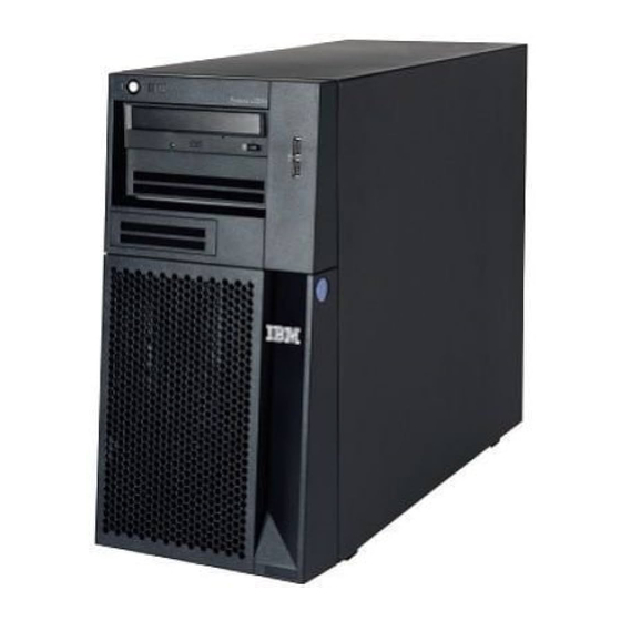
Page 8
All caution and danger statements in this documentation begin with a number. This number is used to cross reference an English caution or danger statement with translated versions of the caution or danger statement in the IBM Safety Information book.
Page 9
Statement 1: DANGER Electrical current from power, telephone, and communication cables is hazardous. To avoid a shock hazard: v Do not connect or disconnect any cables or perform installation, maintenance, or reconfiguration of this product during an electrical storm. v Connect all power cords to a properly wired and grounded electrical outlet.
Page 10
Statement 2: CAUTION: When replacing the lithium battery, use only IBM Part Number 33F8354 or an equivalent type battery recommended by the manufacturer. If your system has a module containing a lithium battery, replace it only with the same module type made by the same manufacturer.
Page 11
Statement 3: CAUTION: When laser products (such as CD-ROMs, DVD drives, fiber optic devices, or transmitters) are installed, note the following: v Do not remove the covers. Removing the covers of the laser product could result in exposure to hazardous laser radiation. There are no serviceable parts inside the device.
Page 12
Statement 4: ≥ 18 kg (39.7 lb) ≥ 32 kg (70.5 lb) ≥ 55 kg (121.2 lb) CAUTION: Use safe practices when lifting. Statement 5: CAUTION: The power control button on the device and the power switch on the power supply do not turn off the electrical current supplied to the device.
Page 13
Statement 8: CAUTION: Never remove the cover on a power supply or any part that has the following label attached. Hazardous voltage, current, and energy levels are present inside any component that has this label attached. There are no serviceable parts inside these components.
Page 14
Statement 15: CAUTION: Make sure that the rack is secured properly to avoid tipping when the server unit is extended. System x3200 Types 4362 and 4363: User’s Guide...
Safety Information This document is in PDF on the IBM System x Documentation CD. It contains translated caution and danger statements. Each caution and danger statement that appears in the documentation has a number that you can use to locate the corresponding statement in your language in the Safety Information document.
Features and specifications The following information is a summary of the features and specifications of the server. Depending on the server model, some features might not be available, or some specifications might not apply. Table 1. Features and specifications Microprocessor: Fans: Environment: ®...
IBM Enhanced Diagnostics CD The server comes with an IBM Enhanced Diagnostics CD, which you can use to diagnose problems. v IBM Director IBM Director is a workgroup-hardware-management tool that you can use to ®...
See the documentation that comes with your systems-management software for more information. To order an optional Remote Supervisor Adapter II SlimLine, contact your IBM marketing representative or authorized reseller. Reliability, availability, and serviceability Three important server design features are reliability, availability, and serviceability (RAS).
Support for the optional IBM Remote Supervisor Adapter II SlimLine v Key-lock support for physical security v Memory change messages posted to the error log v Mini-baseboard management controller (mini-BMC) (service processor) v Power management v Power-on self-test (POST)
Reduced service and support costs For more information about IBM Director, see the documentation on the IBM Director CD that comes with the server, the IBM Director Information Center at http://publib.boulder.ibm.com/infocenter/eserver/v1r2/topic/diricinfo/fgm0_main.htm, and the IBM xSeries Systems Management Web page at http://www.ibm.com/ servers/eserver/xseries/systems_management/, which presents an overview of IBM Systems Management and IBM Director.
An LED on the system board might also be lit to help isolate the error. Detailed troubleshooting information is in the Problem Determination and Service Guide on the IBM System x Documentation CD. USB connectors Connect USB devices to these connectors.
Page 23
CD-eject or DVD-eject button Press this button to release a CD from the CD drive or a DVD from the DVD drive. CD or DVD drive activity LED When this LED is lit, it indicates that the CD drive or DVD drive is in use. (Optional) External diskette-eject button Press this button to release a diskette from the diskette drive.
Rear view The following illustration shows the connectors and indicators on the rear of the server. Hot-swap power supplies Fixed power supply Power cord Serial 2 Mouse Keyboard Serial 1 Parallel AC power LED DC power LED Video USB (2) Ethernet USB (2) Remote Supervisor...
Ethernet connector Use this connector to connect the server to a network. Ethernet transmit/receive activity LED This LED is on the Ethernet connector on the rear of the server. When this LED is lit, it indicates that there is activity between the server and the network.
Turning off the server When you turn off the server and leave it connected to ac power, the server can respond to remote requests to turn on the server. To remove all power from the server, you must disconnect it from the power source. Some operating systems require an orderly shutdown before you turn off the server.
System-board internal connectors The following illustration shows the internal connectors on the system board. Rear system fan connector Microprocessor fan Serial 2 connector Wake-on-LAN Power connector (24 pin) Power connector (4 pin) Battery Drive connector (optional) Microprocessor connector SAS/SATA controller DIMM 1 connector connector DIMM 2 connector...
System-board switches and jumpers The following illustration shows the jumpers on the system board. There are no changeable switches on the system board. System rest (nopop) (JP3) Serial 2 switch (JP9) NMI button NMI button switch (SW1) Clear CMOS jumper (JP 2) Boot block jumper (JP6) mini-BMC force update jumper (JP 1) Force power on jumper(JP8)
System-board external connectors The following illustration shows the external input/output (I/O) connectors on the system board. Serial 2 Mouse Keyboard Serial 1 Parallel Video USB (2) Ethernet USB (2) Remote Supervisor Adapter II SlimLine Ethernet System x3200 Types 4362 and 4363: User’s Guide...
DASD fan error LED DIMM 4 error LED For more information about the system-board LEDs, see the Problem Determination and Service Guide on the IBM System x Documentation CD. Installation guidelines Before you install optional devices, read the following information: v Read the safety information that begins on page v, the guidelines in “Working...
When you are finished working on the server, reinstall all safety shields, guards, labels, and ground wires. v For a list of supported optional devices for the server, see http://www.ibm.com/ servers/eserver/serverproven/compat/us/. System reliability guidelines...
Working inside the server with the power on Attention: Static electricity that is released to internal server components when the server is powered-on might cause the server to halt, which could result in the loss of data. To avoid this potential problem, always use an electrostatic-discharge wrist strap or other grounding system when working inside the server with the power on.
Removing the side cover To remove the server side cover, complete the following steps: 1. Review the safety information that begins on page v and “Installation guidelines” on page 18. 2. Turn off the server and all attached devices (see “Server power features” on page 11);...
Removing the two-piece bezel When working with some devices, such as drives in bays 1 through 7, you must first remove the two-piece bezel to access the devices. Notes: v Before you remove the upper bezel, you must unlock and remove the side cover and remove the lower bezel.
Page 37
4. Carefully pull the two bezel clips on the left side of the upper bezel away from the chassis; then, rotate the upper bezel to the right side of the server to disengage the two right-side tabs from the chassis. Set the upper bezel aside. For instructions for replacing the two-piece bezel, see “Reinstalling the two-piece bezel”...
(ECC) DIMMs. These DIMMs must be compatible with the latest DDR2 667 MHz SDRAM unbuffered DIMM specification. For a list of supported optional devices for the server, see http://www.ibm.com/servers/eserver/ serverproven/compat/us/. v When you restart the server after you add or remove a DIMM, the server displays a message that the memory configuration has changed.
Page 39
The following illustration shows the dual inline memory module (DIMM) connectors and corresponding LEDs on the system board. DIMM 1 DIMM 2 DIMM 3 DIMM 4 DIMM 4 error LED DIMM 3 error LED DIMM 2 error LED DIMM 1 error LED Attention: Static electricity that is released to internal server components when the server is powered-on might cause the server to stop, which could result in the...
Page 40
4. Locate the DIMM connectors on the system board. Determine the connectors into which you will install the DIMMs. Install the DIMMs in the sequence shown in the following table. Number of DIMMs Installation sequence (connectors) 2 (interleaved configuration) 1, 3 Not supported 4 (interleaved configuration) 1, 3, 2, 4...
PCI or PCI Express adapter slot cover in the event that you later remove the device. v For a complete list of supported optional devices for the server, see http://www.ibm.com/servers/eserver/serverproven/compat/us/. Chapter 2. Installing optional devices...
Installing a CD or DVD drive EMC shield Filler panel Tape drive Drive retainer clip To install a CD or DVD drive, complete the following steps: 1. Read the safety information that begins on page v and “Installation guidelines” on page 18. 2.
Page 43
Note: If you are installing a drive that contains a laser, observe the following safety precaution. Statement 3: CAUTION: When laser products (such as CD-ROMs, DVD drives, fiber optic devices, or transmitters) are installed, note the following: v Do not remove the covers. Removing the covers of the laser product could result in exposure to hazardous laser radiation.
9. If you are installing a 5.25 in. drive in bay 2, push the drive into the bay. If you are installing a 3.5 in. drive in bay 2, you must attach the 5.25 in. conversion kit to the 3.5 in. drive. Note: An optional diskette drive can be installed in bay 3.
5. Use a screwdriver to pry the filler panel and EMC shield away from the server. 6. Touch the static-protective package that contains the drive to any unpainted metal surface on the server; then, remove the drive from the package and place it on a static-protective surface.
Page 46
Note: If the server is configured for RAID operation using an optional ServeRAID adapter, you might have to reconfigure your disk arrays after installing hard disk drives. See the ServeRAID documentation on the IBM ServeRAID Support CD for additional information about RAID operation and complete instructions for using ServeRAID Manager.
6. If you are installing additional hot-swap hard disk drives, do so now. If you have other devices to install or remove, do so now; otherwise, go to “Completing the installation” on page 42. IDs for hot-swap hard disk drives The hot-swap-drive backplane controls the IDs for the internal hot-swap drive bays.
Page 48
To install a simple-swap hard disk drive, complete the following steps: 1. Read the safety information that begins on page v and “Installation guidelines” on page 18. 2. Turn off the server and peripheral devices and disconnect all external cables and power cords.
Power and signal cables for internal drives The server uses cables to connect parallel IDE, simple-swap SATA, and SAS devices to the power supply and to the system board. (See “System-board internal connectors” on page 14 for the location of system-board connectors.) Review the following information before you connect power and signal cables to internal drives: v The drives that are preinstalled in the server come with power and signal cables attached.
3.3 V keyed adapters. Universal adapters are supported in slots 3, 4, and 5 if they are universally keyed. v An optional IBM Remote Supervisor Adapter II can be installed only in its dedicated connector on the system board. See “System-board internal connectors”...
Page 51
Expansion-slot cover Adapter Left side Front adapter retention bracket Right side To install an adapter, complete the following steps: 1. Read the safety information that begins on page v and “Installation guidelines” on page 18. 2. Turn off the server and peripheral devices and disconnect all external cables and power cords;...
Page 52
7. Touch the static-protective package that contains the adapter to any unpainted metal surface on the server. Then, remove the adapter from the static-protective package. Avoid touching the components and gold-edge connectors on the adapter. 8. If you are installing a full-length adapter, remove the blue adapter guide (if any) from the end of the adapter.
Installing a hot-swap power supply The following notes describe the type of power supply that the server supports and other information that you must consider when you install a power supply: v The type and number of power supplies vary by server model. The server comes with at least one power supply.
Page 54
1. Review the safety information that begins on page v and “Installation guidelines” on page 18. 2. Turn off the server and attached devices; then, disconnect all power cords and external cables. 3. Remove the side cover (see “Removing the side cover” on page 21). 4.
Installing a security rope clip To help prevent hardware theft, you can add a security rope clip and cable to the server. After you add the security cable, make sure that it does not interfere with other cables that are connected to the server. Before you begin, obtain the following items: v A flat-blade screwdriver v An adjustable wrench...
the cable cannot be removed. Fasten the cable ends together with a lock. After you add the security cable, make sure that it does not interfere with other cables that are connected to the server. If you have other devices to install or remove, do so now; otherwise, go to “Completing the installation.”...
Page 57
2. Install the lower bezel on the front of the server chassis. a. Insert the two bottom tabs on the lower bezel into the matching holes in the front of the chassis. b. Tilt the top of the lower bezel into position on the chassis until the lower bezel locks securely into place.
Reinstalling the side cover If you removed the bezel, reinstall it before you reinstall the side cover. See “Reinstalling the two-piece bezel” on page 42. Note: The rear adapter-retention bracket rests against the server side cover. You might find it easier to lay the server on its side to replace the side cover. Cover-release latch Key lock...
Connecting the cables Attention: To prevent damage to equipment, connect the power cords last. If the server cables and connector panel have color-coded connectors, match the color of each cable end with the color of the connector. For example, match a blue cable end to a blue connector on the panel, a red cable end with a red connector, and so on.
An optional Tower-to-Rack Kit is needed to convert the server from a tower model to a rack model. You can then install the server in a rack cabinet. To order a Tower-to-Rack Kit for the server, contact your IBM marketing representative or authorized reseller.
For information about using this utility program, see “Using the Configuration/Setup Utility program” on page 47. v IBM ServerGuide Setup and Installation CD The ServerGuide program provides software-setup tools and installation tools that are designed for the server. Use this CD during the installation of the server to configure basic hardware features, such as an integrated SAS/SATA controller with RAID capabilities, and to simplify the installation of the operating system.
few seconds. You must press F1 quickly.) If you have set both a power-on password and an administrator password, you must type the administrator password to access the full Configuration/Setup Utility menu. If you do not type the administrator password a limited Configuration/Setup Utility menu is available.
Page 63
Select this choice to enable and configure serial remote video and keyboard redirection. – Internal Floppy Disk Select this choice to disable or enable the internal diskette drive. – Mouse Select this choice to specify whether the mouse is installed or not installed. –...
Page 64
You can enable a virus-detecting test that checks for changes in the boot record when the server starts. – Startup Sequence Options Select this choice to view the Startup Sequence Optionsmenu. The startup sequence specifies the order in which the server checks devices to find a boot record.
ServerGuide program. You can download a free image of the ServerGuide Setup and Installation CD, or you can purchase the CD. To download the image, go to the IBM ServerGuide Web page at http://www.ibm.com/pc/qtechinfo/MIGR-4ZKPPT.html. To purchase the latest ServerGuide Setup and Installation CD, go to the ServerGuide fulfillment Web site at http://www.ibm.com/servers/eserver/xseries/systems_management/serverguide/...
When you use the ServerGuide Setup and Installation CD, you do not need setup diskettes. You can use the CD to configure any supported IBM server model. The setup program provides a list of tasks that are required to set up the server model.
ServerGuide program to install your operating system, complete the following steps to download the latest operating-system installation instructions from the IBM Web site: Note: Changes are made periodically to the IBM Web site. The actual procedure might vary slightly from what is described in this document. 1. Go to http://www.ibm.com/servers/eserver/support/xseries/index.html/ 2.
Broadcom NetXtreme Gigabit Ethernet Software CD that comes with the server. To find updated information about configuring the controller, complete the following steps. Note: Changes are made periodically to the IBM Web site. The actual procedure might vary slightly from what is described in this document. 1. Go to http://www.ibm.com/servers/eserver/support/xseries/index.html/ 2.
Use this option to create an integrated mirror enhanced array of three to eight disks, including an optional hot spare. – Integrated Striping (IS) (also known as RAID 0) Use this option to create an integrated striping array of two to eight disks. All data on the array disk will be deleted.
Page 70
1. From the list of adapters, select the controller (channel) for the drives that you want to mirror. 2. Select RAID Properties. 3. Select the type of array that you want to create. 4. Use the arrow keys to highlight the first drive in the pair; then, press the Minus (-) or Plus (+) key to change the mirror value to Primary.
Web sites. The materials at those Web sites are not part of the materials for this IBM product, and use of those Web sites is at your own risk. IBM may use or distribute any of the information you supply in any way it believes appropriate without incurring any obligation to you.
Maximum internal hard disk drive capacities assume the replacement of any standard hard disk drives and population of all hard disk drive bays with the largest currently supported drives available from IBM. Maximum memory may require replacement of the standard memory with an optional memory module.
IBM makes no representations or warranties with respect to non-IBM products. Support (if any) for the non-IBM products is provided by the third party, not IBM. Some software may differ from its retail version (if available), and may not include user manuals or all program functionality.
United States, go to http://www.ibm.com/ibm/environment/ products/batteryrecycle.shtml or contact your local waste disposal facility. In the United States, IBM has established a return process for reuse, recycling, or proper disposal of used IBM sealed lead acid, nickel cadmium, nickel metal hydride, and battery packs from IBM equipment.
Properly shielded and grounded cables and connectors must be used in order to meet FCC emission limits. IBM is not responsible for any radio or television interference caused by using other than recommended cables and connectors or by unauthorized changes or modifications to this equipment.
IBM cannot accept responsibility for any failure to satisfy the protection requirements resulting from a nonrecommended modification of the product, including the fitting of non-IBM option cards. This product has been tested and found to comply with the limits for Class A Information Technology Equipment according to CISPR 22/European Standard EN 55022.
Page 78
39 Agent 53 safety 39 environment 3 Ethernet activity LED 11 connector 11 IBM Configuration/Setup Utility program high performance modes 54 menu choices 48 integrated on system board 54 starting 47 link status LED 11 using 47 modes 54...
Page 79
optional device (continued) static-sensitive 20 keyboard connector 10 optional devices connectors 10 options adapters 36, 37 connectors 17 AC power 11 drives 27 LEDs installing 18 CD drive activity 9 memory modules 24 diskette drive activity 9 order of installation DVD drive activity 9 hard disk drives 33 Ethernet link status 11...
Page 80
51 serviceability features 5 setup Web site advanced 50 compatible options 19, 24 with ServerGuide 52 IBM eServer and System x3200 products 1 simple-swap drives 33 IBM support 2 size 3 ServerGuide 51 specifications 3 ServerProven list 19, 24, 36...
Page 81
Web site (continued) Update Xpress program 7 weight 3 Index...
Page 82
System x3200 Types 4362 and 4363: User’s Guide...
Page 84
Part Number: 42D2453 Printed in USA (1P) P/N: 42D2453...