Mitsubishi Electric Q172DCPU User Manual
Motion controller
q series
Hide thumbs
Also See for Q172DCPU:
- Programming manual (174 pages) ,
- Migration manual (52 pages) ,
- Programming manual (624 pages)
Table of Contents
Advertisement
Advertisement
Table of Contents
Troubleshooting

Related Manuals for Mitsubishi Electric Q172DCPU


Summary of Contents for Mitsubishi Electric Q172DCPU
- Page 1 MOTION CONTROLLERS Q173DCPU Q172DCPU User's Manual...
-
Page 2: Safety Precautions
SAFETY PRECAUTIONS (Please read these instructions before using this equipment.) Before using this product, please read this manual and the relevant manuals introduced in this manual carefully and pay full attention to safety to handle the product correctly. These precautions apply only to this product. Refer to the Users manual of the QCPU module to use for a description of the PLC system safety precautions. - Page 3 For Safe Operations 1. Prevention of electric shocks DANGER Never open the front case or terminal covers while the power is ON or the unit is running, as this may lead to electric shocks. Never run the unit with the front case or terminal cover removed. The high voltage terminal and charged sections will be exposed and may lead to electric shocks.
- Page 4 3. For injury prevention CAUTION Do not apply a voltage other than that specified in the instruction manual on any terminal. Doing so may lead to destruction or damage. Do not mistake the terminal connections, as this may lead to destruction or damage. Do not mistake the polarity ( + / - ), as this may lead to destruction or damage.
- Page 5 CAUTION The dynamic brakes must be used only on errors that cause the forced stop, emergency stop, or servo OFF. These brakes must not be used for normal braking. The brakes (electromagnetic brakes) assembled into the servomotor are for holding applications, and must not be used for normal braking.
- Page 6 CAUTION Use the program commands for the program with the conditions specified in the instruction manual. Set the sequence function program capacity setting, device capacity, latch validity range, I/O assignment setting, and validity of continuous operation during error detection to values that are compatible with the system application.
- Page 7 CAUTION The Motion controller, servo amplifier and servomotor are precision machines, so do not drop or apply strong impacts on them. Securely fix the Motion controller, servo amplifier and servomotor to the machine according to the instruction manual. If the fixing is insufficient, these may come off during operation. Always install the servomotor with reduction gears in the designated direction.
- Page 8 (4) Wiring CAUTION Correctly and securely wire the wires. Reconfirm the connections for mistakes and the terminal screws for tightness after wiring. Failing to do so may lead to run away of the servomotor. After wiring, install the protective covers such as the terminal covers to the original positions. Do not install a phase advancing capacitor, surge absorber or radio noise filter (option FR-BIF) on the output side of the servo amplifier.
- Page 9 (6) Usage methods CAUTION Immediately turn OFF the power if smoke, abnormal sounds or odors are emitted from the Motion controller, servo amplifier or servomotor. Always execute a test operation before starting actual operations after the program or parameters have been changed or after maintenance and inspection. Do not attempt to disassemble and repair the units excluding a qualified technician whom our company recognized.
- Page 10 (7) Corrective actions for errors CAUTION If an error occurs in the self diagnosis of the Motion controller or servo amplifier, confirm the check details according to the instruction manual, and restore the operation. If a dangerous state is predicted in case of a power failure or product failure, use a servomotor with electromagnetic brakes or install a brake mechanism externally.
- Page 11 CAUTION When replacing the Motion controller or servo amplifier, always set the new module settings correctly. When the Motion controller or absolute value motor has been replaced, carry out a home position return operation using one of the following methods, otherwise position displacement could occur. 1) After writing the servo data to the Motion controller using programming software, switch on the power again, then perform a home position return operation.
-
Page 12: Revisions
This manual confers no industrial property rights or any rights of any other kind, nor does it confer any patent licenses. Mitsubishi Electric Corporation cannot be held responsible for any problems involving industrial property rights which may occur as a result of using the contents noted in this manual. -
Page 13: Table Of Contents
2.1.1 Q173DCPU System overall configuration ..................2- 3 2.1.2 Q172DCPU System overall configuration ..................2- 5 2.1.3 Function explanation of the Q173DCPU/Q172DCPU Motion CPU modules ......... 2- 7 2.1.4 Restrictions on Motion systems......................2- 8 2.2 System Configuration Equipment......................2-11 2.3 General Specifications .......................... - Page 14 4. INSTALLATION AND WIRING 4- 1 to 4-26 4.1 Module Installation ........................... 4- 1 4.1.1 Instructions for handling ........................4- 1 4.1.2 Instructions for mounting the base unit .................... 4- 3 4.1.3 Installation and removal of module....................4- 6 4.1.4 Instructions for mounting of the battery holder unit................4- 9 4.2 Connection and disconnection of Cable....................
- Page 15 APPENDIX 2 Exterior Dimensions ......................App- 8 APPENDIX 2.1 CPU module .........................App- 8 APPENDIX 2.2 Servo external signals interface module (Q172DLX)..........App- 9 APPENDIX 2.3 Synchronous encoder interface module (Q172DEX)..........App- 9 APPENDIX 2.4 Manual pulse generator interface module (Q173DPX)..........App-10 APPENDIX 2.5 Power supply module (Q61P-A1, Q61P-A2, Q61P, Q62P, Q63P, Q64P)....App-11 APPENDIX 2.6 Battery holder unit (Q170DBATC) ................App-12 APPENDIX 2.7 Connector ........................App-13 APPENDIX 2.8 Manual pulse generator (MR-HDP01) .................App-16...
-
Page 16: About Manuals
This manual explains the Multiple CPU system configuration, performance specifications, common IB-0300134 (1XB928) parameters, auxiliary/applied functions, error lists and others. (Optional) Q173DCPU/Q172DCPU Motion controller (SV13/SV22) Programming Manual (Motion SFC) IB-0300135 This manual explains the functions, programming, debugging, error lists and others for Motion SFC. (1XB929) (Optional) - Page 17 (2) PLC Manual Number Manual Name (Model Code) QCPU User's Manual (Hardware Design, Maintenance and Inspection) This manual explains the specifications of the QCPU modules, power supply modules, base modules, SH-080483ENG (13JR73) extension cables, memory card battery and others. (Optional) QCPU User's Manual (Function Explanation, Program Fundamentals) This manual explains the functions, programming methods and devices and others to create programs SH-080484ENG...
-
Page 18: Overview
1. OVERVIEW 1.1 Overview This User's Manual describes the hardware specifications and handling methods of the Motion Controller's Model Q173DCPU/Q172DCPU for the Q series PLC Multiple CPU system. The Manual also describes those items related to the specifications of the option module for the Motion controller, Manual pulse generator, Synchronous encoder and cables. - Page 19 Operation method for MT Developer Help of each software • Multiple CPU system configuration • Performance specification Q173DCPU/Q172DCPU Motion controller • Design method for common parameter Programming Manual (COMMON) • Auxiliary and applied functions (common) • Design method for Motion SFC program...
-
Page 20: Differences Between Q173Dcpu/Q172Dcpu And Q173Hcpu/Q172Hcpu
1 OVERVIEW 1.2 Differences between Q173DCPU/Q172DCPU and Q173HCPU/Q172HCPU Items Q173DCPU Q172DCPU Q173HCPU Q173HCPU 0.44ms/ 1 to 3 axes 0.44ms/ 1 to 6 axes 0.44ms/ 1 to 6 axes 0.88ms/ 4 to 10 axes 0.44ms/ 1 to 3 axes SV13 0.88ms/ 7 to 18 axes 0.88ms/ 7 to 8 axes... - Page 21 1 OVERVIEW MEMO 1 - 4...
-
Page 22: System Configuration
2 SYSTEM CONFIGURATION 2. SYSTEM CONFIGURATION This section describes the Q173DCPU/Q172DCPU system configuration, precautions on use of system and configured equipments. 2.1 Motion System Configuration (1) Equipment configuration in Q173DCPU/Q172DCPU system Extension of the Q series module (Note-2) Power supply module/... - Page 23 2 SYSTEM CONFIGURATION (2) Peripheral device configuration for the Q173DCPU/Q172DCPU The following (a)(b) can be used. (a) USB configuration (b) RS-232 configuration PLC CPU module PLC CPU module (QnUD(H)CPU) ( QnUD(H)CPU ) RS-232 communication cable USB cable (QC30R2) Personal computer...
-
Page 24: Q173Dcpu System Overall Configuration
2 SYSTEM CONFIGURATION 2.1.1 Q173DCPU System overall configuration Motion CPU control module PLC CPU/ Motion CPU Main base unit (Q3 DB) QnUD(H) Q173D QI60 Q6 AD Q172D Q172D Q173D Q61P Q6 DA I/O module/ Intelligent function module 100/200VAC Manual pulse generator 3/module (MR-HDP01) (Up to 1 module) - Page 25 2 SYSTEM CONFIGURATION CAUTION Construct a safety circuit externally of the Motion controller or servo amplifier if the abnormal operation of the Motion controller or servo amplifier differ from the safety directive operation in the system. The ratings and characteristics of the parts (other than Motion controller, servo amplifier and servomotor) used in a system must be compatible with the Motion controller, servo amplifier and servomotor.
-
Page 26: Q172Dcpu System Overall Configuration
2 SYSTEM CONFIGURATION 2.1.2 Q172DCPU System overall configuration Motion CPU control module PLC CPU/ Motion CPU Main base unit (Q3 DB) QnUD(H) Q172D QI60 Q6 AD Q172D Q172D Q173D Q61P Q6 DA I/O module / Intelligent function module 100/200VAC Manual pulse generator... - Page 27 2 SYSTEM CONFIGURATION CAUTION Construct a safety circuit externally of the Motion controller or servo amplifier if the abnormal operation of the Motion controller or servo amplifier differ from the safety directive operation in the system. The ratings and characteristics of the parts (other than Motion controller, servo amplifier and servomotor) used in a system must be compatible with the Motion controller, servo amplifier and servomotor.
-
Page 28: Function Explanation Of The Q173Dcpu/Q172Dcpu Motion Cpu Modules
Q172DCPU. (5) Motion modules (Q172DLX/Q172DEX/Q173DPX) are controlled with the Q173DCPU/Q172DCPU, and the signals such as stroke limit signals connected to Motion modules and synchronous encoder are used as motion control. (6) PLC I/O modules can be controlled with the Q173DCPU/Q172DCPU. -
Page 29: Restrictions On Motion Systems
Multiple CPU settings. (b) Only Multiple CPU high speed main base unit (Q38DB/Q312DB) can be used. (c) The combination of Q173DCPU/Q172DCPU and Q173HCPU(-T)/ Q172HCPU(-T)/Q173CPUN(-T)/Q172CPUN(-T) cannot be used. (d) Up to four modules of PLC CPU modules (Q03UDCPU/Q04UDHCPU/ Q06UDHCPU/Motion CPU modules can be installed from the CPU slot (the slot on the right side of power supply module) to slot 2 of the main base unit. - Page 30 2 SYSTEM CONFIGURATION (2) Motion modules (Note-1) (a) Installation position of Q172DEX is only the main base unit. It cannot be used on the extension base unit. (b) Q172DLX/Q173DPX can be installed on any of the main base unit/ extension base unit. (Note-1) (c) Q172DLX/Q172DEX /Q173DPX cannot be installed in CPU slot and I/O...
- Page 31 2 SYSTEM CONFIGURATION (3) Other restrictions (a) Motion CPU module cannot be set as the control CPU of intelligent function module (except some modules) or Graphic Operation Terminal(GOT). (b) Be sure to use the external battery. (c) There are following methods to execute the forced stop input. •...
-
Page 32: System Configuration Equipment
Q173DCPU 1.25 (Attachment battery holder unit and battery (Q6BAT)) Motion CPU module Up to 8 axes control, Operation cycle 0.44[ms] or more Q172DCPU 1.25 (Attachment battery holder unit and battery (Q6BAT)) Servo external Servo external signal input 8 axes signals Q172DLX 0.06... - Page 33 2 SYSTEM CONFIGURATION Table of Motion controller related module(continued) Current (Note-1) Part name Model name Description consumption Remark 5VDC[A] Q172DEX side connector Connector set for Connector :10120-3000PE serial absolute Connector case : 10320-52F0-008 Q170ENCCNS —— synchronous Q170ENC side connector encoder cable Plug : MS3106B22-14S Cable clump : MS3057-12A...
- Page 34 Table of Motion controller related module(continued) Current (Note-1) Part name Model name Description consumption Remark 5VDC[A] • Q173DCPU/Q172DCPU MR-J3- B • MR-J3- B MR-J3- B MR-J3BUS M —— • Standard code for inside panel • 0.15m(0.49ft.), 0.3m(0.98ft.), 0.5m(1.64ft.), 1m(3,28ft.), 3m(9.84ft.) • Q173DCPU/Q172DCPU MR-J3- B •...
- Page 35 2 SYSTEM CONFIGURATION (2) PLC module which can be control by Motion CPU Current consumption Part name Model name Description Remark (Note-1) 5VDC[A] QX10 100-120VAC, 7-8mA, 16 points, Terminal block 0.05 QX40 24VDC/4mA, Positive common, 16 points, Terminal block 0.05 0.075 (Note-2) QX41...
- Page 36 2 SYSTEM CONFIGURATION Current consumption Part name Model name Description Remark (Note-1) 5VDC[A] 2ch, A/D conversion, (Note-2) Q62AD-DGH 0.33 Current input (Channel-isolated • High resolution) Q64AD 4ch, A/D conversion, Voltage • Current input 0.63 4ch, A/D conversion, (Note-2) Q64AD-GH 0.89 Voltage •...
- Page 37 MR-J3- B-RJ006 Battery MR-J3BAT Back-up for the absolute position detection (4) Software packages (a) Operating system software Software package Application Q173DCPU Q172DCPU For conveyor assembly SV13 SW8DNC-SV13QB SW8DNC-SV13QD For automatic machinery SV22 SW8DNC-SV22QA SW8DNC-SV22QC (b) Motion controller programming software Part name...
- Page 38 2 SYSTEM CONFIGURATION (6) Related software packages (a) PLC software package Model name Software package GX Developer SW8D5C-GPPW-E (b) Servo set up software package Model name Software package MR Configurator MRZJW3-SETUP221E POINTS (1) When the operation of Windows is not unclear in the operation of this software, refer to the manual of Windows or guide-book from the other supplier.
-
Page 39: General Specifications
2 SYSTEM CONFIGURATION 2.3 General Specifications General specifications of Q173DCPU/Q172DCPU module are shown below. Item Specification Operating ambient temperature 0 to 55°C (32 to 131°F) (Note-3) Storage ambient temperature -25 to 75°C (-13 to 167°F) Operating ambient humidity 5 to 95% RH... -
Page 40: Specifications Of Equipment And Settings
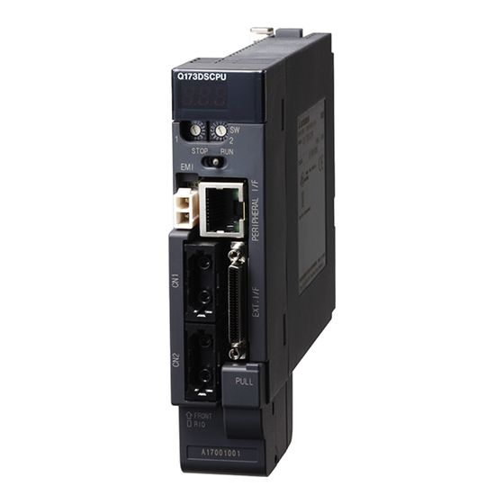
2 SYSTEM CONFIGURATION 2.4 Specifications of Equipment and Settings 2.4.1 Name of parts for CPU module This section explains the names and setting of the module. (1) Q173DCPU/Q172DCPU Front face of Q172DCPU Front face of Q173DCPU Q172DCPU Q173DCPU STOP RUN... - Page 41 2 SYSTEM CONFIGURATION Name Application 1) 7-segment LED • Indicates the operating status and error information. Rotary function select 1 switch • Set the operation mode. (SW1) (Normal operation mode, Installation mode, Mode operated by ROM, etc) • Each switch setting is 0 to F. Rotary function select 2 switch (Shipped from the factory in SW1 "A", SW2 "0"...
- Page 42 System setting error of the Motion CPU " AL" flashes 3 times Refer to the "Q173DCPU/Q172DCPU System setting error Motion controller Programming Manual Steady " L01" display (COMMON)" for details.
- Page 43 7-segment LED Remark " AL" flashes 3 times Setting error of the Multiple CPU system Steady " A1" display Refer to the "Q173DCPU/Q172DCPU Self diagnostic error Motion controller Programming Manual 4-digits error code is (COMMON)" for details. displayed in two sequential flashes of 2-digits each.
- Page 44 2 SYSTEM CONFIGURATION (4) Operation mode (a) Rotary switch setting and operation mode (Note) Rotary switch setting Operation mode Any setting (Except C) Installation mode Mode operated by RAM Mode operated by ROM (Note) Any setting SRAM clear (Note) : The programs, parameters, absolute position data, and latch data built-in Motion CPU module are cleared.
- Page 45 2 SYSTEM CONFIGURATION (5) Basic specifications of Q173DCPU/Q172DCPU (a) Module specifications Item Q173DCPU Q172DCPU Internal current consumption (5VDC) [A] 1.25 1.14 Mass [kg] 0.33 0.33 Exterior dimensions [mm(inch)] 98 (3.85)(H) 27.4 (1.08)(W) 119.3 (4.69)(D) (6) SV13/SV22 Motion control specifications/performance specifications...
- Page 46 2 SYSTEM CONFIGURATION Motion control specifications (continued) Item Q173DCPU Q172DCPU Made compatible by setting battery to servo amplifier. Absolute position system (Possible to select the absolute data method or incremental method for each axis) Number of SSCNET 2 systems 1 system...
- Page 47 2 SYSTEM CONFIGURATION (b) Motion SFC performance specifications Item Q173DCPU/Q172DCPU Code total (Motion SFC chart + Operation control 543k bytes Motion SFC program capacity + Transition) Text total 484k bytes (Operation control + Transition) Number of Motion SFC programs 256 (No.0 to 255)
-
Page 48: Power Supply Module
2 SYSTEM CONFIGURATION 2.4.2 Power supply module (1) Table of the power supply module specifications This section describes the power supply modules specifications. Item Q61P-A1 Q61P-A2 Q61P Q62P Base loading position Q series power supply module loading slot Applicable base unit Q38DB, Q312DB, Q63B, Q65B, Q68B, Q612B 100 to 120VAC 200 to 240VAC... - Page 49 2 SYSTEM CONFIGURATION The power supply module specifications (continued) Item Q63P Q64P Base loading position Q series power supply module loading slot Applicable base unit Q38DB, Q312DB, Q63B, Q65B, Q68B, Q612B 24VDC (+30%/-35%) 100 to 120VAC/200 to 240VAC (+10%/-15%) Input power supply (15.6 to 31.2VDC) (85 to 132VAC/170 to 264VAC) Input frequency...
- Page 50 2 SYSTEM CONFIGURATION POINTS (Note-1) : Overcurrent protection The overcurrent protection device shuts off the 5V, 24VDC circuit and stops the system if the current flowing in the circuit exceeds the specified value. The LED of the power supply module is turned off or lights up in dim green when voltage is lowered.
- Page 51 2 SYSTEM CONFIGURATION POINTS (Note-3) : Allowable momentary power failure period (1) For AC input power supply (a) An instantaneous power failure lasting less than 20ms will cause AC down to be detected, but operation will continue. (b) An instantaneous power failure lasting in excess of 20ms may cause the operation to continue or initial start to take place depending on the power supply load.
- Page 52 2 SYSTEM CONFIGURATION (2) Names of Parts and Setting This section describes the names of the parts of each power module. • Q61P-A1 (100 to 120VAC input, 5VDC 6A output) • Q61P-A2 (200 to 240VAC input, 5VDC 6A output) • Q61P (100 to 240VAC input, 5VDC 6A output) •...
- Page 53 2 SYSTEM CONFIGURATION Name Application ON (green): Normal (5VDC output, momentary power failure within 20ms) : • AC power supply is ON, however, the power supply module is out of order. AC input (5VDC error, internal circuit failure, blown fuse) power supply •...
- Page 54 2 SYSTEM CONFIGURATION POINTS (1) The Q61P-A1 is dedicated for inputting a voltage of 100VAC. Do not input a voltage of 200VAC into it or trouble may occur on the Q61P-A1. Power Supply power voltage module type 100VAC 200VAC Power supply module causes Q61P-A1 Operates normally.
- Page 55 2 SYSTEM CONFIGURATION (3) Selection of the power supply module The power supply module is selected according to the total of current consumption of the I/O modules, intelligent function module, and peripheral devices supplied by its power module. (Select the power supply module in consideration of the current consumption of the peripheral device connected to the Q170ENC, MR-HDP01 etc.) 5VDC internal current consumption of shared equipments with PLC might be...
-
Page 56: Base Unit And Extension Cable
2 SYSTEM CONFIGURATION 2.4.3. Base unit and extension cable This section describes the specifications of the extension cables for the base units (Main base unit or extension base unit) used in the system, and the specification standards of the extension base unit. 5VDC internal current consumption of base unit might be changed. - Page 57 2 SYSTEM CONFIGURATION (2) Table of the extension cable specifications The list below describes the specifications of the extension cables which can be used for the PLC CPU system. Type QC05B QC06B QC12B QC30B QC50B QC100B Item Cable length[m(ft.)] 0.45(1.48) 0.6(1.97) 1.2(3.94) 3.0(9.84)
- Page 58 (Note-1) : When the number of modules to be installed is 32 points. (Note-2) : When the PX/PY No. does not match the PLC I/O No. Refer to the Q173DCPU/Q172DCPU Motion Controller Programming Manual (COMMON) about the I/O allocation setting method.
-
Page 59: Q172Dlx Servo External Signals Interface Module
2 SYSTEM CONFIGURATION 2.4.4 Q172DLX Servo external signals interface module Q172DLX receives external signals (servo external signals) required for positioning control. (1) Q172DLX name of parts Q172DLX CTRL Q172DLX Name Application Hook used to fix the module to the base unit. Module fixing hook (Single-motion installation) Display the servo external input status from the external... - Page 60 2 SYSTEM CONFIGURATION (2) Performance specifications (a) Module specifications Item Specifications Number of I/O occupying points 32 points(I/O allocation: Intelligent, 32 points) Internal current consumption(5VDC) [A] 0.06 98(H) 27.4(W) 90(D) Exterior dimensions [mm(inch)] (3.86(H) 1.08(W) 3.54(D) ) Mass [kg] 0.15 (b) Input Item Specifications...
- Page 61 2 SYSTEM CONFIGURATION (3) Connection of servo external signals interface module (a) Servo external signals There are the following servo external signals. (Upper stroke limit is limit value of address increase direction/lower stroke limit is limit value of an address decrease direction.) The Q172DLX is assigned a set of input No.s per axis.
- Page 62 2 SYSTEM CONFIGURATION (b) The pin layout of the CTRL connector Use the CTRL connector at the Q172DLX module front to connect the servo external signals. The following pin layout of the Q172DLX CTRL connector viewed from the front. The pin layout and connection description of the CTRL connector are described below.
- Page 63 2 SYSTEM CONFIGURATION (4) Interface between CTRL connector and servo external signal Input or CTRL Signal name Wiring example Internal circuit Specification Description connector Output FLS1 Supply voltage FLS2 12 to 24 VDC (10.2 to 26.4 VDC, FLS3 Upper stroke stabilized power FLS4 5.6k...
-
Page 64: Q172Dex Synchronous Encoder Interface Module
2 SYSTEM CONFIGURATION 2.4.5 Q172DEX Synchronous encoder interface module Q172DEX receive external signals required for serial absolute synchronous encoder. The installation position of Q172DEX is only main base. (1) Q172DEX name of parts Q172DEX SY.ENC TREN SY.ENC1 SY.ENC2 Q172DEX Name Application Hook used to fix the module to the base unit. - Page 65 2 SYSTEM CONFIGURATION POINT (1) Mode judging LED of the serial absolute synchronous encoder signal turns ON at the normal connection (first switching to virtual mode). (2) Mode judging LED of the tracking enable signal turns ON at the following conditions.
- Page 66 2 SYSTEM CONFIGURATION (c) Serial absolute synchronous encoder input Item Specifications Applicable signal types Differential-output type : (SN75C1168 or equivalent) Transmission method Serial communications Synchronous method Counter-clock-wise (viewed from end of shaft) Communication speed 2.5Mbps Applicable types Q170ENC Position detection method Absolute (ABS) method Resolution 262144PLS/rev (18bit)
- Page 67 Synchronous encoder Q173DCPU Up to 12 modules ( Q172DEX: Up to 6 modules ) Q172DCPU Up to 8 modules ( Q172DEX: Up to 4 modules ) • Tracking enable signal Tracking enable signal of Q172DEX is used as a high-speed reading function.
- Page 68 2 SYSTEM CONFIGURATION (4) Connection of synchronous encoder interface module. (a) Connection with serial absolute synchronous encoder (Q170ENC) Use the SY.ENC connector at the Q172DEX module front to connect the serial absolute synchronous encoder (Q170ENC). When tracking enable signal is not used, use the Q170ENCCBL M encoder cable between the serial absolute synchronous encoder (Q170ENC) and SY.ENC connector.
- Page 69 2 SYSTEM CONFIGURATION (5) Interface between SY.ENC connector and external equipment Signal Pin No. Input or Wiring example Internal circuit Specification Description SY.ENC connector name Output Transmission method: Serial serial communications absolute Position detection synchronous method: absolute encoder 10 18 19 20 5VDC 1 2 3 11 12 Battery...
- Page 70 2 SYSTEM CONFIGURATION (6) Details of encoder cable connections (Note-1) (a) When not using tracking enable signal Synchronous encoder side connector(plug) SY.ENC side connector 10120-3000PE (connector) MS3106B22-14S(cable clump) 10320-52F0-008(connector case) SDplate :Twisted pair cable Q170ENCCBL2M to Q170ENCCBL50M(50m (164.04ft.) or less) (Note-1), (Note-2) (b) When using tracking enable signal Synchronous encoder side connector(plug)
- Page 71 2 SYSTEM CONFIGURATION (7) Connection of the battery This section describes the battery specifications, handling precautions and installation of the Q172DEX. (a) Specifications The specifications of the battery for memory back-up are shown in the table below. Battery Specifications Model name A6BAT/MR-BAT Item Manganese dioxide lithium primary battery...
- Page 72 2 SYSTEM CONFIGURATION (c) Battery life (Note-1) Battery life (Total power failure time) [h] Actual service value Guaranteed value Guaranteed value Module type Battery type (Note-5) Power-on time Backup time (Note-3) (Note-4) (Note-2) ratio (Reference value) after alarm (MIN) (75°C (167°F)) (TYP) (40°C (104°F)) (TYP) (25°C (77°F)) 3000...
-
Page 73: Q173Dpx Manual Pulse Generator Interface Module
2 SYSTEM CONFIGURATION 2.4.6 Q173DPX Manual pulse generator interface module Q173DPX receive external signals required for Manual pulse generator and Incremental synchronous encoder (Voltage-output/Open collector type/Differential- output type). (1) Q173DPX name of parts Q173DPX PLS.A PLS.B TREN PULSER Q173DPX Name Application Hook used to fix the module to the base unit. - Page 74 2 SYSTEM CONFIGURATION Name Application Detection setting of TREN1 signal Dip switch 1 TREN is detected at leading edge of TREN signal. Dip switch 2 TREN is detected at trailing (Note-1) Dip switches edge of TREN signal. Detection setting of TREN2 signal Dip switch 3 TREN is detected at leading edge of TREN signal.
- Page 75 2 SYSTEM CONFIGURATION (2) Performance specifications (a) Module specifications Item Specifications Number of I/O occupying points 32 points(I/O allocation: Intelligent, 32 points) Internal current consumption(5VDC)[A] 0.38 98(H) 27.4(W) 90(D) Exterior dimensions [mm(inch)] (3.86(H) 1.08(W) 3.54(D) ) Mass [kg] 0.15 (b) Tracking enable signal input Item Specifications Number of input points...
- Page 76 In addition the usable numbers of manual pulse generator which can be used with each CPU modules are up to 3 modules. Motion CPU module Manual pulse generator Q173DCPU Up to 3 modules ( Up to 1 module ) Q172DCPU 2 - 55...
- Page 77 Up to 12 modules Q173DCPU ( Q173DPX: Up to 4 modules ) Up to 8 modules Q172DCPU ( Q173DPX: Up to 3 modules ) • Tracking enable signal Tracking enable signal of Q173DPX is used to start the input from incremental synchronous encoders.
- Page 78 2 SYSTEM CONFIGURATION (5) Connection of manual pulse generator interface module (a) The pin layout of the PULSER connector Use the PULSER connector at the Q173DPX module front to connect the manual pulse signals, incremental synchronous encoder signals. The following pin layout of the Q173DPX PULSER connector viewed from the front.
- Page 79 2 SYSTEM CONFIGURATION (b) Interface between PULSER connector and manual pulse generator (Differential output type)/Incremental synchronous encoder Interface between Manual pulse generator (Differential output type)/ Incremental synchronous encoder Pin No. PULSER connector Input or Signal name Voltage-Output Wiring example Internal circuit Specification Description Output...
- Page 80 2 SYSTEM CONFIGURATION (c) Interface between PULSER connector and manual pulse generator (Voltage output/Open collector type)/ Incremental synchronous encoder. Interface between Manual pulse generator (Voltage-output/Open collector type)/Incremental synchronous encoder Pin No. PULSER connector Input or Signal name Wiring example Internal circuit Specification Description Voltage-Output...
- Page 81 2 SYSTEM CONFIGURATION (6) Connection examples of manual pulse generator Connection of manual pulse generator Connection of manual pulse generator (Voltage-output/Open collector type) (Differential-output type) Q173DPX Manual pulse Q173DPX Manual pulse generator side generator side Signal name Signal name HA P HA N HB P HB N...
-
Page 82: Manual Pulse Generator/Serial Absolute Synchronous Encoder
2 SYSTEM CONFIGURATION 2.4.7 Manual pulse generator/Serial absolute synchronous encoder (1) Table of the Manual pulse generator specifications Item Specifications (Note-1) Model name MR-HDP01 Ambient temperature -10 to 60°C(14 to 140°F) Pulse resolution 25PLS/rev(100 PLS/rev after magnification by 4) Voltage-output(power supply voltage -1V or more)/ Output method Output current = Up to 20mA (Note-2) - Page 83 2 SYSTEM CONFIGURATION (2) Table of the Serial absolute synchronous encoder specifications Item Specifications (Note-1), (Note-2) Model name Q170ENC Ambient temperature -5 to 55°C (23 to 131°F) Resolution 262144PLS/rev Transmission method Serial communications (Connected to Q172DEX) Direction of increasing CCW (viewed from end of shaft) addresses Dustproof/Waterproof Protective construction...
-
Page 84: Sscnet Cables And Connection Method
Between the Motion CPU module and servo amplifiers is connected by SSCNET cable. When using the Q172DCPU, only 1 SSCNET cable for connection to servo amplifier can be used. (Connect to CN1.) When using the Q173DCPU, up to 2 SSCNET cables for connection to servo amplifier can be used. - Page 85 2 SYSTEM CONFIGURATION (2) Connection between the Q172DCPU and servo amplifiers Q172DCPU Motion CPU module SSCNET cable length MR-J3BUS M use 1) 3m(9.84ft.) MR-J3BUS M-A use 1) 20m(65.62ft.) MR-J3BUS M-B use 1) 50m(164.04ft.) CN1A CN1A CN1B CN1B Servo amplifier Servo amplifier (Note): It cannot communicate with that the connection of CN1A and CN1B is mistaken.
- Page 86 2 SYSTEM CONFIGURATION POINTS (1) Be sure to connect SSCNET cable with the above connector. If the connection is mistaken, between the Motion CPU module and servo amplifier cannot be communicated. (2) SSCNET connector is put a cap to protect light device inside connector from dust.
- Page 87 Q172DCPU. Axis No. is set for each system with SSCNET structure screen of system setting of MT Developer. Axis No. (Q173DCPU:1 to 32/Q172DCPU:1 to 8) is allocated and set for the setting axis number (d01 to d16) of servo amplifier.
- Page 88 Correspondence between SSCNET system No. and connector No. of CPU module SSCNET system No. Connector No. of CPU SSCNET CN1 SSCNET CN2 (Note) : Number of SSCNET systems: Q173DCPU : 2 systems / Q172DCPU : 1 system 2 - 67...
-
Page 89: External Battery
2 SYSTEM CONFIGURATION 2.4.9 External battery This section describes the battery specifications used in the Motion CPU, handling precautions and equipments. (1) External battery specifications(For Motion CPU module) Model name Q6BAT Item Classification Manganese dioxide lithium primary battery Initial voltage [V] Nominal current [mAh] 1800 Storage life... - Page 90 8000 24000 4000 11000 34000 Q173DCPU/ External battery (After 6000 16000 43800 Q172DCPU (Q6BAT) SM51/SM52 10000 26000 43800 100% 43800 43800 43800 (Note-1) : The actual service value indicates the average value, and the guaranteed time indicates the minimum time.
- Page 91 2 SYSTEM CONFIGURATION (3) Connection procedure with Motion CPU module (a) Set Q6BAT to Battery holder unit(Q170DBATC). (b) Connect the lead connector of Q6BAT to the connector (BATTERY) of Q170DBATC. (c) Connect between the connector (BAT) of Motion CPU module and connector (CPU) of Q170DBATC.
-
Page 92: Forced Stop Input Terminal
2 SYSTEM CONFIGURATION 2.4.10 Forced stop input terminal (1) Table of the forced stop input terminal specifications Item Specifications Number of input points Forced stop signal : 1 point Input method Sink/Source type Isolation method Photocoupler 20.4 to 26.4VDC Operating voltage range (+10/ -15%, ripple ratio 5% or less) ON voltage/current 17.5VDC or more/3.0mA or more... - Page 93 2 SYSTEM CONFIGURATION MEMO 2 - 72...
-
Page 94: Design
3 DESIGN 3. DESIGN 3.1 System Designing Procedure Design the system which uses the Multiple CPU system in the following procedure. Motion control system design Select the Motion CPU module according to number of control axes. Select the motion functions to be installed according to the machinery and equipment to be controlled (selection of the programming software packages according to the operating system software). - Page 95 3 DESIGN Refer to section 3.2 External circuit design Power supply circuit design Refer to section 3.2.1 Design the power supply circuit which supplies power to such system components as the Motion controller, I/O equipment and servo amplifiers, etc., taking into consideration the protective coordination and noise suppression techniques.
- Page 96 3 DESIGN CAUTION Do not touch the heat radiating fins of controller or servo amplifier, regenerative resistor and servomotor, etc. while the power is ON and for a short time after the power is turned OFF. In this timing, these parts become very hot and may lead to burns. Always turn the power OFF before touching the servomotor shaft or coupled machines, as these parts may lead to injuries.
-
Page 97: External Circuit Design
Power Supply PLC CPU Motion CPU Output module Servo external Input module signals interface Q61P-A2 QnUD(H)CPU Q173DCPU/ NFB1 module QY10 QX40 Q172DCPU R S T Q172DX Forced stop (Note-1) 200VAC EMI.COM FLS1 (Note-2) 200VAC Servo normal output (Servo normal:ON Alarm:OFF) - Page 98 3 DESIGN POINT <Example> For control axis 1 and axis 2 (1) (Note-1) : Make the forced stop input cable within 30m(98.43ft.). The forced stop by the forced stop terminal of input module is also Servo error detection possible. [F 1] (2) (Note-2) : Motion SFC program example is shown in the right record.
- Page 99 3 DESIGN (2) System design circuit example of the PLC I/O (a) System design circuit example(when not using ERR terminal of power supply module) Power supply FOR AC FOR AC/DC Power supply Transformer Transformer Transformer Input switched when Fuse Fuse power supply established Fuse CPU module...
- Page 100 3 DESIGN (b) System design circuit example(when using ERR terminal of power supply module) Power supply FOR AC/DC Transformer Transformer Input switched Fuse when power supply Fuse established. CPU module SM52 DC power RUN/STOP circuit interlocked with RA1 (-) ( ) SM403 (run monitor relay) Fuse...
-
Page 101: Power Supply Circuit Design
3 DESIGN 3.2.1 Power supply circuit design This section describes the protective coordination and noise suppression techniques of the power supply circuit. (1) Separation and protective coordination (leakage current protection, over current protection) of power supply lines Separate the lines for Multiple CPU system power supplies from the lines for I/O devices and servo amplifiers as shown below. -
Page 102: Safety Circuit Design
3 DESIGN 3.2.2 Safety circuit design (1) Concept of safety circuits When the Multiple CPU system is powered on and off, normal control output may not be done momentarily due to a delay or a startup time difference between the Multiple CPU system power supply and the external power supply (DC in particular) for the control target. - Page 103 3 DESIGN (b) The forced stop of all servo amplifiers is possible in a lump by using the forced stop input of input modules. After forced stop, the forced stop factor is removed and the forced stop canceled. (The servo error detection signal does not turn on with the forced stop.) The forced stop input can be set by allocation of the device number in the parameter setting of system setting.
-
Page 104: Layout Design Within The Control Panel
3 DESIGN 3.3 Layout Design within The Control Panel 3.3.1 Mounting environment Mount the Motion controller system in the following environment conditions. (1) Ambient temperature is within the range of 0 to 55°C (32 to 131°F) . (2) Ambient humidity is within the range of 5 to 95[%]RH. (3) No condensing from sudden temperature changes (4) No corrosive or inflammable gas (5) There must not be a lot of conductible dust, iron filings, oil mist, or salt, organic... -
Page 105: Layout Design Of The Base Units
3 DESIGN 3.3.2 Layout design of the base units This section describes the precautions related to mount a Motion controller in an enclosure. (1) To improve ventilation and permit easy replacement of the module, leave a space of the following table between the top, bottom, side of the module and any other object. -
Page 106: Calculating Heat Generation By Motion Controller
(heating value) of the devices and instruments stored inside. Here the method of obtaining the average power consumption of Q173DCPU/ Q172DCPU system is described. From the power consumption, calculate a rise in ambient temperature inside the control panel. How to calculate average power consumption The power consuming parts of the Motion controller are roughly classified into six blocks as shown below. - Page 107 3 DESIGN (5) Average power consumption of the input section of the input module (Power consumption for simultaneous ON points) Number of input points Simultaneous ON rate [W] : Input current (Effective value for AC) [A] : Input voltage (Voltage in actual use) [V] (6) Power consumption of the external power supply section of the intelligent function module 5 + I...
- Page 108 3 DESIGN (7) Example of average power consumption calculation (Q173DCPU use) (a) System configuration Q38DB Q61P Q03UD Q173D QX40 QX40 Q172D Q172D Q173D QY10 QY10 (b) 5 VDC current consumption of each module (Note) Q03UDCPU : 0.33 [A] Q173DCPU : 1.25 [A] (Note) QX40 : 0.05 [A]...
-
Page 109: Design Checklist
3 DESIGN 3.4 Design Checklist At the worksite, copy the following table for use as a check sheet. Item Sub Item Design confirmation Check Motion CPU module Number of axes axes selection Motion CPU module selection PLC CPU module Number of I/O points points selection PLC CPU module selection... -
Page 110: Installation And Wiring
4 INSTALLATION AND WIRING 4. INSTALLATION AND WIRING 4.1 Module Installation 4.1.1 Instructions for handling CAUTION Use the Motion controller in an environment that meets the general specifications contained in this manual. Using this Motion controller in an environment outside the range of the general specifications could result in electric shock, fire, operation failure, and damage to or deterioration of the product. - Page 111 4 INSTALLATION AND WIRING (4) Be sure to install a power supply module on the main base unit and extension base unit. Even if the power supply module is not installed, when the I/O modules and intelligent function module installed on the base units are light load type, the modules may be operated.
-
Page 112: Instructions For Mounting The Base Unit
4 INSTALLATION AND WIRING 4.1.2 Instructions for mounting the base unit When mounting the Motion controller to an enclosure or similar, fully consider its operability, maintainability and environmental resistance. (1) Fitting dimensions Fitting dimensions of each base unit are as follows: 5-fixing screw (M4 14) I/O0 I/O5... - Page 113 4 INSTALLATION AND WIRING (2) Module mounting position Keep the clearances shown below between the top/bottom faces of the module and other structures or parts to ensure good ventilation and facilitate module replacement. (Note): It is impossible to mount the main base unit by DIN rail Top of panel or wiring duct Base unit...
- Page 114 4 INSTALLATION AND WIRING (5) Mounting of unit in an area where the other devices are mounted Avoid mounting base unit in proximity to vibration sources such as large magnetic contractors and no-fuse circuit breakers; mount those on a separate panel or at a distance).
-
Page 115: Installation And Removal Of Module
4 INSTALLATION AND WIRING 4.1.3 Installation and removal of module This section explains how to install and remove a power supply module, PLC CPU module, Motion CPU module, Motion module, I/O module, intelligent function module or another module to and from the base unit. (1) Installation and removal of the module from Q3 DB,Q6 B (a) Installation of the module on Q3 B and Q6 B Base unit... - Page 116 4 INSTALLATION AND WIRING POINTS (1) When installing the module, always insert the module fixing projection into the module fixing hole of the base unit. At that time, securely insert the module fixing projection so that it does not come off from the module fixing hole. If the module is forcibly installed without the latch being inserted, the module connector and module will be damaged.
- Page 117 4 INSTALLATION AND WIRING (b) Removal from Q3 DB and Q6 B Push When using the module fixing screws, remove them. Module fixing hook Support the module with both hands and securely press the module fixing hook with your finger. Base unit Module Module...
-
Page 118: Instructions For Mounting Of The Battery Holder Unit
4 INSTALLATION AND WIRING 4.1.4 Instructions for mounting of the battery holder unit When mounting the battery holder unit (Q170DBATC) to an enclosure or similar, fully consider its mounting position and orientation. (1) Module mounting position Mount the battery holder unit within 50cm(1.64ft.) or less (Battery cable length: 50cm(1.64ft.)) from the Motion controller. -
Page 119: Connection And Disconnection Of Cable
4 INSTALLATION AND WIRING 4.2 Connection and disconnection of Cable 4.2.1 SSCNET cable (1) Precautions for handling the SSCNET cable • Do not stamp the SSCNET cable. • When laying the SSCNET cable, be sure to secure the minimum cable bend radius or more. - Page 120 4 INSTALLATION AND WIRING POINTS (1) Forcibly removal the SSCNET cable from the Motion CPU module will damage the Motion CPU modules and SSCNET cables. (2) After removal of the SSCNET cable, be sure to put a cap on the SSCNET connector.
- Page 121 4 INSTALLATION AND WIRING POINTS (8) Put the SSCNET cable in the duct or fix the cable at the closest part to the Motion CPU module with bundle material in order to prevent SSCNET cable from putting its own weight on SSCNET connector. When laying cable, the optical cord should be given loose slack to avoid from becoming smaller than the minimum bend radius, and it should not be twisted.
-
Page 122: Battery Cable
4 INSTALLATION AND WIRING 4.2.2 Battery cable (1) Handling the battery cable (a) Precautions for handling the battery cable • For connection or removal of the battery cable, do it surely while holding a connector. Base unit Motion CPU module Bottom Front Control panel... - Page 123 4 INSTALLATION AND WIRING (c) Removal of the battery cable • For removal of the battery cable, pull out it while holding a connector. (2) Handling the battery lead wire (a) Precautions for handling the battery lead wire • For connection or removal of the battery lead wire, do it surely while holding a battery lead connector.
-
Page 124: Forced Stop Input Cable
4 INSTALLATION AND WIRING 4.2.3 Forced stop input cable (1) Precautions for handling the forced stop input cable • For connection or removal of the forced stop input cable, do it surely while holding a connector of forced stop input cable. Motion CPU module Removal (2) Connection of the forced stop input cable... -
Page 125: Mounting Of Serial Absolute Synchronous Encoder
4 INSTALLATION AND WIRING 4.3 Mounting of Serial Absolute Synchronous Encoder This section describes precautions for handling the serial absolute synchronous encoder (Q170ENC). (1) If the serial absolute synchronous encoder is linked to a chain, timing belt, or gears, the machine rotating shaft should be supported by a separate bearing and connected to Q170ENC through a coupling. - Page 126 4 INSTALLATION AND WIRING CAUTION The Q170ENC contains a glass disk and precision mechanism. Take care when handling it. The encoder performance may deteriorate if it is dropped or subjected to shocks or vibration exceeding the prescribed limits. Do not connect the shaft of Q170ENC directly to machine side rotary shaft. Always after connecting the shaft of Q170ENC to another bearing once, connect the shaft through a flexible coupling.
-
Page 127: Wiring
4 INSTALLATION AND WIRING 4.4 Wiring 4.4.1 Instructions for wiring DANGER Completely turn off the externally supplied power used in the system before installation or removing the module. Not doing so could result in electric shock or damage to the product. When turning on the power supply or operating the module after wiring, be sure that the module's terminal covers are correctly attached. - Page 128 4 INSTALLATION AND WIRING (b) Do not bundle the 100VAC and 24VDC wires with, or run them close to, the main circuit (high voltage, large current) and I/O signal lines (including common line). Reserve a distance of at least 100mm (3.94inch) from adjacent wires. (c) As measures against serge caused by lightening, connect a surge absorber for lightening as shown below.
- Page 129 4 INSTALLATION AND WIRING (g) Wiring of 200m (656.17ft.) or longer distance will give rise to leakage currents due to the line capacity, resulting in a fault. Refer to the troubleshooting chapter of the I/O Module User's Manual. (h) As a countermeasure against the power surge due to lightning, separate the AC wiring and DC wiring and connect a surge absorber for lightning (Refer to Section 4.4.1(1)).
-
Page 130: Connecting To The Power Supply Module
4 INSTALLATION AND WIRING 4.4.2 Connecting to the power supply module The following diagram shows the wiring example of power lines, grounding lines, etc. to the main and extension base units. Main base unit 100/110VAC (Q38DB) Q61P CPU module Fuse (Note-1) 24VDC INPUT... - Page 131 4 INSTALLATION AND WIRING POINT (1) Use the thickest possible (up to 2mm ) wires for the 100/200 VAC and 24 VDC power cables. Be sure to twist these wires starting at the connection terminals. To prevent a short circuit should any screws loosen, use solderless terminals with insulation sleeves of 0.8 mm (0.03 inch) or less.
-
Page 132: Precautions Of Sscnet Cable Wiring
4 INSTALLATION AND WIRING 4.4.3 Precautions of SSCNET cable wiring SSCNET cable is made from optical fiber. If optical fiber is added a power such as a major shock, lateral pressure, haul, sudden bending or twist, its inside distorts or breaks, and optical transmission will not be available. - Page 133 4 INSTALLATION AND WIRING (4) Twisting If the SSCNET cable is twisted, it will become the same stress added condition as when local lateral pressure or bend is added. Consequently, transmission loss increases, and the breakage of optical fiber may occur at worst. (5) Disposal When incinerating optical cable (cord) used for SSCNET , hydrogen fluoride gas or hydrogen chloride gas which is corrosive and harmful may be generated.
- Page 134 4 INSTALLATION AND WIRING • Bundle fixing Optical cord should be given loose slack to avoid from becoming smaller than the minimum bend radius, and it should not be twisted. When laying cable, fix and hold it in position with using cushioning such as sponge or rubber which does not contain plasticizing material.
- Page 135 4 INSTALLATION AND WIRING MEMO 4 - 26...
-
Page 136: Trial Operation And Adjustment
(7) Check that the module fixing screw tightening torque is as specified. 4.1.1 Refer to the "Q173DCPU/ (8) Check that the total I/O points of I/O modules and intelligent function Q172DCPU" Motion modules do not exceed the I/O points of the CPU module. controller Programming Manual(COMMON)"... - Page 137 5 TRIAL OPERATION AND ADJUSTMENT Model name Confirmation Items Check Reference (1) Check that the Q172DEX is installed to I/O slot 3 to 11 of the 2.1.4 main base unit. (2) Check that the Q172DLX/Q173DPX is installed to I/O slot 3 2.1.4 Q172DLX Servo external signals to 11 when installation to the main base unit.
-
Page 138: Trial Operation And Adjustment Procedure
5 TRIAL OPERATION AND ADJUSTMENT 5.2 Trial Operation and Adjustment Procedure The mode indicated in the brackets [ ] at top left of Servo start-up procedure each step is the mode for checking or setting using MT Developer. Turn OFF Multiple CPU system power supply PLC CPU Check that the power supply of Multiple Motion CPU... - Page 139 In the case, reset the Turn ON power supply again Multiple CPU system after system setting. Refer to the "Q173DCPU/Q172DCPU Motion Turn ON again the power supply or reset of Multiple CPU system. controller Programming Manual (COMMON)"...
- Page 140 5 TRIAL OPERATION AND ADJUSTMENT DANGER Never open the front case or terminal cover at times other than wiring work or periodic [Programming] inspections even if the power is OFF. The Create Motion programs insides of the Motion controller and servo Motion CPU amplifier are charged and may lead to electric Create the Motion programs using...
- Page 141 5 TRIAL OPERATION AND ADJUSTMENT [Test mode JOG operation ] Check machine operation CAUTION Check the followings by making the machine The system must have a mechanical operate with the JOG operation of MT Developer. allowance so that the machine itself can stop (1) Machine operates correctly even if the stroke limits switch is passed (no vibration, hunting, etc.
-
Page 142: Operating System Software Installation Procedure
5 TRIAL OPERATION AND ADJUSTMENT 5.3 Operating System Software Installation Procedure The operating system software must be installed to the Motion CPU module by using the peripheral device and MT Developer. The installation procedure is shown below. START Set a rotary switch1 (SW1) of Motion Set to installation mode. -
Page 143: Trial Operation And Adjustment Checklist
5 TRIAL OPERATION AND ADJUSTMENT 5.4 Trial Operation and Adjustment Checklist At the worksite, copy the following table for use as a check sheet. Check Work Step Item Trial Operation and Adjustment Confirmation Check that the each module is installed correctly. Check that the each connector is connected correctly. -
Page 144: Inspection And Maintenance
6 INSPECTION AND MAINTENANCE 6. INSPECTION AND MAINTENANCE DANGER Do not touch the terminals while power is on. Doing so could cause electric shock. Correctly connect the battery. Also, do not charge, disassemble, heat, place in fire, short circuit, or solder the battery. -
Page 145: Maintenance Works
6 INSPECTION AND MAINTENANCE 6.1 Maintenance Works 6.1.1 Instruction of inspection works In order that can use the Motion controller in safety and normal, those items that must be inspected list below. DANGER Never open the front case or terminal covers while the power is ON or the unit is running, as this may lead to electric shocks. - Page 146 6 INSPECTION AND MAINTENANCE CAUTION Do not short circuit, charge, overheat, incinerate or disassemble the batteries. The electrolytic capacitor will generate gas during a fault, so do not place your face near the Motion controller or servo amplifier. The electrolytic capacitor and fan will deteriorate. Periodically change these to prevent secondary damage from faults.
-
Page 147: Daily Inspection
6 INSPECTION AND MAINTENANCE 6.2 Daily Inspection The items that must be inspected daily are shown below. Table 6.1 Daily Inspection Item Inspection item Inspection Criterion Action Check that the fixing Retighten the 1 Mounting of base unit screws are not loose and The screws and cover must be mounted securely. -
Page 148: Periodic Inspection
6 INSPECTION AND MAINTENANCE 6.3 Periodic Inspection The items that must be inspected one or two times every 6 months to 1 year are listed below. When the equipment is moved or modified, or layout of the wiring is changed, also implement this inspection. -
Page 149: Life
6 INSPECTION AND MAINTENANCE 6.4 Life The following parts must be changed periodically as listed below. However, if any part is found faulty, it must be changed immediately even when it has not yet reached the end of its life, which depends on the operating method and environmental conditions. -
Page 150: External Battery
6 INSPECTION AND MAINTENANCE 6.5 External Battery The battery installed in the Motion CPU module is used for data retention during the power failure of the program memory and latch device. Special relays SM51 or SM58 turn on due to the decrease of battery voltage. Even if the special relays turn on, the program and retained data are not erased immediately. -
Page 151: Battery Life
6 INSPECTION AND MAINTENANCE 6.5.1 Battery life (1) Q173DCPU/Q172DCPU, Q172DEX module battery life The battery life is shown below. (Note-1) Battery life (Total power failure time) [h] Actual service value Guaranteed value Guaranteed value Module type Battery type (Note-5) Power-on time... - Page 152 (4) The self-discharge influences the life of battery without the connection to Q173DCPU/Q172DCPU/Q172DEX. The external battery should be exchanged approximately every 4 or 5 years. And, exchange the battery with a new one in 4 to 5 years even if a total power failure time is guaranteed value or less.
-
Page 153: Battery Replacement Procedure
6 INSPECTION AND MAINTENANCE 6.5.2 Battery replacement procedure (1) Battery replacement procedure of the Battery holder unit When the battery has been exhausted, replace the battery with a new one in accordance with the procedure shown below. POINTS When replacing the battery, pay attention to the following. (1) Back up the data using MT Developer before starting replacement. - Page 154 6 INSPECTION AND MAINTENANCE (2) Q172DEX module battery replacement procedure When the battery has been exhausted, replace the battery with a new one in accordance with the procedure shown below. POINT When replacing the battery, pay attention to the following. (1) The Multiple CPU power supply must be on for 10 minutes or longer before dismounting the battery.
-
Page 155: Resuming Operation After Storing The Motion Controller
6 INSPECTION AND MAINTENANCE 6.5.3 Resuming operation after storing the Motion controller When the operation is to be resumed after being stored with the battery removed or the battery has gone flat during storage, the contents of programs, parameters, absolute position data and latch data cannot be guaranteed. Before resuming operation, write the contents of programs, parameters, absolute position data and latch data backed up prior to storage to SRAM built-in Motion CPU module. -
Page 156: Troubleshooting
6 INSPECTION AND MAINTENANCE 6.6 Troubleshooting This section describes the various types of trouble that occur when the system is operated, and causes and corrective actions of these troubles. 6.6.1 Troubleshooting basics The basic three points that must be followed in the troubleshooting are as follows. (1) Visual inspection Visually check the following. -
Page 157: Troubleshooting Of Motion Cpu Module
6 INSPECTION AND MAINTENANCE 6.6.2 Troubleshooting of Motion CPU module This section describes the contents of troubles for the error codes and corrective actions of the troubles. As for troubleshooting of PLC CPU, refer to the QCPU User's Manual (Hardware Design, Maintenance and Inspection) of their respective modules. - Page 158 6 INSPECTION AND MAINTENANCE (a) Flowchart for when "POWER" LED turns off The following shows the flowchart when "POWER" LED of the power supply module turns off at the power supply ON or during operation. "POWER" LED turns off Supply power. Is there a power supply? Does "POWER"...
- Page 159 6 INSPECTION AND MAINTENANCE Remove all modules other than the power supply module from the base unit. The base unit that includes the Does "POWER" corresponding power module is faulty. LED turn on? (Replace it with a normal base unit.) Does "POWER"...
- Page 160 6 INSPECTION AND MAINTENANCE (b) Flowchart for when " ." does not flash in the first digit of 7-segment LED " ." does not flash in the first digit of 7-segment LED. Does "POWER" LED turn on? "Flowchart for when "POWER" LED turns off"...
- Page 161 6 INSPECTION AND MAINTENANCE (c) Flowchart for when "A00" displays on 7-segment LED "A00" displays when the operating system software is not installed. The following shows the flowchart when the "A00" displays at the power supply ON or operation start. "A00"...
- Page 162 6 INSPECTION AND MAINTENANCE (d) Flowchart for when "AL" "L01" displays on 7-segment LED ""AL" (flashes 3 times) Steady "L01" display" displays at the system setting error occurrence. The following shows the flowchart when the ""AL" (flashes 3 times) Steady "L01" display" displays during operation. "AL"...
- Page 163 6 INSPECTION AND MAINTENANCE (e) Flowchart for when "AL" "A1" " " displays on 7-segment LED. ""AL" (flashes 3 times) Steady "A1" display " "" displays at the self- diagnosis error occurrence. The following shows the flowchart when the ""AL" (flashes 3 times) Steady "L01"...
- Page 164 6 INSPECTION AND MAINTENANCE (f) Flowchart for when "BT " displays on 7-segment LED "BT1" or "BT1" displays when the external battery voltage of battery holder unit is lowered. "BT1" or "BT1" displays at the following cases. • BT1: Battery voltage 2.7V or less •...
- Page 165 6 INSPECTION AND MAINTENANCE (g) Flowchart for when " . . ." displays on 7-segment LED " . . ." displays at the WDT error occurrence. The following shows the flowchart when the " . . ." displays during operation. "...
- Page 166 6 INSPECTION AND MAINTENANCE (h) Flowchart for when servo amplifier does not start The following shows the flowchart when servo amplifier does not start. Servo amplifier does not start. Is there error display Remove the error cause. on 7-segment LED of Motion CPU module? Does servo amplifier start? Set the target axis in the system...
- Page 167 6 INSPECTION AND MAINTENANCE (i) Flowchart for when "AL" "S01" displays on 7-segment LED ""AL" (flashes 3 times) Steady "S01" display" displays at the servo error occurrence. The following shows the flowchart when the ""AL" (flashes 3 times) Steady "S01" display" displays during operation. "AL"...
-
Page 168: Confirming Error Code
6 INSPECTION AND MAINTENANCE 6.6.3 Confirming error code The error code and error message can be read using MT Developer. The procedure for reading error is as follows. (1) Connect the PLC CPU module to personal computer (IBM PC/AT). (2) Start MT Developer. (3) Select [Online] - [Read from CPU] Menu of MT Developer, and read the project data from Motion CPU. -
Page 169: I/O Module Troubleshooting
6 INSPECTION AND MAINTENANCE 6.6.4 I/O module troubleshooting This section describes possible problems with I/O circuits and their corrective actions. (1) Input circuit troubleshooting The following describes possible problems with input circuits and their corrective actions. Input Circuit Troubleshooting and Corrective Action Condition Cause Corrective action... - Page 170 6 INSPECTION AND MAINTENANCE Input Circuit Troubleshooting and Corrective Action (Continued) Condition Cause Corrective action • Sneak path due to the use of two power • Use only one power supply. supplies. • Connect a sneak path prevention diode. Input signal (Figure below) is not turned...
- Page 171 6 INSPECTION AND MAINTENANCE (c) The power capacity of the resistor selected is 3 to 5 times greater than the actual current consumption. 220 [ ], 10 to 15 [W] resistor may therefore be connected to the terminal in question. (2) Output circuit troubleshooting The following describes possible problems with output circuits and their corrective actions.
-
Page 172: Appendix 1 Cables
APPENDICES APPENDICES APPENDIX 1 Cables In this cable connection diagram, maker names of connectors are omitted. Refer to "APPENDIX 2.7 Connector" for maker names of connectors. APPENDIX 1.1 SSCNET cables Generally use the SSCNET cables available as our products. (1) Model explanation Numeral in the column of cable length on the table is a symbol put in the "... -
Page 173: Appendix 2 Exterior Dimensions
APPENDICES POINTS (1) If the end face of code tip for the SSCNET cable is dirty, optical transmission is interrupted and it may cause malfunctions. If it becomes dirty, wipe with a bonded textile, etc. Do not use solvent such as alcohol. (2) If the end face of code tip for SSCNET cable is dirty, optical transmission is interrupted and it may cause malfunctions. - Page 174 APPENDICES • MR-J3BUS03M to MR-J3BUS3M [Unit: mm(inch)] Refer to the table of this section (1) for cable length (L). Protective tube (Note) (3.94) (3.94) (Note) : Dimension of connector part is the same as that of MR-J3BUS015M. • MR-J3BUS5M-A to MR-J3BUS20M-A,MR-J3BUS30M-B to MR-J3BUS50M-B Refer to the table of this section (1) for cable length (L).
-
Page 175: Appendix 1.2 Serial Absolute Synchronous Encoder Cable
APPENDICES APPENDIX 1.2 Serial absolute synchronous encoder cable Generally use the serial absolute synchronous encoder cables available as our products. If the required length is not found in our products, fabricate the cable on the customer side. (1) Selection The following table indicates the serial absolute synchronous encoder cables used with the serial absolute synchronous encoder. - Page 176 APPENDICES (2) Q170ENCCBL M (a) Model explanation Type: Q170ENCCBL M Cable length [m(ft.)] Symbol 2(6.56) 5(16.40) 10(32.81) 20(65.62) 30(98.43) 50(164.04) (b) Connection diagram When fabricating a cable, use the recommended wire and connector set Q170ENCCNS for encoder cable given on APPENDIX 1.2, and make the cable as show in the following connection diagram.
-
Page 177: Appendix 1.3 Battery Cable
APPENDICES APPENDIX 1.3 Battery cable Generally use the battery cable available as our products. If the required length is not found in our products, fabricate the cable on the customer side. Make the battery cable within 0.5m(1.64ft.). (1) Q170DBATCBL M (a) Model explanation Type : Q170DBATCBL Symbol... -
Page 178: Appendix 1.4 Forced Stop Input Cable
APPENDICES APPENDIX 1.4 Forced stop input cable Generally use the forced stop input cable available as our products. If the required length is not found in our products, fabricate the cable on the customer side. Make the forced stop input cable within 30m(98.43ft.). (1) Q170DEMICBL M (a) Model explanation Type : Q170DEMICBL... -
Page 179: Appendix 2.1 Cpu Module
APPENDICES APPENDIX 2 Exterior Dimensions APPENDIX 2.1 CPU module (1) Q172DCPU Module [Unit: mm (inch)] Q172DCPU STOP RUN CAUTION FRONT 119.3(4.70) 27.4(1.08) (2) Q173DCPU Module [Unit: mm (inch)] Q173DCPU STOP RUN CAUTION FRONT 119.3(4.70) 27.4(1.08) App - 8... -
Page 180: Appendix 2.2 Servo External Signals Interface Module (Q172Dlx)
APPENDICES APPENDIX 2.2 Servo external signals interface module (Q172DLX) [Unit: mm (inch)] Q172DLX CTRL Q172DLX 27.4(1.08) 45(1.77) 90(3.54) APPENDIX 2.3 Synchronous encoder interface module (Q172DEX) [Unit: mm (inch)] Q172DEX SY.ENC TREN SY.ENC1 SY.ENC2 Q172DEX 4.2(0.17) 39(1.54) 27.4(1.08) 90(3.54) App - 9... -
Page 181: Appendix 2.4 Manual Pulse Generator Interface Module (Q173Dpx)
APPENDICES APPENDIX 2.4 Manual pulse generator interface module (Q173DPX) [Unit: mm (inch)] Q173DPX PLS.A PLS.B TREN PULSER Q173DPX 45(1.77) 27.4(1.08) 90(3.54) App - 10... -
Page 182: Appendix 2.5 Power Supply Module (Q61P-A1, Q61P-A2, Q61P, Q62P, Q63P, Q64P)
APPENDICES APPENDIX 2.5 Power supply module (Q61P-A1, Q61P-A2, Q61P, Q62P, Q63P, Q64P) [Unit: mm (inch)] (1) Q61P-A1, Q61P-A2, Q61P, Q62P, Q63P Q61P POWER PULL 90(3.54) 55.2(2.17) (2) Q64P [Unit: mm (inch)] Q64P POWER PULL 115(4.53) 55.2(2.17) App - 11... -
Page 183: Appendix 2.6 Battery Holder Unit (Q170Dbatc)
APPENDICES APPENDIX 2.6 Battery holder unit (Q170DBATC) (1) Battery holder unit (Q170DBATC) [Unit: mm (inch)] 2- 5.3(0.21) (Fixing screw M5 14) 40(1.57) 80(3.15) App - 12... -
Page 184: Appendix 2.7 Connector
APPENDICES APPENDIX 2.7 Connector (1) Cable connector for serial absolute synchronous encoder (Sumitomo 3M make (MDR type)) Type Number of pins Type Connector Connector case Solder connection type 10120-3000PE 10320-52F0-008 (Quick release metal latch type) Solder connection type 10120-3000PE 10320-52A0-008 (Threaded type) Insulation displacement type (Note) - Page 185 APPENDICES (c) Insulation displacement type(Quick release metal latch type) Type Connector : 10120-6000EL Connector case: 10320-3210-000 [Unit: mm (inch)] Position where e.g. logo is indicated 20.9 2- 0.5(0.02) 29.7(1.17) (2) SSCNET cable connector 4.8(0.19) (0.07) (0.09) 17.6 0.2 (0.69 0.01) (0.31) 20.9 0.2 (0.82 0.01)
- Page 186 APPENDICES (3) Battery cable connector (a) Battery holder side (Tyco Electronics AMP K.K make) Type Connector : 1376477-3 Terminal : 1376476-1 [Unit: mm (inch)] 8.3 (0.33) 8.2 (0.32) 10.0 (0.39) (b) CPU module side (Molex Incorporated make) Type Connector : 51103-0400 Terminal : 50351-8100 [Unit: mm (inch)]...
-
Page 187: Appendix 2.8 Manual Pulse Generator (Mr-Hdp01)
APPENDICES APPENDIX 2.8 Manual pulse generator (MR-HDP01) [Unit: mm (inch)] Packing t =2.0 3.6(0.14) 3 Studs (M4 10) equi-spaced PCD72, 5 to 12V 0V A B M3 6 8.89 27.0 3- 4.8(0.19) (0.35) (0.30) (0.63) (0.79) (1.06) equi-spaced Space The figure of processing a disc APPENDIX 2.9 Serial absolute synchronous encoder (Q170ENC) [Unit: mm (inch)] 84(3.31) - Page 188 APPENDICES MEMO App - 17...
- Page 189 WARRANTY Please confirm the following product warranty details before using this product. Gratis Warranty Term and Gratis Warranty Range If any faults or defects (hereinafter "Failure") found to be the responsibility of Mitsubishi occurs during use of the product within the gratis warranty term, the product shall be repaired at no cost via the sales representative or Mitsubishi Service Company.
- Page 190 MOTION CONTROLLER Qseries User's Manual (Q173DCPU/Q172DCPU) HEAD OFFICE : TOKYO BUILDING, 2-7-3 MARUNOUCHI, CHIYODA-KU, TOKYO 100-8310, JAPAN Q173D-U-E MODEL MODEL 1XB927 CODE When exported from Japan, this manual does not require application to the IB(NA)-0300133-A(0801)MEE Ministry of Economy, Trade and Industry for service transaction permission.
Need help?
Do you have a question about the Q172DCPU and is the answer not in the manual?
Questions and answers