Jet GHD-20 Operating Instructions And Parts Manual
Geared head drilling/tapping press
Hide thumbs
Also See for GHD-20:
- Specifications (28 pages) ,
- Brochure (56 pages) ,
- Operator's manual (40 pages)
Table of Contents
Advertisement
Quick Links
This .pdf document is bookmarked
Operating Instructions and Parts Manual
Geared Head Drilling/Tapping Presses
Models GHD-20/20T/20PF/20PFT
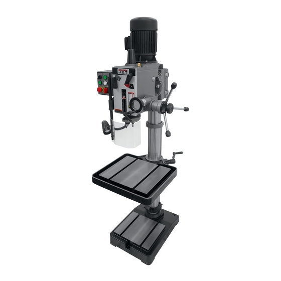
Model GHD-20PFT shown
JET
427 New Sanford Road
LaVergne, Tennessee 37086
Part No. M-354026
Ph.: 800-274-6848
Revision J1 03/2016
www.jettools.com
Copyright © 2016 JET
Advertisement
Table of Contents

Related Manuals for Jet GHD-20


Summary of Contents for Jet GHD-20
- Page 1 This .pdf document is bookmarked Operating Instructions and Parts Manual Geared Head Drilling/Tapping Presses Models GHD-20/20T/20PF/20PFT Model GHD-20PFT shown 427 New Sanford Road LaVergne, Tennessee 37086 Part No. M-354026 Ph.: 800-274-6848 Revision J1 03/2016 www.jettools.com Copyright © 2016 JET...
-
Page 2: Warranty And Service
JET sells through distributors only. The specifications listed in JET printed materials and on official JET website are given as general information and are not binding. JET reserves the right to effect at any time, without prior notice, those alterations to parts, fittings, and accessory equipment which they may deem necessary for any reason ®... -
Page 3: Table Of Contents
Parts List – GHD-20PF/20PFT Head Assembly ....................18 GHD-20/20T Head Assembly .......................... 21 Parts List – GHD-20/20T Head Assembly ....................... 22 Gear Assembly GHD-20PF, 20PFT ........................ 24 Parts List – Gear Assembly GHD-20PF, 20PFT ..................... 25 ... -
Page 4: Warning
5. Do not use this drill press for other than its intended use. If used for other purposes, JET disclaims any real or implied warranty and holds itself harmless from any injury that may result from that use. - Page 5 24. Give your work undivided attention. Looking around, carrying on a conversation and “horse-play” are careless acts that can result in serious injury. 25. Maintain a balanced stance at all times so that you do not fall or lean against the rotating spindle or other moving parts.
-
Page 6: Introduction
If there are any questions or comments, please contact either your local supplier or JET. JET can also be reached at our web site: www.jettools.com. -
Page 7: Unpacking
2. Tighten the set screw (B, Figure 1) to hold the crank in place 3. Install the handle (C, Figure 1) onto the crank 4. For the GHD-20/20T, install three handles with knobs (A, Figure 2) into the downfeed hub. For the GHD- 20PF/20PFT, screw two knobs onto the handles of the power downfeed assembly. -
Page 8: Adjusting The Head Height
Adjusting the Head Height To facilitate shipping, the Drill Press is packed with the head adjusted down on the column. The head assembly should be moved to the top of the column before drilling operation starts. The head assembly is very heavy. Use caution when adjusting the head and make sure it is supported by the table or locked in place. -
Page 9: Controls
Caution: Change speeds only when the machine is stopped. Depth Stop (GHD-20/20T) (E, Figure 8) - located on the front bottom of the head assembly. When set, the quill will only advance to a certain depth. -
Page 10: Control Panel For Ghd-20T/20Pft
Control Panel for GHD-20T/20PFT Low/Off/High Switch (A, Figure 9A) Switch between low and high speed range. In the stop position, the spindle is stopped, but the machine still has power. Drilling Tapping Selector (B, Figure 9A) For drilling, press the start switch (F, Figure 9A) to run the machine. Caution: The internal depth stop (GHD-20PFT) is used only with the tapping function. -
Page 11: Adjustments
2. Drill several test holes to make sure the depth stop is set correctly. Adjusting Depth Stop for Drilling and Tapping (GHD-20T) 1. Follow steps for GHD-20 drilling. Figure 11 2. When the tapping switch is on, the limit switches are active and will reverse rotation at the bottom of the stroke and stop rotation at the top. -
Page 12: Adjusting The Depth Stop For Drilling (Ghd-20Pf)
Adjusting the Depth Stop for Drilling (GHD-20PF) 1. Loosen the depth stop lock handle (A, Figure 12). 2. Manually advance the quill to the desired depth with one hand. 3. With the other hand, turn the depth stop scale (B, Figure 12) counter-clockwise to zero. -
Page 13: Return Spring Adjustment
Return Spring Adjustment The return spring is adjusted at the factory and should not need further adjustment. If adjustment ever becomes necessary: 1. Unplug the machine from the power source. 2. Loosen lock knob (A, Figure 14) while holding the quill spring cover. -
Page 14: Changing The Gear Box Lubricant
Changing the Gear Box Lubricant 1. Disconnect the machine from the power source. 2. Loosen nuts (A, Figure 17). 3. Tilt the head to access the drain plug. The drain plug is found in the head cavity behind the spindle. 4. -
Page 15: Troubleshooting
Troubleshooting Trouble Probable Cause Remedy Excessive vibration. Motor out of balance. Balance motor or replace. Improper quill adjustment. Adjust quill. Lubricate spindle. See the Lubrication Dry spindle. Noisy Operation. section. Check motor bearings or for a loose Noisy motor motor fan. Overfeeding. -
Page 16: Replacement Parts
Replacement Parts Replacement parts are listed on the following pages. To order parts or reach our service department, call 1- 800-274-6848 Monday through Friday, 8:00 a.m. to 5:00 p.m. CST. Having the Model Number and Serial Number of your machine available when you call will allow us to serve you quickly and accurately. -
Page 17: Ghd-20Pf/20Pft Head Assembly
GHD-20PF/20PFT Head Assembly... -
Page 18: Parts List - Ghd-20Pf/20Pft Head Assembly
Parts List – GHD-20PF/20PFT Head Assembly Index No. Part No. Description Size 40 ....GHD20PF-40 .... Screw ............... 3/16” x 3/8” ....1 42 ....61105 ......Spring Base ....................1 43 ....GHD20PF-43 .... Spring Pin ..............3 x 12 mm ..... 2 44 .... - Page 19 Index No. Part No. Description Size 123 .... GHD20-123 ....Screw ......................4 124 .... GHD20-124 ....Lamp Assembly ..................... 1 125 .... TS-2284352 ....Pan Head Screw ............M4x35L ......2 126 .... GHD20-126 ....Lamp Base..................... 1 127 ....
- Page 20 Index No. Part No. Description Size 350 .... 2450096 ....Clutch Screw....................1 351 .... 2450095 ....Clutch Nut ...................... 1 352 .... 2450068G ....Gear Box......................1 353 .... 2450081A ....Gear Shaft ..................... 1 354 ....
-
Page 21: Ghd-20/20T Head Assembly
GHD-20/20T Head Assembly... -
Page 22: Parts List - Ghd-20/20T Head Assembly
70 ....2401070 ....Lever Shaft (Right)..................1 71 ....2401071 ....Lever Shaft (Left) ................... 1 72 ....2401072 ....Name Plate (for GHD-20 only)............... 1 ....GHD20T-72 ....Name Plate (for GHD20T only not - shown) ..........1 73 .... - Page 23 123 .... GHD20-123 ....Screw ......................4 124 .... GHD20-124 ....Lamp Assembly ..................... 1 124-1 ..GHD20-124-1 .... Lamp Assembly (Independent power for GHD-20)........1 125 .... TS-2284352 ....Pan Head Screw ............M4x35L ......2 126 ....
-
Page 24: Gear Assembly Ghd-20Pf, 20Pft
Gear Assembly GHD-20PF, 20PFT... -
Page 25: Parts List - Gear Assembly Ghd-20Pf, 20Pft
Parts List – Gear Assembly GHD-20PF, 20PFT Index No. Part No. Description Size 1….…... …2401001-2 ....Main Shaft Cover ................... 1 2 ....GHD20-28 ....Oil Seal ......................1 3 ....6101-2 ....... Chuck Arbor Bolt............MT-3......1 4 .... -
Page 26: Gear Assembly Ghd-20/20T
Gear Assembly GHD-20/20T... -
Page 27: Parts List - Gear Assembly Ghd-20/20T
Parts List – Gear Assembly GHD-20/20T Index No. Part No. Description Size 1….…... …2401001-2 ....Main Shaft Cover ................... 1 2 ....6101-2 ....... Chuck Arbor Bolt............MT-3......1 4 ....GHD20-4 ....Retainer Ring ............R68 ....... 1 5 .... -
Page 28: Base, Table And Column Assembly (All Models)
Base, Table and Column Assembly (all models) -
Page 29: Parts List - Base, Table And Column Assembly (All Models)
Parts List – Base, Table and Column Assembly (all models) Index No. Part No. Description Size 201 .... 62201 ......Base....................... 1 202 .... 62202 ......Bearing Cover (lower) ..................1 203 .... 62203-1 ..... Table ......................1 212 .... -
Page 30: Control Box Assembly (All Models)
Control Box Assembly (all models) -
Page 31: Parts List - Control Box Assembly
Parts List – Control Box Assembly Index No. Part No. Description Size 401 .... GHD20PFT-401…..Control Box ....................1 ....GHD20PFT-CB ... Control Box Complete (GHD-20PFT only) ........... 1 ....GHD20T-CB ....Control Box Complete (#08050908 and higher) .......... 1 401-1 .. -
Page 32: Electrical Panel Components (Ghd-20Pft)
Electrical Panel Components (GHD-20PFT) -
Page 33: Parts List - Electrical Panel Components (Ghd-20Pft)
Parts List – Electrical Panel Components (GHD-20PFT) Index No. Part No. Description Size 1 ....ET-1311 ....Transformer ............. 230V/24V ...... 1 2 ....ET-1814 ....Fuse ................. 2A........1 3 ....ET-1215 ....Emergency Stop Switch................. 1 4 ....ET-1217 ....Start Switch....................1 5 .... -
Page 34: Electrical Schematic (Ghd-20/20Pf Only)
Electrical Schematic (GHD-20/20PF only) -
Page 35: Electrical Schematic (Ghd-20Pft)
Electrical Schematic (GHD-20PFT) -
Page 36: Electrical Schematic (Ghd-20T)
Electrical Schematic (GHD-20T)
Need help?
Do you have a question about the GHD-20 and is the answer not in the manual?
Questions and answers