
Related Manuals for Jet GHD-25


Summary of Contents for Jet GHD-25
- Page 1 DRILL PRESS GHD-25 Original: Operating Instructions JPW (Tool ) AG Tämperlistrasse 5 CH-8117 Fällanden Switzerland Phone +41 44 806 47 48 +41 44 806 47 58 www.jettools.com M-50000955T 201707...
- Page 2 Déclaration de Conformité CE Product / Produkt / Produit: Drill Press Säulenbohrmaschine Perceuse à colonne GHD-25 Brand / Marke / Marque: Manufacturer / Hersteller / Fabricant: JPW (Tool) AG, Tämperlistrasse 5, CH-8117 Fällanden Schweiz / Suisse / Switzerland We hereby declare that this product complies with the regulations Wir erklären hiermit, dass dieses Produkt der folgenden Richtlinie entspricht...
- Page 3 Make sure that the power cord does not securely on the machine, always check General safety notes impede work and cause people to trip. before switching the machine on. Milling machines can be dangerous if Keep the floor around the machine Provide workpieces with center holes not used properly.
- Page 4 Total Operation Manual page Contents 1. Main use and features of the machine 2. Main technical data 3. Brief description of the driving system and its structure 4. Electrical system 5. Lubrication system 6. Hoisting and installation 7. Use and operation of the machine 8.
- Page 5 Total Operation Manual page Dear end-user, Thank you very much for choosing our products. Please let us have the model of your machine, series number, as well as the name, address and correspondence method of your company in order to facilitate us to let you have a good service. Important notice: 1.
- Page 6 Total Operation Manual page 12. We will much appreciate if you could solve some problems of the machine. In order to facilitate us for the service, please let us know the details regarding the places and phenomenon of the troubles if you could not solve problems. 1.
- Page 7 Total Operation Manual page 2. Main technical data: 2.1 Main technical data Name of the items Unit Data Max. drilling diameter (steel) Max. tapping diameter ( s teel) Distance between spindle center line to the center line of column Max. distance between spindle end to the worktable surface of the base Max.
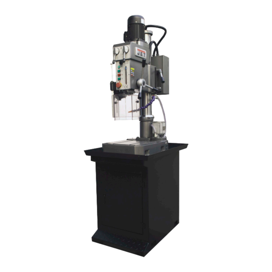
- Page 8 Total Operation Manual page 2.1 For the machine appearance and its main technical data, see diagram 1 and table 1. 3. Brief description of the driving system and its structure: The machine consists of spindle box, column, machine base, electric cabinet and machine accessories, total five component parts.
- Page 10 Total 21 Operation Manual page list of gear, worm wheel, worm and rack table(1) Number on the drawing Part drawing GHD25- GHD25- GHD25- GHD25- GHD25- GHD25- GHD25- GHD25- GHD25- 1-022 1-023 1-079 1-080 1-049 1-077 1-078 1-022 1-014 Number of teeth and starts Module...
- Page 11 Total 21 Operation Manual Page 7 Transmission Syatem Drawing (2)
- Page 12 Total 21 Operation Manual Page 8 List and distribution of rolling bearings (3)
- Page 13 Total Operation Manual page Roller bearing table Table (2) Model Name Specification Q’ty Accuracy GB276;302 Deep racing ball bearing 15 x 42 x 13 GB276;D105 Deep racing ball bearing 25 x 47 x 12 GB276,7000105 Deep racing ball bearing 25 x 47 x 8 GB276;D7000107 Deep racing ball bearing 35 x 62 x 9...
- Page 14 Total 21 Operation Manual Page 10 Push button SB3 Stop button SB2 Spindle motor M1 Reverse button SB4 Electric box B1 Emergency button Power supply switch QS1 Illuminating lamp EL1(SB5) Wiring Diagram (4)
- Page 16 Total Operation Manual page 4.3 Machine operation Put the switch (QSA1) at the position which is required (“1” main motor 1440 r/min.”2”main Motor 2880 r/min, “R” the reversion of main motor, “0” machine is stopped). Press the button SB3, it is working normally. When put the switch (QSA1) at “R”, the main motor stop working.
- Page 17 Total Operation Manual page 4.7 Electric components list: Table (3) Code of Name Specification Q’ty Remark elements Instruction switch JCH13-20 Breaker DZ108-1.6/2.5A Connector KM1,KM2 LC1E1201B5N(AC24V)50Hz LAEN20N Emergency stop button LA42(B)J-11/R Push button LA42(B)PJ-11/R SB3,SB4 Push button LA42(B)PJ-22/G Signal lamp AD17-16 AC24V Transformer JBK6-63TH 400/24 Lamp...
- Page 18 Total Operation Manual page Lubrication system: 5.1 There are two types of lubrication in this machine: a. Grease b. Lubrication by manual filled oil 5.2 Gears in the spindle box are lubricated by grease, it uses NO.3 Lithium industrial grease, for the new machine, washing and grease replacement after six months running.
- Page 19 Total 21 Operation Manual Page 15 2825 1400 4" 3" 2" 1" 0" Lubrication Diagram (6)
- Page 20 Total 21 Operation Manual Page 16 Hoisting of the machine (7)
- Page 21 Total 21 Operation Manual Page 17 1600x1000 Foundation and Installation Diagram (8)
- Page 22 Total Operation Manual page When the foundation is completely dry, the machine could be laid down on the adjustable pad. Concrete could be filled when screw bolts are placed. Fastening screw bolts after concrete is completely dry. Leveling the machine first, required tolerance should not be over 0.04/1000 both in horizontal and cross plane.
- Page 23 Total Operation Manual page 7.3 Changes for the spindle speed: Spindle speed change could be made by moving the two levers ( 10 ) and ( 11 ) located in the front of the spindle box. Relations between spindle speed revolution and levers position is indicated at the speed change label.
- Page 24 Total Operation Manual page 9.Machine use and maintenance: 9.1 Before running the machine, carefully read the Operation Manual first, fully understand the structure of the machine and its performance and needs to familiar with locations for all levers and buttons. 9.2 Lubrication of the machine is very important.
- Page 25 Total Operation Manual page 10. Machine accessories: Description Specification/standard Q’ty Remark Drill check with spanner 1-13/G86087 Adapter for drill check Shaft Adaptor 3-2/JB3477 Shaft Adaptor 3-1/JB3477 Taper wedge for flat shape quill Wedge 1/JB3482 Ø5×20 0.5A、3A Fuse Each 2...
- Page 26 Drill Press Model:GHD-25 Certificate of Inspection Max. Drilling Diameter: 25mm Series Number:...
- Page 27 Total 2 Certificate of Inspection Page 1 Precesion Inspection Record Germetrical Precision Test: Precision Item Brief Drawing Allowance(mm) Actual Test Parallelism of 0.06 at any the base tested Length surface of 300(flat or concave) Spindle bore axis runout L=100 a) Close to a ) 0.02 spindle surface b ) 0.035...
- Page 28 Total 2 Certificate of Inspection Page 2 Precesion Inspection Record Germetrical Precision Test: Precision Item Brief Drawing Allowance(mm) Actual Test Parpendicularity of the Spindle 0.07/100* sleeve to Base plate table surface (a≤90°) 0.07/100* Work Accuracy: The change of Parpendiularity of spindle axis to work table F=5000N surface under the...
- Page 29 Drill Press Model:GHD-25 Packing list Max. Drilling Diameter: 25mm Series Number:...
- Page 30 Total Packing list page Case No.: 1/1 Dimension ( L ×W × H): × × Gross weight: Net weight: Name Specification and marks Q’ty Remark Machine 1 piece Drill check with lever 1-13: GB6087 1 piece Drill check adaptor 1 piece 3-2: JB3477 1 piece Tool shank adaptor...
- Page 31 Drill Press Model:GHD-25 Ancillary page of Operation Manual Max. Drilling Diameter: 25mm Series Number:...
- Page 32 Parts Breakdown For GHD-25 Drill Press Drawing (1) , 勹 \ l : : : � 』 / 目 》 气...
- Page 33 Part List for GHD-25 DRILL PRESS Part no. Descirption Size Qty. GHD25-1-001 Knurled nob GHD25-1-002 Knurled screw bolt GHD25-1-003 Scaled screw GHD25-1-004 Scaled nut GHD25-1-005 Positioning block GHD25-1-006 Support for the indicator GHD25-1-007 Scaled indicator sheet GHD25-1-008 Spindle GHD25-1-009 Spindle cover...
- Page 34 Part List for GHD-25 DRILL PRESS Part no. Descirption Size Qty. GHD25-1-048 Spring box GHD25-1-049 Shaft GHD25-1-050 Washer GHD25-1-051 Shaft quill GHD25-1-052 Lever seat GHD25-1-053 Cover GHD25-1-054 Feed lever GHD25-1-055 GHD25-1-056 Turning lever GHD25-1-057 Lifting lever of bracket GHD25-1-058 Lifting seat...
- Page 35 Part List for GHD-25 DRILL PRESS Part no. Descirption Size Qty. GHD25-1-095 Slotted cheese head screws M4X8 GHD25-1-096 Mounting plate GHD25-1-097 Slotted cheese head screws M6X12 GHD25-1-098 Holder GHD25-1-099 Steel ball GHD25-1-100 GHD25-1-101 Lever GHD25-1-102 Screw GHD25-1-103 Sleeve GHD25-1-104 Supporting bar...
- Page 36 Parts Breakdown For GHD-25 Drill Press Drawing (2) 乒 产 1. 1 10 � : :, ' — :, , … · ; ; 勹 ` � ) 。...
- Page 37 Part List for GHD-25 DRILL PRESS Part no. Descirption Size Qty. GHD25-2-01 Base GHD25-2-02 Retainer ring GHD25-2-03 Oil plug M16X1.5 GHD25-2-04 Cover plate GHD25-2-05 Screw M6X10 GHD25-2-06 Cooling pump 0.18kW GHD25-2-07 Slotted cheese head screws M6X20 GHD25-2-08 Hose clamp GHD25-2-09 Hose Ø10X1500...
- Page 38 Standard Accessories List for GHD-25 Drill Press Part no. Descirption Size Qty. GHD25-ACC-01 Key for drill chuck GHD25-ACC-02 Drill chuck 1-13mm B16 GHD25-ACC-03 Taper wedge for shank GHD25-ACC-04 Fuse GHD25-ACC-05 Adapter MT3-1 GHD25-ACC-06 Adapter MT3-2 GHD25-ACC-07 Adapter MT3-B16...
Need help?
Do you have a question about the GHD-25 and is the answer not in the manual?
Questions and answers