Table of Contents
Advertisement
This .pdf document is bookmarked
Operating Instructions and Parts Manual
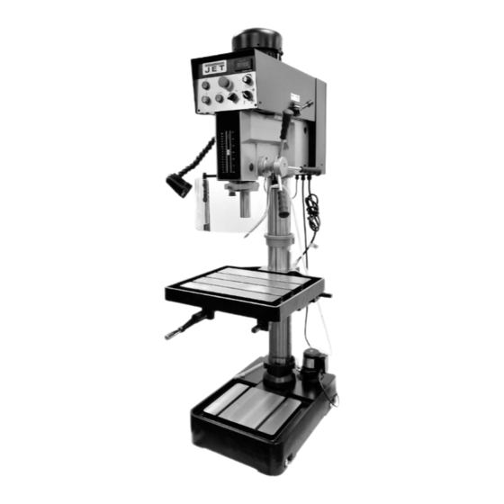
20" Electronic Variable Speed Drill Press
Models: JDP-20EVS-110, JDP-20EVST-230,-460
JDP-20EVST-230 shown
JET
427 New Sanford Road
LaVergne, Tennessee 37086
Part No. M-354220
Ph.: 800-274-6848
Edition 2 03/2017
www.jettools.com
Copyright © 2017 JET
Advertisement
Table of Contents


Need help?
Do you have a question about the JDP-20EVS-110 and is the answer not in the manual?
Questions and answers