Table of Contents
Advertisement
Quick Links
Advertisement
Table of Contents

Related Manuals for IFM Electronic GF711S


Summary of Contents for IFM Electronic GF711S
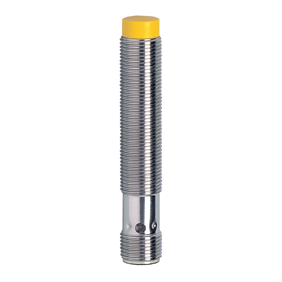
- Page 1 Original operating instructions Fail-safe inductive sensor GF711S...
-
Page 2: Table Of Contents
Contents 1 Preliminary note ���������������������������������������������������������������������������������������������������3 1�1 Symbols used ������������������������������������������������������������������������������������������������3 1�2 Warning signs used ���������������������������������������������������������������������������������������3 2 Safety instructions �����������������������������������������������������������������������������������������������4 2�1 Safety-related requirements regarding the application ����������������������������������4 3 Items supplied������������������������������������������������������������������������������������������������������5 4 Functions and features ����������������������������������������������������������������������������������������6 5 Function ���������������������������������������������������������������������������������������������������������������6 5�1 Enable zone ���������������������������������������������������������������������������������������������������6 6 Installation������������������������������������������������������������������������������������������������������������7 6�1 Protection against simple defeating ���������������������������������������������������������������8 7 Electrical connection ��������������������������������������������������������������������������������������������8... -
Page 3: Preliminary Note
1 Preliminary note The instructions are part of the unit� They are intended for authorised persons according to the EMC, Low Voltage and Machinery Directives and safety regulations� The instructions contain information about the correct handling of the product� Read the instructions before use to familiarise yourself with operating conditions, installation and operation�... -
Page 4: Safety Instructions
2 Safety instructions • Follow the operating instructions� • Improper use may result in malfunctions of the unit� This can lead to personal injury and/or damage to property during operation of the machine� For this reason note all remarks on installation and handling given in this document� Also adhere to the safety instructions for the operation of the whole installation�... -
Page 5: Items Supplied
► Replace damaged units� 3 Items supplied 1 fail-safe sensor GF711S with 2 M12 fixing nuts, 1 original instructions GF711S, ident no� 80236521� If one of the above-mentioned components is missing or damaged, please contact... -
Page 6: Functions And Features
4 Functions and features The fail-safe inductive sensor GF711S detects metal without contact� Safety function SF: the safe state (output stage switched off; logic "0") is achieved when undamping greater than or equal to the safe switch-off distance s (→ 9 Technical data)�... -
Page 7: Installation
Enable zone for selected materials*: Material Enable zone FE360 (= mild steel) 0�5���4 mm Stainless steel 0���3�1 mm AIMg3G22 0���1�8 mm CuZn37 0���2�0 mm Copper 0���1�2 mm * Typical values for damping with a reference target of 12 x 12 x 1 mm and non-flush installation to IEC 60947-5-2 at an ambient temperature of 20 °C�... -
Page 8: 6�1 Protection Against Simple Defeating
6.1 Protection against simple defeating The fail-safe sensor reacts to metal objects, e�g� the frame of a safety door� Other metal objects that are not intended to enable the sensor must not be allowed to enable the fail-safe sensor unintentionally� ►... -
Page 9: Operation
8 Operation 8.1 Switching state of the outputs 8.1.1 The safe state The safe state is when at least one of the outputs A1 or A2 (OSSDs) is switched off (zero-current state: logic "0")� If one of the outputs A1 or A2 is switched off, the subsequent safety-related logic unit must bring the complete system into the state defined as safe�... -
Page 10: 8�2 Response Times
8.2 Response times Response time on safety request ≤ 1 ms (removal from the enable zone) Response time when approaching the enable zone ≤ 1 ms (enable time) Risk time / response time for safety-related faults ≤ 20 ms Simultaneity of switching on and off of the outputs in case of a safety ≤... -
Page 11: 8�3 Led Display
8.3 LED display Operating status Outputs (OSSD) (OSSD) Signal No voltage supply Both outputs switched off Power Signal Undervoltage Power Overvoltage Both outputs switched off Signal Sensor fault One output or both Power (→ 10 Troubleshooting) outputs switched off Damping element in the Both outputs enabled enable zone Signal... -
Page 12: Technical Data
9 Technical data GF711S GIFA4004-2PS/SIL2/V4A/US Inductive sensors Product characteristics Fail-safe inductive sensor Metal thread M12 x 1 M12 connector Enable zone 0.5...4 mm; [nf] non-flush mountable Complies with the requirements: EN ISO 13849-1: 2015 category 2 PL d (can be used in applications up to cat. 3) - Page 13 Unless stated otherwise, all data refer to the 12x12x1 mm reference target plate to IEC 60947-5-2 (FE360 = mild steel) over the whole temperature range. Pack quantity [piece] ifm electronic gmbh • Friedrichstraße 1 • 45128 Essen — GB — GF711S-03 — 18.03.2016 Seite 2 von 2...
-
Page 14: Troubleshooting
10 Troubleshooting LED display → 8.3 Problem Possible cause Troubleshooting No LED display No voltage supply Apply voltage Power LED flashes and • Undervoltage Correct the voltage sensor does not switch • Overvoltage (→ 9 Technical data) Sensor does not switch, Sensor was brought into the •... -
Page 15: Terms And Abbreviations
12 Terms and abbreviations OSSD Output Signal Switch Device PDDB Proximity devices with defined behaviour under fault conditions Probability of (dangerous) Failure (PFH per Hour Performance Level PL to EN ISO 13849-1 Safety Integrity Level SIL 1-4 to IEC 61508� The higher the SIL, the lower the probability that a safety function will fail�...
Need help?
Do you have a question about the GF711S and is the answer not in the manual?
Questions and answers