Table of Contents
Advertisement
Quick Links
Advertisement
Table of Contents

Related Manuals for IFM Electronic GM701S


Summary of Contents for IFM Electronic GM701S
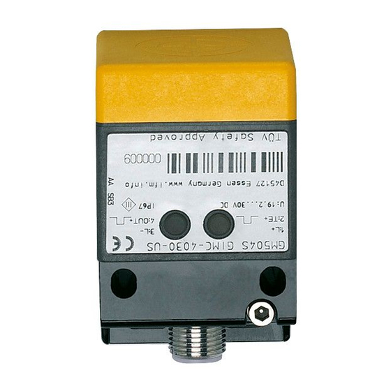
- Page 1 Original operating instructions Fail-safe inductive sensor GM701S...
- Page 2 Contents 1 Preliminary note ���������������������������������������������������������������������������������������������������3 1�1 Symbols used ������������������������������������������������������������������������������������������������3 1�2 Warning signs used ���������������������������������������������������������������������������������������3 2 Safety instructions �����������������������������������������������������������������������������������������������4 2�1 Safety-related requirements regarding the application ����������������������������������4 3 Items supplied������������������������������������������������������������������������������������������������������5 4 Functions and features ����������������������������������������������������������������������������������������5 5 Function ���������������������������������������������������������������������������������������������������������������6 5�1 Enable zone ���������������������������������������������������������������������������������������������������6 5�2 Protection against simple defeating ���������������������������������������������������������������7 6 Installation������������������������������������������������������������������������������������������������������������8 6�1 Alignment of the sensing face ������������������������������������������������������������������������8...
-
Page 3: Symbols Used
12 Maintenance, repair and disposal ��������������������������������������������������������������������19 13 Terms and abbreviations ����������������������������������������������������������������������������������20 1 Preliminary note The instructions are part of the unit� They are intended for authorised persons according to the EMC, Low Voltage and Machinery Directives and safety regulations� The instructions contain information about the correct handling of the product� Read the instructions before use to familiarise yourself with operating conditions, installation and operation�... -
Page 4: Safety Instructions
2 Safety instructions • Follow the operating instructions� • Improper use may result in malfunctions of the unit� This can lead to personal injury and/or damage to property during operation of the machine� For this reason note all remarks on installation and handling given in this document� Also adhere to the safety instructions for the operation of the whole installation�... -
Page 5: Functions And Features
4 Functions and features The fail-safe inductive sensor GM701S detects metal without contact� Safety function SF: the safe state (output stage switched off; logic "0") is achieved when undamping greater than or equal to the safe switch-off distance s (→... - Page 6 The fail-safe inductive sensor is a proximity device with defined behaviour under fault conditions (PDDB) to IEC 60947-5-3� The fail-safe sensor conforms to Performance Level e according to EN ISO 13849-1 as well as to the requirements SIL 3 to IEC 61508 and meets SILcl 3 to IEC 62061�...
- Page 7 Material Enable zone FE360 (= mild steel) 10���15 mm Stainless steel 7�5���13�2 mm AIMg3G22 2�0���5�8 mm AI 99 % 1�4���5�0 mm CuZn37 2�3���6�2 mm Copper 0�8���4�3 mm * Typical values for damping with a reference target of 45 x 45 x 1 mm and non-flush installa- tion to IEC 60947-5-2 at an ambient temperature of 20 °C�...
- Page 8 6 Installation 6.1 Alignment of the sensing face The socket is rotatable: ► Tighten the socket according to the manufacturer's indications� Observe the tightening torque for the ifm socket (e�g� EVxxxx: 0�6���1�5 Nm)� 6.2 Installation conditions • The unit is non flush mountable in steel in accordance with IEC 60947-5-2, type I2C40SP2�...
- Page 9 • The unit can be mounted flush with copper, aluminium and brass according to IEC 60947-5-2, type I1C40SP2� ► Ensure the unit cannot work loose� ► Tighten captive screws with 1 Nm� ► Limit the use of oblong holes to the initial setting� ►...
-
Page 10: Electrical Connection
7 Electrical connection Wiring diagram → 10 Technical data ► Disconnect power� Also disconnect any independently supplied relay load circuits� ► Supply voltage: connect L+ to pin 1 and L- to pin 3 of the connector� The nominal voltage is 24 V DC� This voltage may vary between 19�2 V and 30 V incl�... - Page 11 As soon as the target enters the en- able zone, the yellow LED goes out� If the target is just outside the enable zone in either direction the LED starts to flash again� Signal Signal Signal Power Power Power 1: close zone 2: enable zone 8.3 Deactivate setting aid If the sensor is undamped for more...
- Page 12 9 Operation 9.1 Switching state of the outputs 9.1.1 The safe state The safe state is when at least one of the outputs A1 or A2 (OSSDs) is switched off (zero-current state: logic "0")� If one of the outputs A1 or A2 is switched off, the subsequent safety-related logic unit must bring the complete system into the state defined as safe�...
-
Page 13: Operating Mode
9.2 Operating mode The length of the preceding undamping determines whether the yellow LED comes on with a delay (→ 9.2.1) or without delay (→ 9.2.2) when a target moves into the enable zone� In any case, the outputs switch on without delay� In case of undamping the outputs switch off and the yellow LED goes out without delay�... - Page 14 9.2.2 Switching of the LED without delay If the target was away from the sen- Undamping < 2 s: sor for less than 2 s (> 30 mm), the yellow LED comes on without delay in case of damping in the enable zone�...
- Page 15 1: Test pulse duration 2: Test pulse interval T (pulse package) 3: Test pulse interval T Test pulse interval T (repetition pulse package) min� 30 ms max� 50 ms...
- Page 16 9.4 LED display Operating status Outputs (OSSD) (OSSD) Signal No voltage supply Both outputs Power switched off Signal Undervoltage Power Signal Overvoltage Both outputs Power switched off Signal Taget outside the enable zone Both outputs Power (operating mode) or in the enable switched off zone (setting aid) Signal...
-
Page 17: Technical Data
10 Technical data GM701S GIMC-4030-US/2OSSD Inductive sensors Product characteristics Fail-safe inductive sensor Rectangular, plastics M12 connector Enable zone 10...15 mm; [nf] non-flush mountable Complies with the requirements: EN ISO 13849-1: 2015 category 4 PL e IEC 61508: SIL 3 IEC 62061: SILcl 3... - Page 18 LED yellow (signal), LED green (power) Electrical connection Connection M12 connector; Gold-plated contacts ifm electronic gmbh • Friedrichstraße 1 • 45128 Essen — We reserve the right to make technical alterations without prior notice. — GB — GM701S-03 — 02.05.2016 Seite 2 von 3...
- Page 19 60947-5-2 (FE360 = mild steel) over the whole temperature range. Pack quantity [piece] ifm electronic gmbh • Friedrichstraße 1 • 45128 Essen — We reserve the right to make technical alterations without prior notice. — GB — GM701S-03 — 02.05.2016 11 Troubleshooting LED display → 9.4...
- Page 20 13 Terms and abbreviations OSSD Output Signal Switch Device PDDB Proximity devices with defined behaviour under fault condi- tions Probability of (dangerous) (PFH Failure per Hour Performance Level PL to EN ISO 13849-1 Safety Integrity Level SIL 1-4 to IEC 61508� The higher the SIL, the lower the probability that a safety function will fail�...
Need help?
Do you have a question about the GM701S and is the answer not in the manual?
Questions and answers