Advertisement
Advertisement
Table of Contents

Summary of Contents for Bentone B10E
- Page 1 Installation- and maintenance instruction B10E 171 615 02 05-01...
- Page 2 178 072 03...
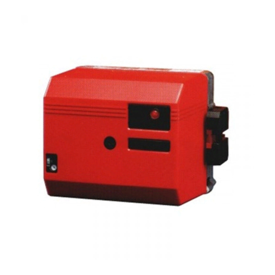
- Page 3 DESCRIPTION COMPONENTS 1. Scale, nozzle assembly 9. Ignition cables 16. Motor 10. Ignition transformer 17. Indicating lamp, preheater 2. Nozzle assembly adjustment 3. Photocell 11. Electrical connection 18. Fan wheel 4. Preheater 12. Control box 19. Air regulation 5. Nozzle 13.
-
Page 4: Technical Data
TECHNICAL DATA DIMENSIONS Flange A ø89,5 130-150 Flange B ø89,5 Burner tube Length of Flange A Flange B Flange C burner tube Measure B Measure B Measure B 130-150 Flange C ø89,5 130-150 OUTPUT RANGE AND NOZZLES RECOMMENDED Recommended Recommended Burner tube Oil capacity Nozzle... -
Page 5: General Instructions
GENERAL INSTRUCTIONS GENERAL RULES AIR ADJUSTMENT The installation of an oil burner should Install a tube in the chimney On all burners the air adjustment can be carried out in accordance with local Install a draught regulator (dilutes the be made with or without the cover regulations. - Page 6 MAINTENANCE OF OIL BURNER Warning: Before doing any service switch off power at the main switch and cut off the oil supply. SERVICE OF BURNER HEAD (alt. A) 1. Remove the cover. 2. Withdraw the photo resistor. 3. Loosen the connecting pipe. 4.
-
Page 7: Electric Equipment
ELECTRIC EQUIPMENT OIL BURNER CONTROL: LOA21... / LOA24... FUNCTION WIRING DIAGRAM Switch on operating switch and twin thermostat (1)(2) The burner motor starts, an ignition spark is formed, the prepurge goes on till the prepurge period expires and the solenoid valve opens (2). Solenoid valve opens Oil mist is formed and ignited. - Page 8 INSTRUCTIONS PUMP TYPE DANFOSS BFP41 TECHNICAL DATA Viscosity range: 1,3-12,0 mm Pressure range: 7-15 bar Oil temperature: -10 to +70°C COMPONENTS 1.Nozzle port G 1/8" 2.Pressure gauge port 3.Pressure adjustment, 4mm allen key 4.Cartridge filter 5.Vacuum gauge port G 1/8" 6.Return line G 1/4"...
- Page 9 FUNCTION DANFOSS BFP41 When the oil pump is started, oil is drawn from the suction connection (S) through the filter (H) to the suction side of the gear wheel (C). The gear wheel then pumps oil to the pressure side and the oil is put under pressure.
- Page 10 NOZZLE TABLE Pump pressure bar kg/h kW Mcal/h kg/h kW Mcal/h kg/h kW Mcal/h kg/h kW Mcal/h kg/h kW Mcal/h kg/h kW Mcal/h kg/h kW Mcal/h kg/h kW Mcal/h 0,40 1,33 1,41 1,49 1,56 1,63 1,70 1,76 1,82 0,50 1,66 1,76 1,86 1,95...
-
Page 11: Fault Location
FAULT LOCATION BURNER FAILS TO START Situation Possible causes Remedies Motor runs Flame instabillity Check nozzle to burner head dimension and Incorrect head settings Burner pre-purges electrode position Check oil pressure Low oil pressure Adjust air damper Flame occurs Excess air Burner locks out Photocell not seeing light Check that photocell is clean and unobstructed... -
Page 12: Declaration Of Conformity
DECLARATION OF CONFORMITY (supplier´s name) BENTONE ............(address) P.O. Box 309, S-341 26 Ljungby, Sverige ..............declare under our sole responsibility that the product (name, type or model, batch or serial number, possibly sources and number of items) ST 97, ST 108, ST 120, ST 133, ST 146, B 9, B 10, B 11, B 20, B 30, B 40, B 45, B 50, B 60, B 70, B 80, ...................................... - Page 13 To fulfil the demands according to the Efficiency directive 92/42/EEC, Article 2, we herewith state the following parameters. Burner Capacity Test report No. Pressure in combustion Product ID-No. as per type kg/h (kW) TÜV chamber mbar EC-Type Examination Certificate ST 97 1,2-2,6 3728 -0,2 to+1,4...
- Page 14 To fulfil the demands according to the Efficiency directive 92/42/EEC, Article 2, we herewith state the following parameters. Burner Capacity Test report No. Pressure in combustion Product ID-No. as per type kg/h (kW) TÜV chamber mbar EC-Type Examination Certificate B 50-2F 12,0-59,0 3390 -0,2 to +9,4...


Need help?
Do you have a question about the B10E and is the answer not in the manual?
Questions and answers