Bentone BG450M Installation And Maintenance Instructions Manual
Hide thumbs
Also See for BG450M:
- Installation and maintenance instruction (17 pages) ,
- Installation and maintenance instruction (48 pages) ,
- Installation and maintenance manual (64 pages)
Table of Contents
Advertisement
Quick Links
Advertisement
Table of Contents

Subscribe to Our Youtube Channel
Related Manuals for Bentone BG450M


Summary of Contents for Bentone BG450M
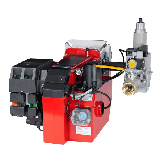
- Page 1 178 016 76 Installation- and maintenance instruction BG450M...
- Page 2 DESCRIPTION Warning – Read the manual before assembling or commissioning. – The contents of this manual are to be observed by all who work for any reason on the unit and its appertaining system parts. – This manual is intended especially for authorised personnel. –...
- Page 3 DESCRIPTION Components 11. Connection gas fittings 1. Flame cone 18. Switch l-ll (For modulating burner: 2. Inner assembly 12. Air intake 3. Fixing flange Change-over switch manually- 13. Air damper automatically) 4. Electric panel 14. Air pressure switch 19. Indicating lamp Stage 1 5.
-
Page 4: Technical Data
TECHNICAL DATA Type designation BG 450 Dimensions Length of burner Flange tube Measure A Standard Long design The above dimensions are max. measurements. Depending on the components used, the measurements may vary. Out range Type Capacity Gas volume at a min. Gas volume at a max Max. - Page 5 TECHNICAL DATA DIMENSIONS OF FLANGE 172 215 19 08-01...
-
Page 6: Skeleton Diagrams
5 a. Gas pressure switch, mini 7. Valve proving system 5 b. Gas pressure switch, maxi 8. Air damper motor 9. Air pressure switch 10. Gas burner control Pos. When Bio gas is used, Bentone shall always be contacted. 172 415 09 08-01... - Page 7 MOUNTING OF THE BURNER Fit the burner to the boiler by means When the burner head and the gas Ensure that the O-ring between the of 4 bolts M12. For flange and bolt flange have been fitted to the boiler it gas assembly and the gas flange will dimensions see technical data.
-
Page 8: Electric Equipment
ELECTRIC EQUIPMENT Gas burner control: LMG22/LME22 Wiring diagram 1(5) 172 425 61 08-01... - Page 9 ELECTRIC EQUIPMENT Gas burner control: LGB22/LMG22/LME22 List of components Main switch Air pressure switch Gas burner control Gas pressure switch Power control S11 Change-over switch, Aut.-Man. Ionization electrode S12 Change-over switch, Increase-Decrease Operating fuse S15 Control thermostat, 3-pole (only for 2-stage sliding) Operating lamp Ignition transformer Alarm signal 230 V...
- Page 10 ELECTRIC EQUIPMENT Control diagnosis under fault conditions and lockout indication Gas burner control: LMG ... Diagnosis of cause of fault After lockout, the red fault LED is steady on. For reading the cause of fault, refer to the blink code given in the following table: Press lockout reset button Red LED on LED on (waiting time≥10 s)
- Page 11 ELECTRIC EQUIPMENT Control diagnosis under fault conditions and lockout indication Gas burner control: LME..Colour codes Colour code table for multi-coloured signal lamps (Light diodes) Status Colour codes Colours ○………………… Waiting time «tw», other waiting times •○ •○ •○ •○ •○ • Ignition phase, ignition checked Flashing yellow □…………………...
- Page 12 ELECTRIC EQUIPMENT Control diagnosis under fault conditions and lockout indication Gas burner control: LME... Alarm control table Red flashing code Possible causes on signal lamp (LED) No flame at End of «TSA» Flashing 2 x •• – Defective or obscured flame monitor –...
- Page 13 MEASURES AND CHECKS BEFORE START-UP, 2-STAGE- OR MODULATING BURNERS General rules Leakage control Care should be taken by the installer Note on 2-stage and modulating burn- MultiBloc to ensure that no electrical cables or ers that during the pre-purging period fuel/gas pipes are trapped or damaged the damper opens to the set value for air on stage 2 and just before the end...
- Page 14 MEASURES AND CHECKS BEFORE START-UP Inner assembly Town gas Inner assembly Natural gas, LPG Propan Natural gas Inner assembly Biogas ((UV-detector) 172 205 18 08-01...
- Page 15 DETERMINATION OF GAS VOLUME FOR THE INSTALLATION Specifications on natural gas, town Net calorific value gas and bio gas vary. For more exact Gas quality kWh/Nm kJ/Nm kcal/Nm information please contact the gas Natural gas 10,3 37 144 8 865 distributor.
- Page 16 DUNGS COMBI BLOC WITH RATIO ADJUSTMENT MB-VEF BO1, 412 - 425 View 17 2 16 11 18 - 425 B01 1. Electrical connection gas pressure switch mini 1. Electrical connection gas pressure switch mini 2. Electrical connection gas valve 2. Electrical connection gas valve 3.
-
Page 17: Adjustment Possibilities
TECHNICAL DATA WITH RATIO ADJUSTMENT - Max inlet pressure 360 mbar - Gas family 1 +2 +3 - Valves V class A group 2 in accordance with EN - Outlet pressure 0,5 - 100 mbar - Zero point adjustment N ±2 mbar - Governor class A group 2 in accordance with EN88 - Pressure switch DIN3398 TI - Ratio V P... - Page 18 ADJUSTMENT OF GAS FLOW Damper motor, air volume Adjust the orange cam for min. load (about 5-10 on scale) Adjust the red cam for max. load (90° ) The blue cam is factory set for closed position during standstill The black cam has no function at modulating operation Gas valve (black) Max.
-
Page 19: General Instructions
GENERAL INSTRUCTIONS Adjustment of burner A general rule is that the lower capacity Service the smaller the opening between The burner is from the factory pre-set Service should only be carried out by qualified personnel. Replacement brake plate and combustion device. to an average value that must then be adjusted to the boiler in question. -
Page 20: General Instruction
GENERAL INSTRUCTION Flame monitoring and measure- Adjustemnt of max. gas pressure Adjustment of air pressure switch ment of ionisation current switch The air presure switch should stop the The burner is monitored according The burner is equipped with a max. burner if the air volume is reduced. -
Page 21: Handing Over Of The Installation
HANDING OVER OF THE INSTALLATION – Make repeated start attempts to Fault location, functional troubles ensure that the adjustments Trouble free operation is dependent function. on three factors: electricity, gas and air supply. Should there be any changes – Close the ball valve during in the ratio between these three factors operation to check that the gas there is a risk of break downs. -
Page 22: Gas Burner
FAULT LOCATION GUIDE Gas burner To facilitate fault location we have drawn up a scheme The basis for trouble free operation can only be ensured showing the most frequent faults in a gas burner instal- by the correct combined effect of the three factors: electricity, gas flow and combustion air. - Page 23 REMEDY CAUSE The cable shoes have bad contact Improve the contact The ignition cables are damaged Replace The ignition transformer is damaged, no voltage Replace the transformer on the secondary side The ignition cable and the ionisation cable have Change been transposed.
- Page 24 REMEDY CAUSE Voltage lower than 185 V Contact the electricity authorities. Adjust the ignition electrodes, repole the ignition The ignition electrodes are disturbing the ionisation current transformer if necessary. Bad earthing Arrange for proper earthing. Phase and neutral transposed See wiring diagram and change. The burner locks out during pre-purge Air pressure switch defective or incorrectly adjusted The starting load is not correctly adjusted...
- Page 25 REMEDY CAUSE The ambient temperature of the gas relay is too high Heat insulate, max. 60° C. The ignition spark is too weak Check the transformer Bad combustion Bad draught conditions Check the chimney The flue gas temperature is too high The boiler is overloaded.
-
Page 26: Declaration Of Conformity
DECLARATION OF CONFORMITY (supplier´s name) ENERTECH AB (Address) Box 309, S-341 26 Ljungby, Sverige declare under our sole responsibility that the product (name, type or model, batch or serial number, possibly sources and number of items) BG100, BG150, BG200, STG120, STG146, BG300, BG300LN, BG400, BG400LN, BG450, BG450LN, BG500, BG550, BG550LN, BG600, BG600LN, BG650, BG700, BG 700LN, BG800, BG800LN and BG950 all fan gas burners to which this declaration relates is in conformity with the following standard(s) or the normative socument(s)
Need help?
Do you have a question about the BG450M and is the answer not in the manual?
Questions and answers