Table of Contents
Advertisement
Quick Links
Advertisement
Table of Contents

Subscribe to Our Youtube Channel
Related Manuals for AXIOMTEK MMT175


Summary of Contents for AXIOMTEK MMT175
- Page 1 MMT175 17” TFT Medical Grade LCD Monitor User’s Manual...
- Page 2 AXIOMTEK does not warrant or assume any legal liability or responsibility for the accuracy, completeness or usefulness of any information in this document. AXIOMTEK does not make any commitment to update the information in this manual.
-
Page 3: Safety Approvals
Safety Approvals CE Marking UL60601-1 EN60601-1 FCC Class B FCC Compliance This equipment has been tested in compliance with the limits for a Class B digital device, pursuant to Part 15 of the FCC Rules. These limits are meant to provide reasonable protection against harmful interference in a residential installation. -
Page 4: Safety Precautions
Safety Precautions Before getting started, please read the following important safety precautions. The MMT175 does not come equipped with an operating system. An operating system must be loaded first before installing any software into the computer. Be sure to ground yourself to prevent static charge when installing the internal components. - Page 5 When handling boards and components, wear a wrist- grounding strap, available from most electronic component stores. Trademarks Acknowledgments AXIOMTEK is a trademark of AXIOMTEK Co., Ltd. PC/AT, VGA are trademarks of International Business Machines Corporation. ® Intel is registered trademarks of Intel Corporation.
-
Page 6: Table Of Contents
Table of Contents Disclaimers ................ii Safety Approvals..............iii Safety Precautions..............iv CHAPTER 1 INTRODUCTION ........1 General Description ..........1 Package List ............3 Specifications............4 Dimensions ............5 I/O Outlets............6 CHAPTER 2 SYSTEM SETUP ........8 System Configuration ......... 8 OSD Setting............ - Page 7 MEMO...
-
Page 9: Chapter 1 Introduction
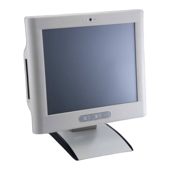
I/O Outlets Package List General Description The MMT175 is a Medical Grade LCD Monitor. It adopts a 17” 300nits SXGA LCD display, and numerous signal interfaces including DVI, VGA, S-Video, Video, Audio-in and 3 USB (1 slave, 2 hosts). There is an OSD function making you ease adjustment on screen image. - Page 10 Support VGA (640 x 480), SVGA (800 x 600), XGA (1024 x 768), SXGA (1280 x 1024). Multi-signal inputs Support VGA, S-video, video, DVI, Audio-in, 3 USB ports (2 × type A, 1 × type B), so the MMT175 can receives TV and PC signals. Introduction...
-
Page 11: Package List
MMT175 User’s Manual Package List When you receive the MMT175, the bundled package should contain the following items: MMT175 x 1 Driver CD x1 Medical Power Adapter x1 USB cable x 1 Audio cable x 2 VGA cable x 1... -
Page 12: Specifications
MMT175 User’s Manual Specifications Display Tyep: 17” TFT LCD Max. Resolution: 1280 x1024 Brightness: 300nits Max. Colors: 16.7M View Angle: H:160° / V:160° Front Bezel: Plastic ABC Control: OSD (On Screen Display) control pad on front side IO outlets 1 x Audio, 1 x VGA, 1 x DVI, 1 x USB (Slave, for DSC, T/S) -
Page 13: Dimensions
MMT175 User’s Manual Dimensions This diagram shows you dimensions and outlines of the MMT175. Introduction... -
Page 14: I/O Outlets
MMT175 User’s Manual I/O Outlets Please refer to the following illustration for I/O locations of the MMT175. ○ ○ ○ ○ ○ ○ ○ ○ ○ ○ ○ ○ ○ ○ ○ ○ Function Camera Auto-Adjusted / Return Menu SEL+ / SEL-... - Page 15 MMT175 User’s Manual Monitor Switch Audio(Line-out) S-video Video Power switch Audio (Mic-in) USB2.0 × 2 USB (type B) DC-in power connector Introduction...
-
Page 16: Chapter 2 System Setup
OSD Setting Wall Mount / VESA / Desktop Stand methods System Configuration The MMT175 provides display control on screen display. The descriptions of the functions are listed below. 1. Monitor switch: Press this button to turn on/off the monitor. 2. Power LED: When the light is green, the power is on, flash when the power is turn off. - Page 17 MMT175 User’s Manual 5. Menu: Press this button to turn on/off the OSD (On Screen Display). 6. Auto-Adjusted / Return: This button is auto image adjustment and return. System Setup...
-
Page 18: Osd Setting
MMT175 User’s Manual OSD Setting The MMT175 provides OSD (On Screen Display) to adjust brightness, contrast, clock…et al. Please follow the steps are listed as below. 1. Please press the “Menu” button on the OSD keypad. You could see General menu. If you want to adjust sub-item, you could press the “Menu”... - Page 19 “Menu” button on the OSD keypad. 4. Please press the “SEL-“button on the OSD keypad. You will entry Languages menu. MMT175 support 8 languages (English, French, German, Spanish, Italian, Japanese, Russian and Chinese). 5. Please press the “SEL-“button on the OSD keypad. You will entry...
- Page 20 MMT175 User’s Manual Tools menu. If you want to adjust sub-item, you could press the “Menu” button on the OSD keypad. 6. Please press the “SEL-“button on the OSD keypad. You will entry Exit menu. If you want to leave the OSD, you would press “menu”.
-
Page 21: Mount Methods
MMT175 User’s Manual Mount Methods There are several mounting ways for the MMT175, Wall, VESA and Desktop mountings. 2.3.1 Wall Mount The MMT175 provides wall mount kit. Please follow the steps as below. Prepare all parts for installing the wall mount kit. -
Page 22: Vesa Mount
MMT175 User’s Manual 2.3.2 VESA mount The MMT175 provides two types of VESA mount, 75mm x 75mm and 100mm x 100mm. System Setup... -
Page 23: Desktop Stand
MMT175 User’s Manual 2.3.3 Desktop Stand The MMT175 provides desktop stand (optional) that customer can install as below. Step 1 Prepare the parts of desktop stand. Screw A Screw B Screw C Hinge Cover System Setup... - Page 24 MMT175 User’s Manual Step 2 Assemble the desktop stand. Fix the screws as marked on the bottom side of chassis. (Use Screw A) Step 3 Fix the screws as marked on the back side of chassis (Use Screw B). System Setup...
- Page 25 MMT175 User’s Manual Step 4 Assembly the hinge cover and fix the screws as marked on the back side of chassis (Use Screw C). System Setup...
- Page 26 MMT175 User’s Manual Step 5 Finish. System Setup...
- Page 27 MMT175 User’s Manual MEMO System Setup...
-
Page 28: Chapter 3 Drivers Installation
MMT175 User’s Manual CHAPTER 3 DRIVERS INSTALLATION System MMT175 supports Windows XP. To facilitate the installation of system driver, please carefully read the instructions in this chapter before start installing. The installation method of the touch and Bluetooth (optional) are listed below. -
Page 29: Driver Installation- Windows Xp
MMT175 User’s Manual 3.2.2 Driver Installation- Windows XP The MMT175 provides a touch screen driver that users can install it under the operating system Windows XP. To facilitate installation of the touch screen driver, you should read the instructions in this chapter carefully before you attempt installation. - Page 30 MMT175 User’s Manual Click Start menu and select “PenMount Utilities”; and then, a “PenMount Control Panel” pops out. Select the “Standard Calibrate” tab. Calibration: Drivers Installation...
- Page 31 MMT175 User’s Manual To adjust the display with touch panel, click “Calibration” and follow the calibrate point to do calibration; there are five points on screen for calibration. Press OK. Drivers Installation...
-
Page 32: Bluetooth (Optional)
MMT175 User’s Manual Bluetooth (optional) The MMT175 provides users to extra add Bluetooth function. Users can install the Bluetooth driver under the operating system Windows XP. To facilitate installation of the touch screen driver, you should read the instructions in this chapter carefully before you attempt installation.
Need help?
Do you have a question about the MMT175 and is the answer not in the manual?
Questions and answers