
Related Manuals for Vivotek NR8401


Summary of Contents for Vivotek NR8401
- Page 1 VIVOTEK - Built with Reliability NR8401 Network Video Recorder User’s Manual 16-channel • Rack-mount Enclosure • Full Integration with VIVOTEK Cameras Rev. 1.6.1.11 Rev. 1.0 Rev. 1.1 User's Manual - 1...
-
Page 2: Table Of Contents
VIVOTEK - Built with Reliability Table of Contents Revision History ..............................4 Chapter One Hardware Installation and Initial Configuration ..................5 Introducing NR8401 Network Video Recorder ....................... 5 Special Features ............................. 5 Safety ................................6 Physical Description ............................. 7 Hardware Installation .............................. 9 Network Deployment ............................ - Page 3 VIVOTEK - Built with Reliability 3-2-2. Network - DDNS ..........................69 3-2-3. Network - Service ..........................71 3-2-4. Network - Utility ........................... 72 3-3. Camera ................................. 73 3-3-1. Camera - General ..........................73 3-3-2. Camera - Video ........................... 79 3-3-3. Camera - Schedule ..........................80 3-4.
-
Page 4: Revision History
VIVOTEK - Built with Reliability Revision History Rev. 1.0: Initial release. Rev. 1.1: * Added description for the NVR DI/DO-related functions, including DI/DO connections, Toggle DO, NVR DI as Alarm triggers, etc. * Added description for the Alarm History. * Added description for the Default routing interface. -
Page 5: Chapter One Hardware Installation And Initial Configuration
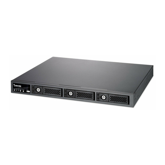
NVR configurations, which is very useful for a rack- mount chassis system. Up to 4 HDDs can be added to the NR8401 for a total storage capacity of up to 16TB (4TB*4). Three removable HDD trays are available in the front of the unit, with hot-swap functionality for easy replacement, and support the RAID 0/1/5 application for video data protection and mirroring. -
Page 6: Safety
VIVOTEK - Built with Reliability Safety Connect the system to an earthed main power outlet. Never open the housing of the power supply unit. Install and operate the system only in a dry, weather-proof location. Observe the following safety factors: Is there visible damage to the system or power cord •... -
Page 7: Physical Description
VIVOTEK - Built with Reliability Physical Description Front View Disk 1 Disk 2 Disk 3 1 Power button and LED Disk 4 can be installed inside the 2 Status LED chassis. See page 17 for information. 2 3 4 3 HDD activity LED... - Page 8 VIVOTEK - Built with Reliability The digital output connection is diagrammed as follows: Switch Switch Max. BJT transistor BJT transistor Source Source Relay Relay Device Device The maximum load on DO pins is 50mA. IMPORTANT: It is important to leave a clearance of 10cm to the rear side of the chassis.
-
Page 9: Hardware Installation
VIVOTEK - Built with Reliability IMPORTANT: For a RAID volume configuration, it is recommended you use hard drives of the same model featuring the same capacity and rotation speed. It is also preferred that these drives are running the same version of firmware. - Page 10 VIVOTEK - Built with Reliability IMPORTANT: Avoid touching the hard drive's circuit board or connector pins. Doing so can damage the hard drive by electro-static discharge. 3. Insert the hard drive into drive bay. 4. 4-1. Push the hard drive into bay until you feel the contact resistance.
-
Page 11: Interface Connections
VIVOTEK - Built with Reliability Interface Connections 1 & 2. Connect CAT5e or better-quality Ethernet cables to cameras via a local, switched net- work, or clients through the Internet. Refer to next page for more information. 3. Connect USB devices such as USB optical drive or UPS. -
Page 12: Network Deployment
VIVOTEK - Built with Reliability Network Deployment 1. Connect network cameras to the NVR’s LAN ports. 2. Internet access to the NVR is made through the TCP port 80 and RTSP streaming via port 554. Clients Router Internet Router Switch... -
Page 13: Initial Configuration
2. From a management computer, install the IW2 utility software included in the product CD. Follow the onscreen instructions to complete the installation. 3. Start the IW2 utility. The IW2 utility will discover the NR8401 located in the same subnet. 4. Double-click on the NR8401 entry to start a web session with the NVR system. - Page 14 VIVOTEK - Built with Reliability 6. The system will default to the LiveClient page. Click on the Settings button on the upper right corner of the screen. 7. On the Settings page, click on Storage > Volume to access your storage volume configuration.
- Page 15 VIVOTEK - Built with Reliability 9. Depending on the number of hard drives you installed, a list of RAID volume configurations will be listed. Select a configuration's check circle and the disk members of a volume, and then click OK to continue. The initialization of a RAID volume will take several minutes.
- Page 16 VIVOTEK - Built with Reliability 12. Click on Camera > General on the menu tree to open the camera settings page. Click on the Search button to locate cameras installed in the subnet. 13. Cameras on the network will be listed. Click on the + button on the far left to enlist them into your configuration.
- Page 17 VIVOTEK - Built with Reliability NOTE: If you need to install 4 hard drives, 1. Power down the system and disconnect the power cord. 2. Open the chassis top cover by removing 4 screws from the sides, and then the hand screw at the rear side of the chassis.
-
Page 18: Rack-Mounting
VIVOTEK - Built with Reliability Rack-mounting IMPORTANT: If you have either a round-holed or square-holed rack, install cage nuts or clip nuts to the desired positions on the rack posts. The instructions below are based on the installation to a 4-post equipment rack. - Page 19 VIVOTEK - Built with Reliability 3. Secure the inner rails to the sides of the chassis using M4 screws. 4. Secure the L-shape brackets to the front- and rear-ends of outer rails using the black round head screws and washers. Do not completely tighten the screws yet. Adjust the length of slide rails by extending and matching the rails between rack posts.
- Page 20 VIVOTEK - Built with Reliability Adjusting the length of rails. 5. Secure the slide rails to rack posts using 8 M5 screws. 20 - User's Manual...
- Page 21 VIVOTEK - Built with Reliability 6. Hold the chassis using hands on the sides of the chassis. Align the inner rails on the chassis with the open portion of the slide rail assemblies. Push the system into the assemblies until the system stops.
- Page 22 VIVOTEK - Built with Reliability 7. The inner rails and the rail assemblies should be locked on the way into the rack cabinet. Press the release tabs on the side to slide the chassis into rack. Release tab 8. Secure the chassis to rack posts using a long M5 screw.
-
Page 23: Attaching Foot Pads
VIVOTEK - Built with Reliability Attaching Foot Pads If you intend to place your chassis on a shelf or desktop, attach the foot pads to the bottom of the chassis where you can find corner marks for reference. LED Indicators... -
Page 24: Power Up And Power Down
1. No storage system is completely fail-safe. Damage to data might occur due to file system corruption, operating system malfunction, virus infection, HDD component failures, and so on. Therefore, it is highly recommended to regularly back up your data, and VIVOTEK disclaims responsibilities of data loss or recovery. -
Page 25: Chapter Two Login And Getting Started
VIVOTEK - Built with Reliability Chapter Two Login and Getting Started 2-1. Login This is the login page on the browser. The minimum for resolution is 1280x960. If you enable the IE7 compatible mode when using the IE8 browser, please disable the compatibility function. - Page 26 VIVOTEK - Built with Reliability You may login to a different software utility by unfolding the side panel on the Login button. You can also select a different language using the Multilingual selector menu on the lower left corner of the Login screen.
- Page 27 VIVOTEK - Built with Reliability Login options: You may also mouse over the Login button to display the login options. You can then enter the Liveview, Playback, or Settings window. The NVR system features a very simple UI structure which consists of a Liveview window, a Playback utility, and a system Settings window.
- Page 28 VIVOTEK - Built with Reliability IMPORTANT: 1. Before operating the NVR, make sure you have properly installed hard drives and configured the storage volumes. Otherwise, you will not be able to operate or try some of the system's functionality. 2. Since the NVR system comes with 32-bit plug-ins for screen control, if your PC runs a default 64-bit IE browser and you manually enter the NVR's address on the browser, your browser session may malfunction.
-
Page 29: Graphical Layout And Screen Elements - Liveview
VIVOTEK - Built with Reliability 2-2. Graphical Layout and Screen Elements - Liveview Layout Camera list Layout contents Logo & Menu Alarm panel panel Viewcell panel Once you log in, the system defaults to the Liveview page, which provides access to other configuration utilities, live view screen, and other functional panels. -
Page 30: Camera List Panel
VIVOTEK - Built with Reliability 2-2-1. Camera List Panel The camera list displays the 16 recruited cameras by the sequential numbering order you configured in the System Settings utility. Sorting criteria Camera thumbnails Page switcher Depending on the size and screen resolution of your monitor, the snapshots of 5 or 9 cameras are displayed in this panel, and you should use the Page switcher buttons to see the rest of the cameras. - Page 31 VIVOTEK - Built with Reliability * Snapshot: the camera's image snapshot is replenished every 5 minutes. If a camera is disconnected, the last image taken will be used to represent a camera. * Camera index & Camera name: Placing the mouse cursor on top of a camera text displays the camera index number and the camera name.
-
Page 32: Layout
VIVOTEK - Built with Reliability 2-2-2. Layout By default, 5 typical layouts are provided for the user. They include: 1x1, 1+3, 2x2, 1+5, and 4x4. System default is the 4x4 layout. Cameras that do not fit into the first page of a layout, say, a 2x2 layout, will be displayed on the succeeding layout pages. -
Page 33: Layout Contents
VIVOTEK - Built with Reliability 2-2-3. Layout contents A few functional buttons are available on the Layout contents page. Clears all view cells on the current layout Full view: extends the view cells on the current layout to the full of the screen. -
Page 34: View Cell Panel
VIVOTEK - Built with Reliability 2-2-5. View Cell panel A single view cell is shown below. Each view cell contains a video stream display area, an information bar, and functional buttons at the bottom. A view cell is displayed in Normal, Focused, or Maximized mode. - Page 35 VIVOTEK - Built with Reliability A view cell attempting to connect to a network camera will look like this. If the connection attempt takes a long time, it may result from network problems or incorrect configuration with video streaming. For example, you may have configured the camera to be streaming channel #2 using the MJPEG mode, which is not supported by the system.
- Page 36 VIVOTEK - Built with Reliability Information Bar Status icon Camera index Video time Status icon Description Connected with live streaming; a single click on this icon can trigger a manual recording. Connected and recording video to system storage. Disconnected or trying to establish a connection.
- Page 37 VIVOTEK - Built with Reliability The time display formats are slightly different for different languages: English M/d/yyyy H:mm:ss AM/PM 5/3/2011 1:07:05 AM Deutsch yyyy/MM/dd HH:mm:ss 03.05.2011 01:07:05 Español yyyy/MM/dd HH:mm:ss 03/05/2011 1:07:05 Français yyyy/MM/dd HH:mm:ss 03/05/2011 01:07:05 Italiano yyyy/MM/dd HH:mm:ss...
- Page 38 VIVOTEK - Built with Reliability Buttons Description Volume controller Fisheye display modes - if the view cell contains video from a fisheye camera, the fisheye display mode selector will be available: 1O: the orginal circular view. 1P: the panoramic view.
- Page 39 VIVOTEK - Built with Reliability Below are two bookmarks (yellow tags) shown along with a recorded video in the Playback utility screen. Bookmarks help find and retrieve important moments in a recoded video. NOTE: Bookmarks will be erased if the user/system erases the video clips they were appended to. For example, system will recycle storage space by deleting old videos along with their bookmarks.
-
Page 40: Global View
VIVOTEK - Built with Reliability 4. Clear: This button removes camera from the current view cell. The view cell will then be available for other cameras 5. Mute and Unmute: These buttons stops or resumes audio from a live stream. - Page 41 VIVOTEK - Built with Reliability 9. Volume controller: The volume control takes effect when audio input from the network camera is available. Audio is heard only from a focused window, one that you selected by a mouse click form the Liveview panel.
- Page 42 VIVOTEK - Built with Reliability 1R (Regional view) 1R View (Single Regional View) Zoom Out Zoom In Zoom in/out & all-directional navigation control The 1R mode (or rectilinear) provides access to one image section within the hemisphere. You can zoom in or out (using the mouse wheel or PTZ panel) or travel through to other areas within the hemisphere using simple mouse clicks and drags.
-
Page 43: Ptz Panel
VIVOTEK - Built with Reliability 2-2-6. PTZ panel The PTZ panel takes effect for cameras that come with mechanical PTZ functions. It does not support digital PTZ functions. To utilize its functions, select a view cell populated by a PTZ camera, such as a speed dome. - Page 44 VIVOTEK - Built with Reliability PTZ presets: If your PTZ cameras have preset locations, click on the button to unfold the preset menu. Click on any of the preset locations to move to the area of your interest. Refer to your camera's User Manual for how to configure preset locations.
-
Page 45: Alarm Panel
VIVOTEK - Built with Reliability Auto pan/patrol controller: These buttons provides pan and patrol functions provides that preset locations have been configured on the camera. For a speed dome camera, the pan command tells the camera to continuously pan 360 degrees until stopped by a user command. - Page 46 VIVOTEK - Built with Reliability The alarm panel is displayed either in the list mode or the icon mode If an event is configured with a recording action, or the alarm is triggered when the associated camera was recording to the NVR, there will be a play button to the left of the alarm message.
- Page 47 VIVOTEK - Built with Reliability You can click on the icon mode button to have a glimpse of alarms indicated by their snapshots taken by the time of the occurrences. If the alarm is triggered by NVR DI pins, no snapshots will be available.
- Page 48 VIVOTEK - Built with Reliability Incoming Alarms New alarms will be indicated by the messages in bold letters, the alarm bell icons, and the increasing number of unread messages on the title bar. A text-based history of past Alarms is accessed through the Alarm - History page in the Settings window.
-
Page 49: Graphical Layout And Screen Elements - Playback
VIVOTEK - Built with Reliability 2-3. Graphical Layout and Screen Elements - Playback Layout contents Logo & Menu Camera list Calendar Alarm panel Playback panel The screen elements of the Playback window are described as follows: Item Name Description Camera List Provides a glimpse of all cameras that have recorded data. -
Page 50: Camera List Panel
VIVOTEK - Built with Reliability 2-3-1. Camera List Panel The camera list displays the 16 recruited cameras by the sequential numbering order you configured in the System Settings window. The elements in the Camera list on a Playback window are identical to those on a Liveview window. Please refer to page 30 for details on the Camera list panel. -
Page 51: Playback Layout
VIVOTEK - Built with Reliability 2-3-2. Playback Layout 3 types of layouts are provided for the Playback window. They include: 1x1, 2x2, and 1+3. In the playback window, users can simultaneously playback up to 4 recorded videos. Clears all view cells on the current layout Starts or stops the Synchronous playback. -
Page 52: Playback View Cells
VIVOTEK - Built with Reliability 2-3-4. Playback View Cells The view cells in Liveview and Playback windows are similar. Their differences are listed as follows: 1. 3 simple layout types are supported as previously discussed. 2. The information bar displays camera index and video time information only. -
Page 53: Playback Control Panel
VIVOTEK - Built with Reliability Playback control panel Timeline slider Span of existing recording Control buttons Timeline zoomer Playback info The time slide bar enables quick skimming through the recording. Its functional buttons are described as follows: Buttons Description Pause Play. - Page 54 VIVOTEK - Built with Reliability Timeline zoomer. Use the zoomer to zoom in for more precise skimming. Timeline slider thumb. Click and drag this thumb button to move along and reach a specific point in time. A click on the time line will also work.
-
Page 55: Alarm Panel
VIVOTEK - Built with Reliability 2-3-5. Alarm Panel The alarm panel displays the alarms or bookmarks recorded by the day of recording. Two additional buttons are available: Page selector and Alarm filter. Page selector Alarm filter See page 99 for how to configure alarms. -
Page 56: Calendar Panel
VIVOTEK - Built with Reliability 2-3-6. Calendar Panel Double-click on any of the existing cameras to display the Calendar panel. Days with recorded videos will be highlighted in blue regardless of the length of existing recordings that occurred in that day. You may then click on a day to begin viewing the past recordings. -
Page 57: Chapter Three System Settings
VIVOTEK - Built with Reliability Chapter Three System Settings The Settings window is accessed by clicking on the Settings button on the Logo panel. You will enter the Overview of the Settings window. All the configuration menus are placed under 7 major categories: System, Network, Camera, Storage, Security, Alarm, and Logs. -
Page 58: System
VIVOTEK - Built with Reliability Pnotify - During the configuration process, configuration errors or information will be indicated by a small pnotify message boxes on the lower right of the screen. 3-1. System 3-1-1. System - General The system general information window allows you to change the system host name, time zone, system date and time, and set up a scheduled reboot of the system. -
Page 59: System - Upgrade
3-1-2. System - Upgrade If the need arises for updating system firmware, acquire the update from VIVOTEK's technical support or download site. Locate the firmware binaries, and click Upgrade. The upgrade should take several minutes to complete. Note that during the upgrade, the recording task will be interrupted. -
Page 60: System - Backup
VIVOTEK - Built with Reliability 3-1-3. System - Backup On this window, you can perform 3 maintenance tasks: 1. Backup - You can backup your system configuration using the Backup function. Click Backup, a message window will prompt. Click Save to preserve your system configurations. - Page 61 VIVOTEK - Built with Reliability 2. Restore - If you have a previously-saved profile, you can restore your previous configuration. Click the Restore button. A file location window will prompt. Location the backup file, and click Open. The Restore process will take several minutes to complete, and system operation will be interrupted during the process.
- Page 62 VIVOTEK - Built with Reliability When Restoring the previous backup, the following should be noticed in terms of storage configurations: 1. If storage configuration has not been changed, restoring configuration will not affect the current storage configuration. 2. If changes have been made to storage configuration, the backup-restore action will not displace the current storage configuration.
-
Page 63: System - Maintenance
VIVOTEK - Built with Reliability 3-1-4. System - Maintenance This window displays basic information of various aspects, including CPU and memory usage, LAN port operation and its bonding, disk drive temperatures, and UPS status. The Reboot button is used to restart the NVR system. - Page 64 VIVOTEK - Built with Reliability Pressing the Shutdown button will power off the NVR system. System will flush its cached contents, and stop the recording and streaming tasks. 64 - User's Manual...
-
Page 65: Ups Support
VIVOTEK - Built with Reliability UPS support Once an UPS is connected via the USB interface, the NVR system supports the cooperating protection against power outage. The UPS status [model name, status (Online or On battery), battery charge level] is listed in the Maintenance page as shown below. -
Page 66: System - Di And Do
VIVOTEK - Built with Reliability 3-1-5. System - DI and DO This window displays the digital input and output settings for the connections via the system's terminal block. You can connect the sensor devices (such as a PIR sensor) to the termincal block. -
Page 67: Network
VIVOTEK - Built with Reliability 3-2. Network 3-2-1. Network - General Two major configuration options are available here: Bonding mode and Address settings. 1. Bonding mode: Make sure both of your LAN ports are connected to network, and select one of the checkboxes below: By default, the system network interfaces come in the Standalone mode. - Page 68 VIVOTEK - Built with Reliability 2. Address settings: Get IP address automatically: Select this option to obtain an available dynamic IP address assigned by the DHCP server each time the system is connected to the LAN. Use fixed IP address: Select this option to manually assign a static IP address to the Network Camera.
-
Page 69: Network - Ddns
VIVOTEK provides Safe100.net, as a free DDNS dynamic domain name service for users who need access from the internet or a domain name service for the NVR. VIVOTEK maintains a database of product MAC addresses for the Safe100.net service, and you can apply one domain name for each NVR system. - Page 70 VIVOTEK - Built with Reliability Enter a Host name, Email address, and password twice, and then click Register to proceed. The acceptable characters for email address are: [0-9][a-z][A-Z][!][#][$][%][‘][*][+][-][/][=][?] [^][_][`][{][|][}][~][.]. Two successive periods, [..], are not acceptable. The address filed can accommodate up to 256 characters.
-
Page 71: Network - Service
Instead of a web console, you can also access the NVR and the subordinate cameras using the iViewer and VIVOTEK's VAST software. The NVR can be managed as one of the sub-stations in a hierarchical device structure. Note that the password here should be identical to that you use to log in to a VAST server. -
Page 72: Network - Utility
VIVOTEK - Built with Reliability 3-2-4. Network - Utility Use the test utility to test the connectivity with a network device, such as a camera. Test results will be displayed by a message prompt. Failure to reach a device displays the message below. -
Page 73: Camera
The camera window provides management tools to recruit or disband cameras from your NVR configuration. 1. Search: The Search button allows you to locate all VIVOTEK cameras within a local network. Use the check circles on top to display all cameras only cameras that have not been recruited. - Page 74 VIVOTEK - Built with Reliability On a listed camera, mouse over to the left of the entry to display the Add button. Click on the button. To deselect a camera, use the Remove button. Select a camera index number from the pull-down menu. The first unused number will be listed.
- Page 75 VIVOTEK - Built with Reliability The legends used in the camera list are described below: Modified Selected Move hover (*) asterisk: An asterisk symbol indicates that a camera's settings have been modified. (#) numbered: Camera index. Name: Camera name. IP address: A valid camera configuration enables the IP address as a hyper link.
- Page 76 VIVOTEK - Built with Reliability Left-click to select a camera, and edit the Connection and Recording configuration below: 1. Connection - You can rename the camera, and if your camera comes with password protection, enter its User name and Password here. Otherwise, you will not be able to manage or access the camera.
- Page 77 VIVOTEK - Built with Reliability 2. Recording: 2-1. Keep all recordings for maximum * days - determine the life span of recordings in your system. Usually old recordings will be erased when the storage volumes become full. When a storage volume is 90% full, the recorded videos taken on the oldest day (from every camera) will be erased.
- Page 78 VIVOTEK - Built with Reliability 4. Save: Click the Save button to preserve your configuration whenever changes are made to the configuration or when you are leaving this page. IMPORTANT: Leaving the Camera - General page without saving your configuration, you will lose your configuration changes.
-
Page 79: Camera - Video
VIVOTEK - Built with Reliability 3-3-2. Camera - Video The Video page determines the Liveview and recording streams of individual cameras in terms of compression format, video resolutions, frame rate, and the constant bit rate settings. The constant bit rate setting is especially important in that the sum of bandwidth consumed for all recording streams must not exceed the 96Mbps threshold. -
Page 80: Camera - Schedule
VIVOTEK - Built with Reliability 3-3-3. Camera - Schedule The camera recording schedule can be configured down to an hourly basis. The default settings for cameras is to record videos at all time. To set up a schedule, 1. Select a camera from the list using a single mouse click, 2. - Page 81 VIVOTEK - Built with Reliability The Event recording is triggered by digital inputs or motion detection. You can click on the setup button to select or deselect the triggering options. User's Manual - 81...
-
Page 82: Storage
VIVOTEK - Built with Reliability 3-4. Storage 3-4-1. Storage - Volume With up to 4 disk drives, you have the following options for configuring storage volumes: 1. Single disk: The single disk configuration provides no fault tolerance. The system stores video recordings to one or more single disk volumes in a consecutive order. - Page 83 VIVOTEK - Built with Reliability 4. RAID5: A RAID5 volume provides a balance in performance and good fault tolerance. RAID5 stripes data and also generates error correction information (parity bits). One drive’s capacity is needed to store the error correction information from all member drives. A RAID5 volume requires at least 3 disk drives.
- Page 84 VIVOTEK - Built with Reliability The legends used in the Volume list are described below: Selected (*) asterisk: An asterisk symbol indicates that a volume's settings have been modified. (#) numbered: Volume index. Name: Volume name. Disk: Member(s) of this volume.
- Page 85 VIVOTEK - Built with Reliability 2. The Create volume window will prompt. Select a RAID volume configuration you prefer. The available disk drives will then be listed. Select their checkboxes to include them into the volume. The OK button will not be available until you select the correct number of disk drives;...
- Page 86 VIVOTEK - Built with Reliability To delete a storage volume: 1. Click to select a storage volume from the list. 2. Click on the Delete button. 3. A warning message will prompt saying all recorded data will be lost. Click OK if you want to remove the volume.
- Page 87 VIVOTEK - Built with Reliability To rebuild a storage volume: The precondition is that you have a fault-tolerant storage volume made in a RAID5 or RAID1 configuration. A faulty drive is indicated by the front panel LED or messages in the system logs.
- Page 88 VIVOTEK - Built with Reliability On the Volume screen, faulty disk is indicated. 4. Replace the drive indicated as faulty. Open the bezel lock. Flip the door latch to the side and then pull the bezel lever to remove the drive tray. Remove the HDD from the tray and replace it with a new drive.
- Page 89 VIVOTEK - Built with Reliability 5. Once the replacement disk is installed, click on the Advance... button again. Select the replacement drive. Click OK to proceed. During the rebuild process, further configuration of the volume will become unavailable. The recording tasks will continue during the process. The following message will be shown if you want to configure the volume during a rebuild.
- Page 90 VIVOTEK - Built with Reliability 6. The rebuild process will start, and its progress is indicated by a progress bar in the Status column. The rebuild process can last for many hours using today's large capacity disk drives. The rebuild process runs in the background and the recording tasks should continue.
- Page 91 VIVOTEK - Built with Reliability To add or delete a spare disk: The spare drive option only appears when, 1. A 3-disk RAID5 volume is available. 2. An unconfigured new drive. A spare disk (or standby disk) can immediately participate in the rebuild of a RAID5 volume, saving the time for replacing a faulty disk.
- Page 92 VIVOTEK - Built with Reliability 3. The Add Spare process will take 3 to 5 minutes to complete, and the progress is indicated in the progress bar below. 4. On completion, Disk 4 will be listed as a hot spare in the storage volume information.
-
Page 93: Storage - Disk
VIVOTEK - Built with Reliability 3-4-2. Storage - Disk The Disk window provides access to physical disk information, disk physical location, disk health, polling for S.M.A.R.T. statuses, and bad block check. (#) numbered: Disk index. This is determined by their loations in the chassis as shown by the disk location graphics on the lower right of the screen. -
Page 94: Disk Information
VIVOTEK - Built with Reliability 1. Disk Information: Model family: The brand name of the HDD manufacturer. Device model: The disk model name. Serial number: Serial number assigned to the disk drive. Firmware version: The version of firmware running on this disk drive. -
Page 95: Security
VIVOTEK - Built with Reliability 3-5. Security 3-5-1. User account The User account window allows you to create more uers, to change user password, and place limitations on users' privileges and administration rights. Up to 16 users can be created, including the default administrator. - Page 96 VIVOTEK - Built with Reliability 2. Select a User group by unfolding its pull-down menu. Select either an Administrator or normal user as the user group. 3. Enter the User name and password. The max. number of characters for a user name is 64, with alphabetic and numeric characters including [0-9][a-z][A-Z][_][ ][-][.][,][@].
- Page 97 VIVOTEK - Built with Reliability To change the password for an existing user, 1. From the Security > User account window, click on an existing user. 2. click on the Change password... button. 3. The password prompt will appear. Enter the new password twice and click OK to confirm.
-
Page 98: Access List
VIVOTEK - Built with Reliability 3-5-2. Access list The access control applies to the access from a web client over HTTP and RTSP protocols. Three access configuration options are available: 1. Allow all: Allows access from all IP addresses. 2. Allow only: Allows access only from the listed IPs. You should manually enter the IPs for computers that need to access the NVR. -
Page 99: Alarm
VIVOTEK - Built with Reliability 3-6. Alarm 3-6-1. General The events reported from individual cameras' digital inputs, digital outputs, and motion detection can be accommodated in the NVR system's alarm settings. The NVR also comes with DI and DO pins. These events will then be reported or commanding to trigger corresponding actions as follows: 1. - Page 100 VIVOTEK - Built with Reliability Below is a glimpse of alarm sources and alarm actions: Sources Actions ► Video recording ►video footage Email ►snapshots Motion detection Buzzer ►snapshots HTTP ►messages Camera preset points Camera/NVR DO To create an alarm, 1. Click on the Create... button.
- Page 101 VIVOTEK - Built with Reliability The Activate alarm checkbox is selected by default. Click on the Next button to proceed. 3. On the Source window, select one or more cameras by selecting its checkboxes. The number of DI or DOs on each camera is automatically detected and displayed through individual checkboxes.
- Page 102 VIVOTEK - Built with Reliability 4. On the Action window, you can select the Action type from a drop-down menu. The configuration details of each action type is discussion below. 4-1. Recording - When an event is triggered, the selected camera will record a video footage of the length defined by the pre-/post-event setting, to the NVR system.
- Page 103 VIVOTEK - Built with Reliability 4-2. Email - The Email action sends an Email to the administrator along with a snapshot of the event. To configure Email notification, enter valid Email addresses as the Sender and Recipient addresses, an Email subject, and the SMTP server address through which the Email will be delivered.
- Page 104 VIVOTEK - Built with Reliability 4-3. Buzzer - The buzzer is sounded on the occurrence of the event. The buzzer tones are categorized into: Major (1 long 2 shorts), Normal (3 shorts), and Minor (2 shorts) depending on the importance of an event. Select a Buzzer modulation from the drop- down list.
- Page 105 VIVOTEK - Built with Reliability 4-4. FTP - Snapshots from specified cameras can be uploaded to an FTP site on the occurrence of an event. Enter the FTP site address in the dotted-decimal notation, e.g., 159.22.151.20. Enter the login name and password for the user account. You can enter a directory name you prefer on the FTP site.
- Page 106 VIVOTEK - Built with Reliability 4-5. HTTP - An event message is sent to an HTTP server on the occurrence of an event. The URL format for the HTTP server address is http://host{:port}[abs_path]. The applicable characters for the abs_path are: [0-9][a-z][A-Z][-][.][:][/][?][&][@][_][=].
- Page 107 VIVOTEK - Built with Reliability 4-6. Camera preset points - A PTZ capable camera can move its lens to the preset position in case of a triggered alarm. For example, a triggered sensor may indicate an area of interest has been intruded, and a camera's field of view should be moved to cover that area.
- Page 108 VIVOTEK - Built with Reliability 5. On the Schedule page, you can select to activate or de-activate alarm triggers throughout a specific time. For example, in some situations you can disable the alarm triggers during the office hours, and choose to enable the triggers only during the off-office hours.
-
Page 109: Editing Alarms Via Source, Action, And Schedule
VIVOTEK - Built with Reliability 3-6-2. Editing Alarms via Source, Action, and Schedule 1. Editing an existing instance - 1-1. To remove an existing alarm, select by a left-click, and then click on the Remove button. 1-2. To edit an existing alarm, select by a left-click, and then click on the Source, Action, or Schedule button on the left function tree. -
Page 110: Alarm - History
VIVOTEK - Built with Reliability 3-6-3. Alarm - History The History window provides access to search for past alarms. You can designate your search cirteria by the triggering devices, by the time of occurrence, or by the Event types such as Motion detection, DI, or DO. Note that the time search can only be dated back to 180 days ago. -
Page 111: Logs
VIVOTEK - Built with Reliability 3-7. Logs By defaults, system logs will be written to every disk drives installed into the system. Up to 10,000 event logs will be kept with a segmented disk section within each drive. Old logs will be automatically removed if exceeding the 10,000 threshold. - Page 112 VIVOTEK - Built with Reliability The following information is shown with each event log: 1. Level: The following severity level can be applied to an event. 1-1. Error: Configuration errors such as lack of system memory or a faulty camera password.
- Page 113 VIVOTEK - Built with Reliability Recycle finish Info [service name] Recycle finish: [volume name] [volume size] [volume free] Recycle fail error [service name] Recycle fail: Disk space is insufficient User's Manual - 113...
-
Page 114: Chapter Four Operation
VIVOTEK - Built with Reliability Chapter Four Operation IMPORTANT: 1. Before operating the NVR, make sure you have properly installed hard drives and configured the storage volumes. Otherwise, you will not be able to operate most of the system's functionality. - Page 115 VIVOTEK - Built with Reliability To begin the design of your layout, 1. Select a layout pattern by a single click. The options are: 1x1, 1+3, 1+5, 2x2, and 4x4. 2. Click and drag cameras from the Camera list to empty cells on your layout. Repeat the action until you placed all your cameras into the layout.
- Page 116 VIVOTEK - Built with Reliability 4. When you are done with the current layout design, i.e., the user layout 1, click Save to preserve your settings. This message prompts on the screen whenever any change is made to the current layout.
- Page 117 VIVOTEK - Built with Reliability Placing different regional views of a fisheye camera into view cells will look like this: 1R View (Single Regional View) NOTE: Only an administrator can alter the display modes of fisheye cameras. Although ordinary users can make changes to a regional view, his changes will not be preserved after a console is re-started.
-
Page 118: Ptz And Other Screen Controls
VIVOTEK - Built with Reliability NOTE: By default, every users or administrator logs in to the Live view window to the last layout page he visited. The last layout page a user visited during the previous console becomes the default layout. - Page 119 VIVOTEK - Built with Reliability To access live view control, 1. Click on a view cell. The view cell will become a focused view cell. The streaming control buttons will be listed at the bottom of a view cell. These buttons have been discussed on page 37.
- Page 120 VIVOTEK - Built with Reliability To place bookmarks and exert screen controls, On a focused view cell, you can temporarily stop or start an ongoing streaming, or place a bookmark that saves a short description and a one-minute footage from the current feed.
-
Page 121: Audio
VIVOTEK - Built with Reliability To Activate and Deactivate PiP function, PiP is short for Picture in Picture, a function that provides digital zoom into a live video. When activated, a Global view window will appear at the lower right of the view cell as shown below. -
Page 122: Camera Properties And Controls
VIVOTEK - Built with Reliability 4-1-4. Camera Properties and Controls You can click on the underlined name entry of a camera on the camera list to open its properties window. Here you can find a short description of the camera name, address, and model name. -
Page 123: Alarm Panel
VIVOTEK - Built with Reliability 4-1-5. Alarm Panel To receive alarms from cameras, you need to configure alarm triggers in the Settings > Alarm configuration window (see page 99). Network cameras' digital inputs, digital outputs, or motion detection can all be used to detect conditions in external environments. You can configure certain kind of actions to take place in response to the alarms: such as 1. -
Page 124: Layout View Control Buttons
VIVOTEK - Built with Reliability 4-1-6. Layout view Control Buttons When editing a user layout, you can use this button to clear all view cells of inserted cameras. This button extends the current layout to the full of the screen. -
Page 125: Playback
VIVOTEK - Built with Reliability 4-2. Playback The elements in the Camera list on a Playback window are similar to those on a Liveview window. Please refer to page 30 for details on the Camera list panel. However, on a Playback window, you can not: 1. -
Page 126: Past Alarms And Bookmarks
VIVOTEK - Built with Reliability 4-2-2. Past Alarms and Bookmarks When you selected a day when alarms took place on a camera, the alarms will be listed on the Alarm panel. Up to 200 entries can be listed on a single page, and a max. of 1,000 entries across multiple pages. -
Page 127: Synchronous Playback
VIVOTEK - Built with Reliability Note that the bookmarks you inserted on the Liveview window will be listed on the Alarm panel, and the bookmarks will also appear on the slide bar of the Playback window. To retrieve or view the video clip tagged by the bookmark, click on it to play the video that was recorded by the time bookmark was inserted. -
Page 128: Export Media
VIVOTEK - Built with Reliability 4-2-4. Export media To export video clips, 1. Click on the Export media button on the tool bar, while the Playback window is playing a video section of your interest. 2. An Export media window will prompt. - Page 129 VIVOTEK - Built with Reliability 7. Select a location to store your file. 8. When the progress is done, click Close. 9. A self-executable EXE file should look like this. If users select to export videos made of two different codecs (e.g., MPEG-4 and H.264), the following message will display: Stop converting media due to streaming data has been changed.
-
Page 130: Time Search
VIVOTEK - Built with Reliability 4-2-5. Time Search Use the time line slide bar to find the nearest recording from a specific point in time. Timeline slider Span of existing recording Control buttons Timeline zoomer Playback info Details of the control bar in the Playback window can be found on... - Page 131 VIVOTEK - Built with Reliability Time span =12 hrs Each section =3 hrs Total time span Time span =1 hrs Each section =15 mins If recordings take place by an event-triggered recording, the intervals between recordings can be down to 1 minute, and the individual recordings will not be easily discernible. In this situation, you can mouse over the timeline to pin-point individual recording instances.
-
Page 132: Other Functions - Using The Backup Button
VIVOTEK - Built with Reliability 4-3. Other Functions - Using the Backup Button The Backup function supports USB devices formatted in FAT32 or all other FAT file format. The Backup function saves a replica of your system configuration profile to a USB drive. Once the USB is inserted, you should be able to hear two beeps, indicating the NVR has recognized the presence of the USB drive. -
Page 133: Technical Specifications
VIVOTEK - Built with Reliability You can also restore from a previous backed-up file, in the System > Backup menu. Use the Browse button to locate the backup file. Click the Restore button. A warning message will prompt. The current recording operation will be temporarily interrupted when restarting service. -
Page 134: Safety And Compatibility
NR8401, MEXICO 100097100G NR8401, UK 100097020G All speci cations are subject to change without notice. Copyright © VIVOTEK INC. All rights reserved. Distributed by: VIVOTEK INC. 6F, No.192, Lien-Cheng Rd., Chung-Ho, New Taipei City, 235, Taiwan, R.O.C. |T: +886-2-82455282| F: +886-2-82455532| E: sales@vivotek.com VIVOTEK USA, INC. - Page 135 VIVOTEK - Built with Reliability Safety and Compatibility Federal Communications Commission (FCC) Statement This Equipment has been tested and found to comply with the limits for a Class A digital device, pursuant to Part 15 of the FCC rules. These limits are designed to provide reasonable protection against harmful interference when the equipment is operated in a commercial environment.
- Page 136 VIVOTEK - Built with Reliability Japan VCCI Class A statement ACA (Australian Communications Authority) 136 - User's Manual...
Need help?
Do you have a question about the NR8401 and is the answer not in the manual?
Questions and answers