AudioCodes Mediant 1000 Installation Manual
Media gateway
Hide thumbs
Also See for Mediant 1000:
- User manual (1195 pages) ,
- Hardware installation manual (84 pages) ,
- Installation manual (76 pages)
Table of Contents
Advertisement
Quick Links
Advertisement
Table of Contents

Related Manuals for AudioCodes Mediant 1000


Summary of Contents for AudioCodes Mediant 1000
- Page 1 Installation Manual Version 5.8 Document #: LTRT-83505 June 2009...
-
Page 3: Table Of Contents
Installation Manual Contents Table of Contents Introduction ......................9 Installing the Device ..................11 2.1 Physical Description ....................11 2.1.1 Front Panel ......................12 2.1.2 Rear Panel ......................14 2.2 Unpacking Package Contents ................14 ... - Page 4 Mediant 1000 Monitoring the Device ..................57 4.1 Front-Panel LEDs ....................57 4.2 Web Interface ......................58 4.2.1 Viewing Alarms ....................... 59 4.2.2 Viewing Channel Status ..................60 Installation Manual Document #: LTRT-83505...
-
Page 5: List Of Figures
Figure 2-10: RJ-45 Connector Pinouts for BRI Ports ................22 Figure 2-11: RJ-48c Connector Pinouts for E1/T1 ................23 Figure 2-12: Mediant 1000 Digital Lifeline Cabling (e.g., Trunks 1 and 2) ..........23 Figure 2-13: Dry Contact Wires’ Mate ....................24 ... - Page 6 Mediant 1000 List of Table Table 2-1: Front Panel Component Descriptions .................. 12 Table 2-2: Rear Panel Component Descriptions ................... 14 Table 2-3: FXS Lifeline Setup Component Descriptions ............... 21 Table 2-4: Dry Contact Operational Description ..................24 ...
-
Page 7: Weee Eu Directive
Notice This Installation Manual describes the hardware installation and quick configuration setup for AudioCodes Mediant 1000 Voice-over-IP (VoIP) SIP (analog and digital) media gateway and Mediant 1000 VoIP MEGACO (digital) media gateway. Information contained in this document is believed to be accurate and reliable at the time of printing. -
Page 8: Related Documentation
Related Documentation Document # Manual Name LTRT-52304 Product Reference Manual LTRT-83106 Mediant 1000 & Mediant 600 SIP Release Notes LTRT-83305 Mediant 1000 & Mediant 600 SIP User's Manual LTRT-08071 MGCP-MEGACO Release Notes Ver 5.8 LTRT-08075 Mediant 1000 MEGACO Digital User's Manual... -
Page 9: Introduction
Installation Manual 1. Introduction Introduction This manual provides you with step-by-step procedures for quickly setting up (hardware and software configuration) the device for the first time. The flowchart below summarizes these required steps. (Prior knowledge of IP networking is recommended.) Figure 1-1: Summary of Steps for Installing the Device Note: For detailed information on how to fully configure the device, refer to the... - Page 10 Mediant 1000 Reader’s Notes Installation Manual Document #: LTRT-83505...
-
Page 11: Installing The Device
Installation Manual 2. Installing the Device Installing the Device This section describes the device's hardware installation, which includes the following: Physical description of the device (refer to 'Installing the Device' on page 11) List of shipped items (refer to 'Unpacking Package Contents' on page 14) Mounting the device (refer to 'Mounting the Device' on page 15) Cabling the device (refer to 'Cabling the Device' on page 17) Caution Electrical Shock... -
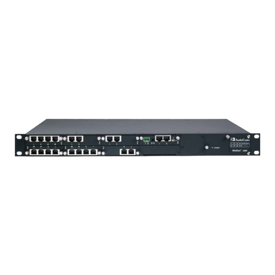
Page 12: Front Panel
Mediant 1000 2.1.1 Front Panel The device's front panel is shown in the figure below and described in the subsequent table. Figure 2-1: Front-Panel View and CPU Enlargement Table 2-1: Front Panel Component Descriptions Label/ Component Description Item # Module (Optional) FXO and FXO G module (applicable only to SIP): The device can house up to six FXO modules. - Page 13 Installation Manual 2. Installing the Device Label/ Component Description Item # Module (Optional) Media Processing Module (MPM): The device supports up to three MPM modules for IP media server capabilities (i.e., conferencing, SBC, and IP-to-IP routing applications). These modules can be housed in slots 3, 4, 5, or 6, depending on required configuration (for a detailed description of channel resources using MPM modules, refer to the device's User's Manual).
-
Page 14: Rear Panel
Four anti-slide bumpers for desktop installation option. • Two-meter length RS-232 DB-9 adaptor cable (for direct serial connection to PC). Check, retain and process any documents. Notify AudioCodes or your local supplier of any damage or discrepancies. Installation Manual Document #: LTRT-83505... -
Page 15: Mounting The Device
Installation Manual 2. Installing the Device Mounting the Device The device can be mounted in one of the following ways: Placed on a desk top (refer to 'Desktop Mounting' on page 15) Installed in a standard 19-inch rack (refer to 'Installing the Device in a 19-inch Rack' on page 16) 2.3.1 Desktop Mounting... -
Page 16: Installing The Device In A 19-Inch Rack
Mediant 1000 Peel off the adhesive, anti-slide rubber feet and stick one in each anti-slide groove. Figure 2-5: Peeled-off Rubber Foot Flip the device over again so that it rests on its underside and place it in the required position on a desktop. - Page 17 Installation Manual 2. Installing the Device To mount the device on a pre-installed shelf in the rack: Place the device on a pre-installed shelf in the rack. It's recommended to attach the device's integral front mounting brackets to the rack's frame to prevent it from sliding off the shelf during cabling.
-
Page 18: Cabling The Device
Mediant 1000 Cabling the Device This section describes the cabling of the device, which includes the following: Connecting to earth/ground (refer to 'Earthing (Grounding) the Device' on page 18) Protective Earthing The equipment is classified as Class I EN60950 and UL60950 and must be earthed at all times. -
Page 19: Connecting To Earth (Ground)
Installation Manual 2. Installing the Device 2.4.1 Connecting to Earth (Ground) The device must be permanently connected to earth (ground), using an equipment-earthing conductor. Protective Earthing The equipment is classified as Class I EN60950 and UL60950 and must be earthed at all times. To earth the device: Connect an electrically earthed strap of 16 AWG wire (minimum) to the chassis' earthing screw (located on the rear panel), using the supplied washer. -
Page 20: Connecting To Fxs/Fxo Interfaces
Mediant 1000 2.4.3 Connecting to FXS/FXO Interfaces The procedure below describes the cabling of the device's FXS and FXO module analog interfaces. Warnings: • To protect against electrical shock and fire, use a 26 AWG min wire to connect FXO ports to the PSTN. -
Page 21: Figure 2-8: Rj-11 Connector Pinouts For Fxs Lifeline
The Lifeline splitter connects pins 1 and 4 to another source of an FXS port, and pins 2 and 3 to the POTS phone, as shown in the figure below. Figure 2-8: RJ-11 Connector Pinouts for FXS Lifeline Figure 2-9: Mediant 1000 Analog Lifeline Cable Setup Table 2-3: FXS Lifeline Setup Component Descriptions Item # Component Description Lifeline phone. -
Page 22: Connecting To Isdn Bri Lines
Mediant 1000 2.4.5 Connecting to ISDN BRI Lines The device can house up to five BRI modules, each supporting four BRI ports, thereby providing a total of up to 20 BRI ports. Note: BRI interface is applicable only to devices running the SIP protocol. -
Page 23: Connecting To E1/T1 Trunks For Pstn Fallback
Trunk from the PBX is routed from the module to the PSTN. Figure 2-12: Mediant 1000 Digital Lifeline Cabling (e.g., Trunks 1 and 2) To connect the digital trunk interfaces for 1+1 or 2+2 PSTN Fallback: On the same TRUNKS module, connect Trunk 1 and Trunk 3 to your PBX, and Trunk 2 and Trunk 4 to the PSTN. -
Page 24: Connecting To Dry Contact Relay Alarm System
Mediant 1000 2.4.8 Connecting to Dry Contact Relay Alarm System The dry contact ports I and II located on the device's CPU module, allows you to connect the device to an external audible or visual alarm system. The table below describes the operational status of these dry contact ports. -
Page 25: Connecting Rs-232 Serial Interface To Pc
Installation Manual 2. Installing the Device To set up a dry contact system: Insert two wires into the mate’s spring-cage wire connectors in position 4 and 3 for the device's dry contact Port I, and two wires in position 2 and 1 (for the device's dry contact Port II), by performing the following: With a sharp, pointed object, press the position's corresponding orange button;... -
Page 26: 2.4.10 Connecting To Power
Mediant 1000 2.4.10 Connecting to Power The device can house up to two extractable power supply modules (Power 1 and Power 2), each providing an AC power connector on the device's rear panel. The dual power option provides the device with power redundancy. -
Page 27: Maintenance
(I/O) interface modules (i.e., TRUNKS, BRI, FXS, FXO, and MPM). Figure 2-16: Mediant 1000 Front Layout The guidelines for slot assignment for these modules, include the following: The TRUNKS, BRI, FXS, and FXO modules must be housed in consecutive slots. In other words, if the device houses three modules, then they must occupy slots 1, 2, and 3 (no skipping of slots). -
Page 28: Replacing Modules
Mediant 1000 For example, if the device requires one TRUNKS module and two FXS modules, then you must insert the TRUNKS module in Slot 1 and the two FXS modules in slots 2 and 3 respectively. If at a later stage, you wish to add a BRI module (for example), then you must replace the FXS module in Slot 2 with the new BRI module, and then re- insert this replaced FXS module in Slot 4. -
Page 29: Figure 2-18: Module Orientation In Chassis Top- And Bottom-Row Slots
Installation Manual 2. Installing the Device To replace I/O modules: Software-remove the module, using the device's Web interface's 'Home' page (refer to the device's User's Manual). Disconnect the cables from the module that you want to replace. Physically remove the module from the device's front-panel slot, by performing the following: Using a flathead screwdriver, loosen the module's two mounting screws. -
Page 30: Inserting Modules Into Previously Empty Slots
Mediant 1000 2.5.3 Inserting Modules into Previously Empty Slots The procedure below describes how to add additional I/O modules to previously empty slots in the device's chassis. Warning: Ensure that you power down the device before adding a module to a previously empty slot. -
Page 31: Figure 2-19: Slightly Extracted Fan Try Unit
Installation Manual 2. Installing the Device Warnings: • When removing the Fan Tray module while the power is on (or after it has recently been switched off), the blades may still be rotating at high speeds. Therefore, to avoid bodily harm ensure that you don't touch the fan blades. - Page 32 Mediant 1000 Take one of the following steps: • If you are cleaning the filter, use a vacuum cleaner (set to light suction) to remove dust particles from the filter. • If you are replacing the filter, discard the old air filter and replace it with an air filter purchased from AudioCodes.
-
Page 33: Configuring The Device
Installation Manual 3. Configuring the Device Configuring the Device This section describes initial, basic setup configuration for the device, using the device's embedded Web server (Web interface). Notes: • The device is supplied with application software (cmp file) already residing on its flash memory. This software is set to factory defaults. •... -
Page 34: Assigning An Ip Address Using Http
Mediant 1000 3.1.1 Assigning an IP Address using HTTP You can assign an IP address to the device, using the device's Web interface. To assign an IP address using HTTP: Disconnect the device from the network and reconnect it to a PC using one of the following methods: •... -
Page 35: Assigning An Ip Address Using Bootp
PC and re-access the device via the Web interface with its newly assigned IP address. 3.1.2 Assigning an IP Address using BootP You can assign an IP address to the device, using the supplied AudioCodes' BootP/TFTP Server application. Notes: •... -
Page 36: Assigning An Ip Address Using The Voice Menu Guidance
Mediant 1000 Click Apply to save the new client. Click OK; the ‘Client Configuration’ screen closes. Physically reset the device using the hardware reset button (or power down and then power up the device). This causes the device to use BootP; the device changes its network parameters to the values provided by BootP. - Page 37 Installation Manual 3. Configuring the Device To change the IP address: Press 1 followed by the pound key (#); The current IP address of the device is played. Press the # key. Dial the new IP address. Use the star (*) key instead of periods (.), e.g., 192*168*0*4, and then press # to finish.
-
Page 38: Table 3-2: Configuration Parameters Available Via The Voice Menu
Mediant 1000 Dial 32 followed by the # key, and then perform the following to change the configuration file name pattern: Press the # key. Select one of the patterns listed in the table below (aa.bb.cc.dd denotes the IP address of the configuration server):... -
Page 39: Assigning An Ip Address Using The Cli
Installation Manual 3. Configuring the Device Item Number at Description Menu Prompt Primary DNS server IP address. DHCP enable / disable. Configuration server IP address. Configuration file name pattern. Voice menu password (initially 12345). Note: The voice menu password can also be changed using the Web interface or ini file parameter VoiceMenuPassword (refer to the User's Manual). -
Page 40: Configuring Basic Sip Parameters
Mediant 1000 Configuring Basic SIP Parameters Once you have completed the previous sections, you are ready to start configuring the device using the Web interface. For information on how to fully configure the device, refer to the device's User’s Manuals. -
Page 41: Configuring Basic Mgcp/Megaco Parameters
Installation Manual 3. Configuring the Device Configuring Basic MGCP/MEGACO Parameters Once you have completed the previous sections, you are ready to start configuring the device using the Web interface. For information on how to fully configure the device, refer to the device's User’s Manuals. -
Page 42: Enabling Channels And Configuring Call Routing (Example)
Mediant 1000 For MGCP take the following steps: In the ‘SDP Session Owner’ field, enter a name to the device (for example, ‘gateway1.com’). Ensure that the name you choose is the one that the Call Agent is configured with to identify your device. -
Page 43: Figure 3-4: Routing Tel Calls To An Ip Address In Tel To Ip Routing Page
Installation Manual 3. Configuring the Device Assign telephone numbers to the following interfaces: ♦ FXS (only SIP): In the 'Module' column, select 'Module 3 FXS', enter 1-4 (i.e., channels 1 through 4) in the ‘Channel(s)’ column, and then in the 'Phone Number' column, enter the phone number (e.g., 101) for the first channel. -
Page 44: Configuring Pstn Trunks
Mediant 1000 Configuring PSTN Trunks This section describes how to configure the configure the device's E1/T1 PRI and BRI trunks. To configure the trunks: Open the ‘Trunk Settings’ page (Configuration tab > PSTN Settings menu > Trunk Settings). Figure 3-5: Trunk Settings Page... - Page 45 Installation Manual 3. Configuring the Device From the ‘Framing Method’ drop-down list, select the required framing method. For E1 trunks, always set this parameter to ‘Extended Super Frame’. From the ‘Clock Master’ drop-down list, select the trunk's clock source: • ‘Recovered’...
-
Page 46: Saving And Resetting The Device
Mediant 1000 Saving and Resetting the Device To apply configuration changes to the device's volatile memory (RAM), click the Submit button located on the page in which you are configuring. Modifications to parameters with on-the-fly capabilities are immediately applied to the device; other parameters are applied only after a device reset. -
Page 47: Changing Login User Name And Password
For detailed information on the Web user accounts, refer to the device's User’s Manual. Tip: If you do not know your user name and password, you can use AudioCodes BootP/TFTP utility to access the device, by re-flash the load and resetting the password (refer to the Product Reference Manual). -
Page 48: Backing Up And Restoring Configuration
Mediant 1000 Backing Up and Restoring Configuration You can save a copy/backup of the device's current configuration settings (Voice) as an ini file to a folder on your PC, using the 'Configuration File' page. The saved ini file includes only parameters that were modified and parameters with other than default values. The 'Configuration File' page also allows you to load an ini file to the device. -
Page 49: Restoring Factory Default Settings
Installation Manual 3. Configuring the Device To load (or restore) the ini file: Click the Browse button, navigate to the folder in which the ini file is located, select the file, and then click Open; the name and path of the file appear in the field beside the Browse button. -
Page 50: Upgrading The Device
Mediant 1000 3.10 Upgrading the Device You can upgrade the device with the following files, using the device's Web interface: Firmware (cmp) file using the Web interface's Software Update Wizard (refer to 'Software Upgrade Wizard' on page 50). Auxiliary and ini files using the 'Load Auxiliary Files' page (refer to 'Upgrading the ini and Auxiliary Files' on page 53). -
Page 51: Figure 3-9: Start Software Upgrade Wizard Screen
Installation Manual 3. Configuring the Device Notes: • Before you can load an ini or any auxiliary file, you must first load a cmp file. • When you activate the wizard, the rest of the Web interface is unavailable. After the files are successfully loaded, access to the full Web interface is restored. -
Page 52: Figure 3-10: Load Cmp File Wizard Page
Mediant 1000 Figure 3-10: Load CMP File Wizard Page Note: At this stage, you can quit the Software Update Wizard, by clicking Cancel , without requiring a device reset. However, once you start uploading a cmp file, the process must be completed with a device reset. -
Page 53: Figure 3-11: End Process Wizard Page
Installation Manual 3. Configuring the Device You can now choose to either: • Click Reset; the device resets, utilizing the new cmp and ini file you loaded up to now as well as utilizing the other auxiliary files. • Click Back; the 'Load a cmp file' page is opened again. •... -
Page 54: 3.10.2 Loading Ini And Auxiliary Files
Mediant 1000 3.10.2 Loading ini and Auxiliary Files The auxiliary files (and ini file) are dat files that can be loaded to the device to provide enhanced device provisioning. These files are described in the table below. For detailed information on these files, refer to the device's User's Manual. -
Page 55: Figure 3-12: Load Auxiliary Files Page
Installation Manual 3. Configuring the Device To load an auxiliary file to the device: Open the 'Load Auxiliary Files' page (Management tab > Software Update menu > Load Auxiliary Files). Figure 3-12: Load Auxiliary Files Page Click the Browse button corresponding to the file type that you want to load, navigate to the folder in which the file is located, and then click Open;... - Page 56 Mediant 1000 Reader’s Notes Installation Manual Document #: LTRT-83505...
-
Page 57: Monitoring The Device
Installation Manual 4. Monitoring the Device Monitoring the Device The operating status of the device can be monitored in the following ways: Monitoring the device's hardware front-panel LEDs (refer to 'Front-Panel LEDs' on page 57). Monitoring the device using the Web interface (refer to 'Web Interface' on page 58). Front-Panel LEDs The location of the device's front panel LEDs are shown in the figure below and described in the subsequent table. -
Page 58: Web Interface
Mediant 1000 Table 4-3: BRI I/O Modules LED Description (Applicable only to SIP) Color State Description RJ-45 Green Physical layer (Layer 1) is synchronized (normal operation). Physical layer (Layer 1) is not synchronized. Trunk is not active. Table 4-4: Power Supply Module LED Description... -
Page 59: Viewing Alarms
Installation Manual 4. Monitoring the Device 4.2.1 Viewing Alarms The 'Home' page allows you quick access to the 'Active Alarms' page (typically accessed from the Status & Diagnostics tab > Status & Diagnostics menu > Active Alarms). This page lists all the device's current alarms. To view a list of current alarms: In the 'Home' page, click the area labeled Alarms;... -
Page 60: Viewing Channel Status
You can use these port icons to drill down to view detailed channel status. For a detailed description of the 'Home' page, refer to the device's User's Manual. Figure 4-3: Mediant 1000 Web Interface’s Home Page Table 4-6: Color-Coding of Trunk / Channel Status Icon... - Page 61 Installation Manual 4. Monitoring the Device Reader’s Notes Version 5.8 June 2009...
- Page 62 Installation Manual Version 5.8 www.audiocodes.com...