AudioCodes Mediant 1000 User Manual
Voip digital media gateways megaco, tpncp
Hide thumbs
Also See for Mediant 1000:
- User manual (1195 pages) ,
- Hardware installation manual (84 pages) ,
- Installation manual (76 pages)

Subscribe to Our Youtube Channel
Related Manuals for AudioCodes Mediant 1000


Summary of Contents for AudioCodes Mediant 1000
- Page 1 ™ VoIP Digital Media Gateways Mediant 1000 MEGACO, TPNCP User’s Manual version 5.2...
-
Page 3: Table Of Contents
Installing the Mediant 1000 in a 19-inch Rack........38 3.1.4 Cabling the Mediant 1000................ 39 3.1.4.1 Connecting the Mediant 1000 RS-232 Port to Your PC ..... 40 3.1.4.2 Setting up a Dry Contact Relay Alarm System........41 3.1.4.3 Connecting the Audio IN/OUT Cable..........42 Software Package....................45... - Page 4 Mediant 1000 5.1.2 Assigning an IP Address Using BootP............. 50 5.2 Restoring Networking Parameters to their Initial State......50 Mediant 1000 Initialization & Configuration Files ...........53 6.1 Boot Firmware & Operational Firmware ..........53 6.2 Mediant 1000 Startup ................53 6.3 Using BootP/DHCP..................55 6.3.1...
- Page 5 Defining Field Width in the Termination Name......... 111 7.1.8.5 Termination Mapping to a PSTN Interface ........112 7.1.9 7.1.10 H.248.1 V2 - Main Changes ..............114 Mediant 1000 Management................117 8.1 Command-line Interface................117 8.1.1 Starting a CLI Management Session ............. 117 8.1.2 CLI Navigation Concepts ...............118...
- Page 6 Limiting Web Access to a Predefined List of Client IP Addresses ... 173 8.3.2.5 Managing Web Server Access Using a RADIUS Server....173 8.3.3 Correlating PC / Mediant 1000 IP Address & Subnet Mask ....173 8.3.4 Accessing the Embedded Web Server ..........174 8.3.5 Using Internet Explorer to Access the Embedded Web Server .....
- Page 7 User's Manual Contents 8.4 From the gateway HomePage you can : ..........176 8.4.1.1.1 Main Menu Bar ............182 8.4.1.1.2 Search Engine ............182 8.4.1.1.3 Port Information ............184 8.4.1.1.4 Channel Status Screens......... 185 8.4.1.2 Quick Setup ..................186 8.4.2 Protocol Management................188 8.4.2.1 Protocol Selection................
- Page 8 Mediant 1000 8.4.7 Maintenance ..................256 8.4.7.1 Reset Button ..................257 8.4.7.2 Lock / Unlock ..................258 8.4.7.3 Save Configuration ................258 8.4.8 Restoring and Backing Up the Device Configuration......259 8.4.9 Voice Menu....................260 Diagnostics & Troubleshooting ..............263 9.1 Syslog.....................263 9.1.1 Operating the Syslog Server..............
- Page 9 User's Manual Contents 14.1.2.1.1 Default Template for Call Progress Tones ..... 376 14.1.3 Modifying the Call Progress Tones File ..........379 14.1.4 Converting a Modified CPT ini File to a dat File with the Download Conversion Utility .................380 14.2 Playing the Prerecorded Tones (PRT) Auxiliary File ......380 14.2.1 PRT File Configuration ................
- Page 10 Mediant 1000 17.5.5 DTMF/MF Oriented Events..............404 17.5.6 Operator Service Events (up to GR-506)..........406 17.6 Function ....................407 17.7 Parameters .....................408 17.8 Next State ....................410 17.9 Changing the Script File ...............411 17.9.1 MFC R2 Protocol ................... 411 17.10 Changing the ST_INIT Parameter Values Off Line (No Compilation)413 18 Appendix - Security..................415...
- Page 11 23.3 Replacing the Background Image File..........502 23.4 Customizing the Product Name ............503 23.4.1 Customizing the Web Browser Title Bar ..........504 24 Appendix - Mediant 1000 OSN Server Hardware Installation ......505 24.1 Required Working Tools ...............505 24.2 OSN Server Installation on the Mediant 1000........505 25 Appendix - Linux™...
- Page 12 Mediant 1000 25.3 Software Installation ................514 25.4 Linux™ RedHat (and Fedora) Installation Instructions ......514 25.4.1 Stage 1: Obtaining the ISO Image............515 25.5 Downloading an Updated Linux™ Redhat ISO Image......515 25.6 Creating an Updated Linux™ Redhat ISO Image........515 25.7 Stage 2: Editing the isolinux.cfg File ...........517 25.7.1 Stage 2: Editing the isolinux.cfg File............
- Page 13 Contents List of Figures Figure 1-1: Typical Mediant 1000 Wireline Application ................24 Figure 2-1: Mediant 1000 Front View & CPU Enlargement..............25 Figure 2-2: CPU Module.........................33 Figure 2-3: Digital 1/O Module .......................33 Figure 2-4: Fan Tray Module with 3 Fans ....................33 Figure 2-5: Power Supply Modules ......................33...
- Page 14 Mediant 1000 Figure 8-39: Application Settings Screen .................... 202 Figure 8-40: NFS Settings Table Screen .................... 203 Figure 8-41: Routing Table Screen ..................... 204 Figure 8-42: VLAN Settings Screen ....................205 Figure 8-43: SCTP Settings......................... 206 Figure 8-44: Voice Settings Screen..................... 206 Figure 8-45: RTP Settings Screen (Network Settings)................
- Page 15 Figure 24-4: Mediant 1000 Front Panel View..................507 Figure 24-5: Inserting the CM Module....................508 Figure 24-6: Mediant 1000 Rear Panel View..................508 Figure 24-7: Mediant 1000 with Cover Plates Removed..............509 Figure 24-8: Mediant 1000 with Cutter Tool ..................509 Figure 24-9: Inserting OSN Server Module ..................
- Page 16 Table 2-1: Mediant 1000 Front View Component Descriptions..............26 Table 2-2: Mediant 1000 Front Panel.....................26 Table 2-3: Functionality of the Front Panel LEDs ..................28 Table 2-4: Mediant 1000 Rear Connectors Component Descriptions ...........32 Table 3-1: Dry Contact Operational Description ..................41 Table 3-2: Audio Levels..........................42 Table 4-1: Software Package Contents....................46...
- Page 17 User's Manual Contents Table 14-1: Default Call Progress Tones .................... 377 Table 14-2: Aliases Used for Currently Supported Coders ..............383 Table 15-1: Payload Types Defined in RFC 3551................389 Table 15-2: Payload Types Not Defined in RFC 3551 ................ 389 Table 15-3: Dynamic Payload Types Not Defined in RFC 3551 ............
-
Page 19: Introductory Notes
Notice This User’s Manual describes the installation and use of the Mediant 1000. Information contained in this document is believed to be accurate and reliable at the time of printing. However, due to ongoing product improvements and revisions, AudioCodes cannot guarantee the accuracy of printed material after the Date Published nor can it accept responsibility for errors or omissions. -
Page 20: Abbreviations And Terminology
(for example various networking issues). VoPLib API Reference Manual, Document # LTRT-840xx - intended for users, who wish to control the blade via the AudioCodes VoPLib API (over PCI or TPNCP). This manual is a documentation browser in HTML or CHM formats (created from the VoPLib documented source files). -
Page 21: Overview Of The Mediant 1000
PBX systems to IP networks, as well as seamless connection of the IP-PBX to the PSTN. In addition to operating as a pure media gateway, the Mediant 1000 can also host partner applications and serve as an IP-PBX platform. The Mediant 1000 is fully interoperable with multiple vendor gateways, Softswitches, gatekeepers, proxy servers, IP phones, session border controllers and firewalls. -
Page 22: Supported Protocols
MF-R1, MFC-R2 and Call Progress Tone detection and generation Management Interfaces: SNMP V2, Embedded Web Server Mounting option of installing two Mediant 1000 Gateways in a single 19-inch rack shelf, 1 U high (1.75" or 44.5 mm) Optional dual redundant AC power supplies 1.1.1... -
Page 23: Management Protocols
TFTP BootP - Refer to Appendix - BootP/TFTP Server RS-232 for basic configuration and debugging Mediant 1000 Applications The Mediant 1000 can be used in a variety of applications, which exploit its unique advantages regarding compressing PCM voice channels to IP packets according to ITU and IETF standards. -
Page 24: Typical Application Diagram
Mediant 1000 Typical Application Diagram The diagram below illustrates a typical wireline application. Figure 1-1: Typical Mediant 1000 Wireline Application PABX PSTN Telephone Telephone Telephone Telephone 4 E1/T1 Telephone Telephone Telephone Mediant 1000 Mediant 1000 Telephone/Fax Router Internet Router Telephone... -
Page 25: Hardware Equipment
1000 is a 19-inch industrial platform chassis, 1U high and 13.8 inch deep. The Mediant 1000 supports a scalable, modular architecture that includes up to four digital modules, a single CPU module, a power supply module and an optional fan try module (the extractable modules are shown in Table ý2 4 on page 34). -
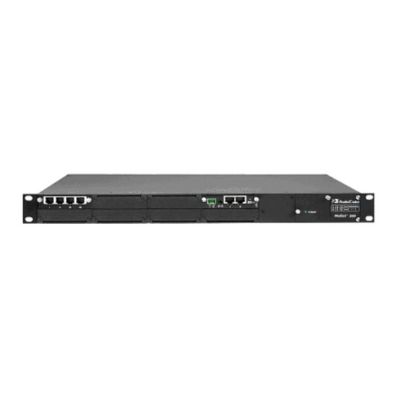
Page 26: Table 2-1: Mediant 1000 Front View Component Descriptions
Dry Contact port for alarm application. Locking Screw (2). The table below illustrates the front layout of the Mediant 1000. There is also a schematic of the front layout on the front panel of the fan tray. To view your specific device's configuration use the Embedded Web Server. -
Page 27: I/O Modules
2.1.3.2 Audio IN/OUT The Audio IN/OUT port is indicated by the musical note and loudspeaker symbols (refer to the figure in Mediant 1000 Front Panel on page 25). It is used for Music on Hold (IN) and paging (OUT). 2.1.3.3... -
Page 28: Power Supply Module (Labeled 1 And 2)
The front panel of the power supply unit features a power supply LED that is lit green when the Mediant 1000 is powered up. If this LED does not light up, a power supply problem may be present. -
Page 29: Fan Tray Module (Optional)
The incoming air passes through a removable filter, whose honeycombed design prevents RF interference. The clean air passes through the entire set of modules cooling each one and exits the Mediant 1000 via perforated vents on the left side of the chassis. -
Page 30: Replacing The Air Filter
Mediant 1000 Note: It is imperative to cover all unoccupied slots in the front and rear panels of the chassis with blank panels to maintain internal airflow pressure. 2.1.6.1 Replacing the Air Filter The fan try module includes a removable air filter (located within the fan assembly, immediately inside the perforated grill). -
Page 31: Mediant 1000 Rear Panel
Fasten the two screws on the top right-hand corner and the bottom right-hand corner of the front panel of the fan tray unit. 2.1.7 Mediant 1000 Rear Panel The Mediant 1000 rear connectors are described in the following sections (refer to the figure below). Version 5.2 July 2007... -
Page 32: Mediant 1000 Modules
Used for ESD (Electrostatic Discharge) protection when removing or inserting modules from or into the Mediant 1000. Protective earthing screw. 100-240v~1A Dual AC Power Supply Entry. 2.1.8 Mediant 1000 Modules The extractable Mediant 1000 modules are shown in the figures below. User's Manual Document # LTRT--66405... -
Page 33: Figure 2-2: Cpu Module
User's Manual 2. Hardware Equipment Figure 2-2: CPU Module Figure 2-3: Digital 1/O Module Figure 2-4: Fan Tray Module with 3 Fans Figure 2-5: Power Supply Modules Version 5.2 July 2007... -
Page 34: Figure 2-6: Mediant 1000 Media Process Module
Mediant 1000 Figure 2-6: Mediant 1000 Media Process Module User's Manual Document # LTRT--66405... -
Page 35: Mediant 1000 Lifeline Phone Link
2.1.9 Mediant 1000 Lifeline Phone Link The Mediant 1000 with either one or two modules, each with 1 or 2 pairs of spans can provide a "Lifeline" telephone link. In the event of power failure, a link is provided by the closing of a metallic switch in the module so that the trunk from the PBX is routed out of the module to the PSTN. -
Page 37: Hardware Installation
Cable the Mediant 1000 (refer to Cabling the Mediant 1000 on page 39). After connecting the Mediant 1000 to the power source, the power LED on the front panel of the power supply unit is lit green (after a self-testing period of about 2 minutes). -
Page 38: Mounting The Mediant 1000
3.1.3.2 Installing the Mediant 1000 in a 19-inch Rack Users can install the Mediant 1000 in a standard 19-inch rack either by placing it on a shelf pre-installed in the rack (preferred method), or by attaching it directly to the rack’s frame. -
Page 39: Cabling The Mediant 1000
Connect the first Ethernet connection (labeled I), located on the CPU module of the Mediant 1000 front panel, directly to the network using a standard RJ-45 Ethernet cable (and the second connection as optional redundancy / backup). -
Page 40: Connecting The Mediant 1000 Rs-232 Port To Your Pc
Optionally, connect the Mediant 1000 RS-232 port to your PC (refer to Connecting the Mediant 1000 RS-232 Port to Your PC on page 40) for debugging and system monitoring only. -
Page 41: Setting Up A Dry Contact Relay Alarm System
Table (refer to Gateway HomePage on page 176) in the gateway's embedded Web server. The external alarm system is connected to the Mediant 1000 gateway's dry contact connector on the CPU module, using the supplied dry contact wires’ mate (refer to the figure below). -
Page 42: Connecting The Audio In/Out Cable
Mediant 1000 Note: The Dry Contact alarm provided on the CPU card should be connected only to SELV (Safety Extra-Low Voltage) non-energy hazard sources (Class 2) as per UL60950 and EN60950. To set up a Dry Contact system, take these 2 steps: Insert two wires into the mate’s spring-cage wire connectors in position 4 and 3... -
Page 43: Figure 3-5: Audio Cable And In/Out Rca Connectors
User's Manual 3. Hardware Installation Figure 3-5: Audio Cable and IN/OUT RCA Connectors Version 5.2 July 2007... -
Page 45: Software Package
This software package must be installed on the host PC/machine to be used to manage the device. The software package is supplied to customers on a CD accompanying the Mediant 1000. To get started, take these basic steps: To install the software package refer to the Installing/Unzipping instructions below. -
Page 46: Unzipping When Using A Linux™/Solaris™ Operating System
PCI mode. When the device is supplied to customers, it is already configured with pre-installed firmware. AudioCodes’ utilities provide you with friendly interfaces that enhance device Utilities usability and smooth your transition to the new VoIP infrastructure. Contains the TrunkPack .\Utilities\DConvert... - Page 47 User's Manual 4. Software Package Table 4-1: Software Package Contents Contents Directory Description dissection of AudioCodes' proprietary protocol. All relevant product documentation Documentation All the demo programs described above are for reference only. Flawless Note: operation and stability of these applications can not be guaranteed.
-
Page 49: Getting Started
169. Assigning the Mediant 1000 IP Address To assign an IP address to the Mediant 1000 use one of the following methods: HTTP using a Web browser (refer to 'Assigning an IP Address Using HTTP' on page 49). -
Page 50: Assigning An Ip Address Using Bootp
If your network doesn’t feature a default gateway, enter a dummy value in the Default Gateway IP Address field. Click the Reset button and click OK in the prompt. The Mediant 1000 applies the changes and restarts. This takes approximately 1 minute to complete. When the Mediant 1000 has finished restarting, the Ready and LAN LEDs on the front panel are lit green. - Page 51 While the Control LED is blinking, use a paper clip to press shortly on the reset button (located next to the AudioCodes logo on the front panel). The gateway resets a second time and is restored with factory default parameters (username: Admin, password: Admin - both case-sensitive).
-
Page 53: Mediant 1000 Initialization & Configuration Files
CD accompanying the Mediant 1000. This file contains the Mediant 1000's main software, providing all the services described in this manual. The cmp file is usually burned into the Mediant 1000's non-volatile memory so that it does not need to be externally loaded each time the Mediant 1000 is reset. -
Page 54: Figure 6-1: Startup Process Diagram
Mediant 1000 Users perform a reset in the Embedded Web Server GUI or SNMP manager. The flow chart in the figure below illustrates the process that occurs in these scenarios. Figure 6-1: Startup Process Diagram Reset command from Web interface,... -
Page 55: Using Bootp/Dhcp
'Using BootP/DHCP' on page 55. Using BootP/DHCP The Mediant 1000 uses the Bootstrap Protocol (BootP) and the Dynamic Host Configuration Protocol (DHCP) to obtain its networking parameters and configuration automatically after it is reset. BootP and DHCP are also used to provide the IP address of a TFTP server on the network, and files (cmp and ini) to be loaded into memory. -
Page 56: Command Line Switches
When the Mediant 1000 detects that this optional parameter field is defined in BootP, it initiates a TFTP process to load the file into the Mediant 1000. The new configuration contained in the ini file can be stored in the Mediant 1000's integral non-volatile memory. -
Page 57: Host Name Support
"AUDC". Refer to Selective BootP on page 58. Use -be 1 for the Mediant 1000 to send client information that can be viewed in the main screen of the BootP/TFTP Server, under column 'Client Info‘ (refer to the figure, Main Screen, with the column 'Client Info' on the extreme right). -
Page 58: Selective Bootp
DHCP request. The host name is set to ACL_nnnnnnn, where nnnnnnn is the serial number of the Mediant 1000 (the serial number is equal to the last 6 digits of the MAC address converted from Hex to decimal). The DHCP server usually registers this Host Name on the DNS server. -
Page 59: Microsoft™ Dhcp/Bootp Server
Microsoft™ DHCP/BootP Server The Mediant 1000 can be configured with any BootP server, including the Microsoft™ Windows™ DHCP server, to provide the Mediant 1000 with an IP address and other initial parameter configurations. To configure the Microsoft™ Windows™ DHCP Server to configure an IP address to BootP clients, add a reservation for each BootP client. -
Page 60: Initialization (Ini) File
Call Progress Tones, Voice Prompts, logo image, etc. These files contain factory-pre-configured parameter defaults when supplied with the Mediant 1000 and are stored in the Mediant 1000's non-volatile memory. The Mediant 1000 is started up initially with this default configuration. Subsequently, these files can... -
Page 61: Parameter Value Structure
User's Manual 6. Mediant 1000 Initialization & Configuration Files Format Index_Name_1 ... Index_Name_N = Param_Name_1 ... Param_Name_M ; Table's Lines (repeat for each line) Table_Name Index_1_val ... Index_N_val = Param_Val_1 ... Param_Val_M [\Table_Name] 6.4.1.1 Parameter Value Structure The following are the rules in the ini File structure for individual ini file parameters (Parameter = Value): Lines beginning with a semi-colon ';' (as the first character) are ignored. -
Page 62: Tables Of Parameter Value Structure
; 1 - for version 2, 2 - for version 1. MGCPCOMPATIBILITYPROFILE = 2 Before loading an ini file to the Mediant 1000, make sure that the extension Note: of the ini file saved on your PC is correct: Verify that the checkbox Hide extension for known file types (My Computer>Tools>Folder Options>View) -
Page 63: Table 6-4: Table Structure Example
User's Manual 6. Mediant 1000 Initialization & Configuration Files FORMAT SS7_SIG_IF_ID_INDEX = SS7_SIG_IF_ID_VALUE, SS7_SIG_IF_ID_NAME, SS7_SIG_IF_ID_OWNER_GROUP, SS7_SIG_IF_ID_LAYER, SS7_SIG_IF_ID_NAI, SS7_SIG_M3UA_SPC; SS7_SIG_INT_ID_TABLE 1 = 101, AMSTERDAM1, 3, 3, 1, 4; SS7_SIG_INT_ID_TABLE 5 = 100, BELFAST12, 3, 3, 0, 11; [ \SS7_SIG_INT_ID_TABLE ] The table below is shown in document format for description purposes:... -
Page 64: Tables In The Uploaded Ini File
Mediant 1000 defined default value for each configured line. • The order of the Data fields in the Format line is not significant (unlike the Index-fields). Field values in Data lines are interpreted according to the order specified in the Format line. -
Page 65: Binary Configuration File Download
The ini file to be loaded and retrieved is available with or without encoding. When an encoded ini file is downloaded to the Mediant 1000, it is retrieved as encoded from the Mediant 1000. When a decoded file is downloaded to the Mediant 1000, it is retrieved as decoded from the Mediant 1000. -
Page 66: Automatic Update Facility
[AuxilaryFileType]FileName. This parameter takes the name of the auxiliary file to be downloaded to the Mediant 1000. If the ini file does not contain a parameter for a specific auxiliary file type, the Mediant 1000 uses the last auxiliary file that was stored on the non-volatile memory. - Page 67 The Automatic Update process is entirely controlled by configuration parameters in the ini file. During the Automatic Update process, the Mediant 1000 contacts the external server and requests the latest version of a given set of URLs. An additional benefit of using HTTP (Web) servers is that configuration ini files would be downloaded only if they were modified since the last update.
-
Page 68: Backup Copies Of Ini And Auxiliary Files
RESETNOW = 1 You may modify the master_configuration.ini file (or any of the config_<MAC>.ini files) at any time. The Mediant 1000 queries for the latest version every 60 minutes, and applies the new settings immediately. For additional security, usage of HTTPS and FTPS protocols is recommended. -
Page 69: Software Upgrade Key
6.6.1 Software Upgrade Key The Software Upgrade Key is a string stored in the Mediant 1000's non-volatile flash memory, defining the features and capabilities allowed by the specific license purchased by the customer. Customers specify the features and capabilities they require at the time they order the device. -
Page 71: Standard Control Protocols
AudioCodes’ version 5.2 supports V2 and is backward compatible with V1. Since this is a standards-based control protocol, AudioCodes does not provide or require the customer to use any specific software library in order to construct a Call Agent. (Customers may choose any of many such stacks available in the market.) -
Page 72: Operation
Notify command - The Notify command is used by the Mediant 1000 to inform the Call Agent of events occurring on one of the Terminations. -
Page 73: Setting Megaco Call Agent Ip Address And Port
The first Call Agent in the list is the primary one. In the case of a loss of connection, the Mediant 1000 tries to connect with the next on the list, and it continues trying until one of the Call Agents accepts the registration request. If the current connection is with a secondary MGC, the Mediant 1000 starts again from the primary MGC. -
Page 74: Support Of Diffserv Capabilities
Mediant 1000 7.1.2.6 Support of DiffServ Capabilities The DiffServ value of the IP header can be set for both the control path and the media path. The range of the DiffServ parameter is between 0 and 63. It enables routers to differentiate between different streams. -
Page 75: Table 7-2: Signal Combination Options For Cas Support
User's Manual 7. Standard Control Protocols Table 7-1: General Signal Combination Options Group 1 Notes Group 2 Notes blade andisp/* (cpSignal) Only when analog gb/* (3G) blade aasb/* (cpSignal) Including all the bt/* (3G) inheriting packages nttrk/* (cpSignal) ctyp/* Table 7-2: Signal Combination Options for CAS Support Group 1 Notes Group 2... -
Page 76: Megaco Supported Signals
MEGACO when playing the signal. For the correlation between signal names and CPT file IDs, refer to the column, Map to CPT File of the table below. When a CPT file is missing, the Mediant 1000 defines default values only for the following signals: Dial tone... - Page 77 User's Manual 7. Standard Control Protocols MEGACO Supported Signals Symbol Definition Type Duration Map to CPT File cg/sit Special Information 2 sec tone cg/wt Warning tone 1sec cg/pt Payphone 180 sec Recognition tone cg/cw Call Waiting tone 1 sec cg/cr Caller Waiting tone 180 sec xcg/cmft...
-
Page 78: Mediation
Mediant 1000 MEGACO Supported Signals Symbol Definition Type Duration Map to CPT File bcg/bbt Busy tone 180 sec bcg/bct Congestion tone 180 sec bcg/bsit Special Information 2 sec tone bcg/bwt Warning tone 1 sec bcg/bpt Payphone 180 sec Recognition tone... -
Page 79: Stun - Simple Traversal Of User Datagram Protocol In Megaco
H.248.25, the 'icas' and 'casblk' packages defined in H.248.28 and 'icasc' package defined in H.248.29 Using these packages, the Mediant 1000 converts from the MFCR2 protocol, which is a PSTN protocol, to the MEGACO protocol, thereby bridging the PSTN world with the IP world. - Page 80 Note that even though the re-answer timer is controlled by the MGC, the Mediant 1000 still keeps its own timer (currently hard-coded to be 256 seconds), so that it does not get stuck in case of command loss.
-
Page 81: Figure 7-1: Megaco-R2 Call Start Flow Diagram
User's Manual 7. Standard Control Protocols Blocking the Bchannel is done by using the 'casblk' package. The 'blk' and 'ublk' events are reported only if the action was done by the remote side. The reason for this is that the local side already knows its status. Unfortunately, sometimes the MGC loses the state and needs to synchronize with the current status. -
Page 82: Mediant 1000
Mediant 1000 Call Start MFCR2 H.248 H.248 MFCR2 Call Originator Outgoing MG Incoming MG Call Terminator MODIFY(E=11{bcas/sz}) MODIFY(E=11{bcas/sz}) Seizure NOTIFY(OE=11{bcas/sz}) MODIFY(SG{bcas/sza}, E=22{icasc/addr}) Seizure Ack MFCR2 ADDRESS NOTIFY(OE=22{icasc/addr {di=’xxxxx’, si=’xxxxxx’, sc1=NNPS, sc2=NNPS}}) MODIFY(SG{bcas/sz}, E=33{bcas/sza}) Seizure Seizure Ack NOTIFY(OE=33{bcas/sza}) MODIFY(SG{icasc/addr {di=’xxxxx’, si=’xxxxxx’,... -
Page 83: Figure 7-2: Megaco-R2 Call Disconnect Flow Diagram
User's Manual 7. Standard Control Protocols Figure 7-2: MEGACO-R2 Call Disconnect Flow Diagram Terminator Disconnects MFCR2 H.248 H.248 MFCR2 Outgoing MG Incoming MG Clear back NOTIFY(OE=77{icas/cb}) Wait for Disconnect timer MODIFY(SG{icas/cb}, E=88{icas/cf}) Clear back Clear forward NOTIFY(OE=88{icas/cf}) MODIFY(SG{ibcas/cf}, E=99{icas/rlg}) Clear forward Release guard NOTIFY(OE=99{icas/rlg}) MODIFY(SG{icas/rlg},... -
Page 84: E911 Support In Megaco
Mediant 1000 7.1.2.12.2 E911 Support in MEGACO The following attributes distinguish the E911 trunk: There are only outgoing calls. The 911 operator never calls any number. The 911 operator may hold the call so that the caller can not disconnect it. Even if the caller closes the call, the operator may ring back. -
Page 85: Figure 7-3: Megaco-911 Call Start Flow Diagram
User's Manual 7. Standard Control Protocols Figure 7-3: MEGACO-911 Call Start Flow Diagram CAMA Type to 911 switch With Operator Hold PSTN/PBX MEGACO Idle (ON_HOOK) Idle (ON_HOOK) Modify=gws0c1{ signals{bcas/sz}} psCASSeizure() OFF-HOOK Wink (140-290msec) EV_SEIZE_ACK Notify=gws0c1{bcas/sza} Modify=gws0c1{ signals{bcasaddr/addr{ ds=”A911E”, ac=MF}}, PCIIFDial (to DSP) Events=1{g/sc}} Send address Note that MEGACO has no knowledge... -
Page 86: E&M And Mf Trunks
H.248.25 protocol package set. Not all of the CAS state machine files enjoy MEGACO support. Therefore, Note: before trying to activate a trunk other than a 911 trunk, contact AudioCodes Technical Support to receive the proper CAS table. User's Manual... -
Page 87: Rfc 2833 Support
'telephone-event' in the SDP, the Mediant 1000 does not use RFC 2833 as transport type. The Mediant 1000 uses the Transparent transport type if it is either transparent or mute. -
Page 88: Digits Collection Support
RFC 3108 (SDP for ATM). However, as parsers ignore fields they do not recognize, it is legal to use it for IP also, assuming that the call manager is capable of doing it. 4. In all other cases, the Mediant 1000 default value is used. The table below summarizes the operation of silence suppression:... -
Page 89: Reporting Fax Events
(H.248) due to peripheral failures, etc.), is passed on to the TDM side by the Mediant 1000, i.e., connectivity loss is signaled to the connected PBXs, which stops route traffic to a gateway that cannot now handle any calls. -
Page 90: Activation
Cancelling a Graceful Shutdown in MEGACO While the blade is in the graceful shutdown state, when the graceful shutdown is canceled the Mediant 1000 sends an RSIP graceful cancel message and the Mediant 1000 returns from the graceful shutdown state to the normal running state. -
Page 91: Sdp Support In Megaco
User's Manual 7. Standard Control Protocols At this stage, the profile will not determine the features supported. Note: 7.1.4 SDP Support in MEGACO MEGACO supports basic SDP, as defined in RFC 2327. It also supports the Silence Suppression attribute defined in SDP-ATM. The SDP parser can receive all lines defined in the RFC, but it ignores all but the following lines: ‘v’, ‘c’, ‘m’, ‘a’. -
Page 92: Sdp Support Profiling
Mediant 1000 Other attributes are supported according to specific feature required (see below). 7.1.4.1 SDP Support Profiling While adding support for new SDP features, the old behavior must be retained. This is carried out by adding a new ini/Web parameter – cpSDPProfile. This parameter is a bit map, which currently allows for the following: Bit 0 (Value 1) enables the support of RFC 3407 (Simple capabilities). -
Page 93: Support Of Asymmetric Tx/Rx Payloads
User's Manual 7. Standard Control Protocols a=ptime:$ 7.1.4.2.2 Support of Asymmetric Tx/Rx Payloads In the MEGACO commands, up to two SDP sessions are received. One SDP session for the local side and the another SDP session for the remote side. Each SDP can contain a different definition of the payloads to be used for the same coder. -
Page 94: User's Manual
Mediant 1000 a=cpar: a=T38FaxMaxBuffer:1024 a=cpar: a=T38FaxMaxDatagram:238 m=audio 4010 RTP/AVP 0 a=ptime:20 a=silencesupp:off - - - - }}}}} In this case, the local was requested to use both audio and image, but the remote supports only the audio. The reply will return the image as a capability, in the session level. -
Page 95: Fax T.38 And Voice Band Data Support (Bypass Mode)
Transparent) was added to the SDP according to the following rules: If the Call Manager wants this call to support T.38, it should send an additional line in the local SDP to the Mediant 1000, as in the following example: c= IN IP4 $... -
Page 96: Media Encryption (Srtp) Using Rfc 3711
Mediant 1000 The Mediant 1000 returns a fully specified line with the local port used for the T.38. Fax redundancy can be requested by including the following attribute line after the 'm=image' line: a=T38FaxUdpEC:T38UdpRedundancy This parameter is only applicable for non-V21 packets. For V21 packets, the redundancy is hard coded 4. -
Page 97: Supported Suites
AES_CM_128_HMAC_SHA1_32, AES_CM_128_HMAC_SHA1_80. All other suites are ignored. The SRTP suite may hold many keys and key parameters. The Mediant 1000 supports a single key and no key parameters, suites that are provided with many keys or key parameters are ignored, and marked as not valid. A suite that contains extra parameters is rejected even if it is a suite that is supported. -
Page 98: Connection Negotiation
Mediant 1000 exist and contain ‘$’. The answer to ‘a=crypto:1 $ $’ is, for example: a=crypto:1 AES_CM_128_HMAC_SHA1_32 inline:MKHEBFC/PMKHEB+CJfvspnkheifcZW key-params – When the key param is under specified, it means that the sender wants a specific suite, and wants the gateway to produce the key. an example of the request is: ‘a=crypto:1 AES_CM_128_HMAC_SHA1_80 $’... - Page 99 User's Manual 7. Standard Control Protocols Simple Offerer for Both Secured and Non-Secured Connection In this example, the call manager sends an under specified SDP, but this time requests both secured and non-secured connections. This is the more general scenario, as the MGC must make sure that if the remote side does not support SRTP, the call does not fail (assuming that there is no request for a secured only call).
-
Page 100: User's Manual
Mediant 1000 Mode = Receiveonly}, Local { c=IN IP4 $ m=audio $ RTP/SAVP 0 a=crypto:1 $ $ a=ptime:20 }}}}} The Gateway answers: MEGACO/1 [10.4.4.46]:2944 P = 3 { C = 3 { A = GWRTP/3 {M {O { MO = Receiveonly}, c=IN IP4 10.4.4.46... - Page 101 User's Manual 7. Standard Control Protocols a=crypto:1 AES_CM_128_HMAC_SHA1_32 inline:MKHEBFC/PMKHEB+CJfvspnkheifcZW a=ptime:20 }}}}} Answerer – Local Parameters Not Defined In this example, the MGC sends the basic SDP to the local side and the offered data from the remote side. The Gateway negotiates the data and returns the result: The MGC sends: MEGACO/1 [10.2.1.228]:2944 Transaction = 4 {...
-
Page 102: Support Of Rfc 3264
The terms, “oferrer” and “answerer” used in Mediant 1000, are originally defined in RFC 3264. This RFC is currently partially supported. The Mediant 1000 can receive a media line with port number 0, and treat it as a statement that this is not supported. -
Page 103: V.152 - Vbd Attribute Support
User's Manual 7. Standard Control Protocols suppression is ON. Here is an example for SDP session which defines these parameters: c=IN IP4 $ m=audio $ RTP/AVP 97 a=rtpmap:97 EVRC1 a=fmtp:97 fixedrate=0.5 a=fmtp:97 silencesupp=1 dtxmax=100 dtxmin=5 hangover=0 a=ptime:60 If both sides returns the silence suppression as ON, it will be turned on in the call. Note that we use the default value for the "hangover"... -
Page 104: Mapping Payload Numbers To Coders
The table below shows the default mapping between payload numbers and coders when the dynamic payload assignment is not used. Note that this is a general table and only the DSP template that is loaded to a Mediant 1000 defines which coder is supported on this Mediant 1000. - Page 105 User's Manual 7. Standard Control Protocols Table 7-4: Table 32: MEGACO Mapping Payload Numbers to Coders Default Payload Encoding Name Coder Number "G723" G723 (High) "G723" G723 (Low) "PCMA" G711Alaw_64 "G728" G728 "G729" G729 "G726-16" G726_16 "G726-24" G726_24 "G726-40" G726_40 "X-G727-16"...
-
Page 106: Supported Megaco Packages
Redundancy per RFC 2198 “CN” Comfort Noise When using dynamic payloads, do not use the Mediant 1000 default Note: payloads for RFC 2833 (96) and RFC 2198 (104). If these values must be used, the default values for the two RFCs should be changed in the ini file. -
Page 107: General Packages
User's Manual 7. Standard Control Protocols 7.1.6.1 General Packages Table 7-5: General Packages Package Name Pkg Id Standard Supporting First Note Boards Supported Version Generic Package H.248.1 Base Root Package root H.248.1 Tone Generator Package tonegen H.248.1 Tone Detection Package tonedet H.248.1 Basic DTMF Generator Package dg... -
Page 108: Trunking Gateway Packages
Mediant 1000 Table 7-5: General Packages Package Name Pkg Id Standard Supporting First Note Boards Supported Version Multi-frequency tone detection H.248.24 package Conferencing Tones Generation conftn H.248.27 Package Carrier Tones Generation carr H.248.27 Package RTCP XR Base Package rtcpxr H.248.30... -
Page 109: Megaco Profiling
In the serviceChange request, the Timestamp parameter is omitted. • The audit command on ROOT termination with packages descriptor returns the total supported packages for the Mediant 1000. • The default packetization period (ptime) for the transparent coder is 10 milliseconds. -
Page 110: Megaco Termination Naming
5.2 version and replaced by Bit 3 (value 8) of CPSDPProfile parameter. (It is to be removed in a later software version.) • When sending a notification transaction request, the Mediant 1000 does not mark it as optional. 7.1.8 MEGACO Termination Naming The basic entities controlled by MEGACO protocol are called Terminations. -
Page 111: Old Termination Naming Method
Ephemeral Termination names have two components: The gateway name and a constant string - 'RTP/' for RTP terminations. So assuming that the Mediant 1000 name is 'gw', if the first ephemeral Termination is of RTP type, it is called 'gwRTP/1'. -
Page 112: Termination Mapping To A Pstn Interface
Mediant 1000 Pattern is “gws0*chan0*” - In this format, the name for trunk 1 and channel 1 is “gws01chan01”, and the name for trunk 1 channel 12 is “gws01chan12”. Pattern is “gws*chan*” - In this format, the name for trunk 1 and channel 1 is “gws1chan1”, and the name for trunk 1 channel 12 is “gws1chan12”. - Page 113 User's Manual 7. Standard Control Protocols Table 7-7: MEGACO Endpoint Names T1/J1 - CAS E1 - PRI/CAS E1 - T1/J1 - Endpoint Name E1 - Transparent Transparent 62 T1/J1 - PRI Transparent Acgw/T0/C19 Trunk#0/TS19 Trunk#0/TS19 Trunk#0/TS19 Trunk#0/TS19 Acgw/T0/C20 Trunk#0/TS20 Trunk#0/TS20 Trunk#0/TS20 Trunk#0/TS20 Acgw/T0/C21...
-
Page 114: V2 - Main Changes
Mediant 1000 Table 7-7: MEGACO Endpoint Names T1/J1 - CAS E1 - PRI/CAS E1 - T1/J1 - E1 - Transparent Transparent 62 Endpoint Name T1/J1 - PRI Transparent Acgw/T1/C18 Trunk#1/TS18 Trunk#1/TS18 Trunk#1/TS18 Trunk#1/TS18 Acgw/T1/C19 Trunk#1/TS19 Trunk#1/TS19 Trunk#1/TS19 Trunk#1/TS19 Acgw/T1/C20 Trunk#1/TS20... - Page 115 User's Manual 7. Standard Control Protocols AUDIT{media{LocalControl { Mode }}} 2. Allowing topology to be set per stream. For example: MEGACO/2 [10.2.1.228]:2944 Transaction = 1237 { Context = 1 { Topology{gws0c4, gws0c3, bothway} This can be expanded with the stream parameter (in which case this topology is relevant for the specific stream only).
-
Page 117: Mediant 1000 Management
User's Manual 8. Mediant 1000 Management Mediant 1000 Management Three types of Mediant 1000 management are detailed in this section: Command-line Interface - refer to Command-line Interface on page (CLI) SNMP-Based Client Program - Refer to Using SNMP on page... -
Page 118: Cli Navigation Concepts
Note the current directory (root), available commands (SHow, PING), available subdirectories and welcome message displayed in the CLI prompt. login: Admin password: AudioCodes Mediant 1000 ready. Type "exit" to close the connection. MGmt/ CONFiguration/ IPNetworking/ TPApp/ BSP/ SHow PING />... -
Page 119: General Commands
User's Manual 8. Mediant 1000 Management Table 8-1: CLI Commands and their Options Purpose Commands Description Navigation Goes to another directory cd root Goes to the root directory (/) Goes up one level. exit Terminates the CLI session Status show... -
Page 120: User's Manual
Mediant 1000 Table 8-2: General Commands Command Short Format Arguments Description summary and performance statistics for E1/T1 trunks. SHow DSP sh dsp status | perf Displays status and version for each DSP device, along with overall performance statistics. SHow IP... - Page 121 Displays information about Voice Prompt table SHow TONES Displays information about special tones />sh info Board type: TrunkPack Mediant 1000 firmware version 5.20.000.017 Uptime: 0 days, 0 hours, 3 minutes, 54 seconds Memory usage: 63% Temperature reading: 39 C Last reset reason: Board was restarted due to issuing of a reset from Web interface Reset Time : 7.1.2000 21.51.13...
-
Page 122: User's Manual
Mediant 1000 />sh dsp status DSP firmware: 491096AE3 version 10713 DSP device Active Used=16 Free= 0 Total=16 DSP device Active Used=16 Free= 0 Total=16 DSP device Active Used=16 Free= 0 Total=16 DSP device Active Used=16 Free= 0 Total=16 DSP device... - Page 123 User's Manual 8. Mediant 1000 Management IP Packets RX per second: 12 Peak KByte/s TX in this interval: 18 Peak KByte/s RX in this interval: 4 Discarded packets: 0 DHCP requests sent: 0 IPSec Security Associations: 0 />sh tones cpt...
-
Page 124: Mgcp/Megaco Commands
Mediant 1000 />show voiceprompt entries 11 VP-00011 Coder: 36 ,Length 7245 VP-00012 Coder: 48 ,Length 12930 VP-00013 Coder: 50 ,Length 5488 VP-00014 Coder: 53 ,Length 7486 VP-00015 Coder: 57 ,Length 15939 VP-00016 Coder: 21 ,Length 9207 VP-00017 Coder: 43 ,Length 28320 />show voiceprompt entries 9 4... - Page 125 User's Manual 8. Mediant 1000 Management Table 8-3: Sub-commands of command ‘Show MGCP’ / 'SHow MEGACO' Sub-command Description 3. Connection ID (value of "I:" parameter selected by the device) 4. Call duration in seconds 5. RTP port numbers 6. Mode (recvonly / sendonly / sendrecv) 7.
-
Page 126: User's Manual
Mediant 1000 A counter per each type of failed response to a CRCX command (e.g., a 501 response counter, a 502 response counter …). A counter per each type of failed response to a MDCX command (e.g., a 501 response counter, a 502 response counter …). -
Page 127: Call Detail Reports (Cdr) Commands
User's Manual 8. Mediant 1000 Management ds/Tr5/7 C=56cc I=35 P=5610,0 M=recvonly ds/Tr5/8 C=56cd I=36 P=5620,0 M=recvonly ds/Tr5/9 C=56ce I=37 P=5630,0 M=recvonly ds/Tr5/10 C=56cf I=38 P=5640,0 M=recvonly ds/Tr5/11 C=56da I=39 P=5650,0 M=recvonly ds/Tr5/12 C=56db I=40 P=5660,0 M=recvonly />sh mgcp calls 1... -
Page 128: Configuration Commands
Mediant 1000 Table 8-4: Subcommands of Call Detail Reports (CDR) Command Subcommand Description start [syslog | file | both] Starts generating CDR records. If ‘syslog’ is specified, the records are sent to the Syslog. If ‘file’ is specified, the records are collected in a file which can be viewed in the CLI or transferred to an NFS host using the ‘/cp/cdr... -
Page 129: User's Manual
User's Manual 8. Mediant 1000 Management Table 8-5: Configuration Commands Command Short Arguments Description Format SetConfigParam /conf/scp parameter + Sets a configuration value parameter to a specified value. Refer to the 'Individual INI file parameters' section for a list of supported configuration parameters. -
Page 130: Management Commands
Mediant 1000 SaveAndReset RestoreFactorySettings SetConfigParam GetParameterDescription GetConfigParam CHangePassWord ConfigFile AutoUPDate /CONFiguration>gpd SyslogServerIP SYSLOGSERVERIP = Defines the Syslog server IP address in dotted format notation. e.g., 192.10.1.255 SaveAndReset RestoreFactorySettings SetConfigParam GetParameterDescription GetConfigParam CHangePassWord ConfigFile AutoUPDate /CONFiguration>gcp syslogserverip Result: SYSLOGSERVERIP = 10.31.4.51... -
Page 131: Pstn Commands
User's Manual 8. Mediant 1000 Management Table 8-6: Management commands Command Short Arguments Description Format dsp | net | ds1 | statistics. ss7 | reset ‘/mg/perf reset’ clears all statistics to zero. Example />mg FAult/ PERFormance /MGmt>fa ListHistory ListACtive /MGmt/FAult>lac 1. -
Page 132: User's Manual
Mediant 1000 Table 8-7: PSTN Commands Command Short Argumen Description Format -LOS (Loss of Signal): -LOF (Loss of Frame alignment): -RAI (Remote Alarm Indication): -AIS (Alarm Indication Signal): -RAI_CRC (Reception of RAI and continuous CRC error report): For all these alarms:... - Page 133 User's Manual 8. Mediant 1000 Management Table 8-7: PSTN Commands Command Short Argumen Description Format Checks the No Multiframe Alignment Found bit in the framer. This bit is valid only in E1 and only in case FramingMethod is acE1_FRAMING_MFF_CRC4_EXT. 0 - No framing indicated (LOS/LOF/AIS alarms), or the trunk is working with CRC (multi-frame).
-
Page 134: User's Manual
Mediant 1000 Table 8-7: PSTN Commands Command Short Argumen Description Format -LostCRC4multiframeSync: Loss of CRC4 multiframe synchronization. -CRCErrorReceived: CRC error in the remote side. -EBitErrorDetected: If CRCmultiframe mode is enabled, this field functions as submultiframe error indication counter (16 bits) which counts zeros in Si-bit position of frame 13 and 15 of every received CRC multiframe. - Page 135 User's Manual 8. Mediant 1000 Management Table 8-7: PSTN Commands Command Short Argumen Description Format Severely Errored Frame defects and no detected incoming AIS defect. CS are not included in this parameter. - UnAvailableSeconds: " UAS are calculated by counting the number of seconds that the interface is unavailable.
-
Page 136: User's Manual
Mediant 1000 Table 8-7: PSTN Commands Command Short Argumen Description Format <LoopCo to set BChannel = (-1). de> LoopCode: <BChan nel> 0-NO_LOOPS 1-REMOTE_LOOP (whole trunk only). 2-LINE_PAYLOAD_LOOP (whole trunk only). 3-LOCAL_ALL_CHANNELS_LOOP (whole trunk only). 4- LOCAL_SINGLE_CHANNEL_LOOP 10-PRBS_START (whole trunk only). - Page 137 User's Manual 8. Mediant 1000 Management Table 8-7: PSTN Commands Command Short Argumen Description Format /PStn/ CAS/ CasBlockChannel /ps/cas/cbc TrunkId | Sends local-block command to the b- BChann channel. Depend on CAS file support. el | Block /PStn/ CAS/ /ps/cas/gcf...
-
Page 138: User's Manual
Mediant 1000 IsdnGetDChannelStatus PstnQueryTrunkStatus PstnSendAlarm PstnLoopCommands PstnGetPerformanceMonitoring PstnSto PPerformanceMonitoring PstnStarTPerformanceMonitoring /PStn/PHysical>pstpm 1 Command sent to board. Use PstnGetPerformanceMonitoring to check the trunk status. IsdnGetDChannelStatus PstnQueryTrunkStatus PstnSendAlarm PstnLoopCommands PstnGetPerformanceMonitoring PstnSto PPerformanceMonitoring PstnStarTPerformanceMonitoring /PStn/PHysical>psppm 1 Command sent to board IsdnGetDChannelStatus PstnQueryTrunkStatus PstnSendAlarm... -
Page 139: Debug Recording (Dr)
'www.wireshark.org' http://www.wireshark.org). An AudioCodes proprietary plugin (supplied in the software kit) must be placed in the 'plugin' folder of the installed Wireshark version (typically, c:\Program Files\WireShark\plugins\xxx\, where xxx is the installed version). The default DR port is 925. This can be changed in Wireshark (Edit menu >... -
Page 140: Dr Command Reference
Mediant 1000 To activate the DR, take these 7 steps: 1. Start a CLI management session (refer to Starting a CLI Management Session). 2. At the prompt, type DR to access the DebugRecording directory. 3. At the prompt, type STOP to terminate all active recordings, if any. -
Page 141: Table 8-8: Client Setup Commands
User's Manual 8. Mediant 1000 Management Table 8-8: Client Setup Commands Command Paramete Description AddIpTarget IPAddr [UDPPort] Adds a Wireshark DR IP client to the list. UDPPort (optional): port on which to send the recorded packets (default is 925). RemoveTarget Index Removes a DR client from the list. -
Page 142: User's Manual
Mediant 1000 Table 8-9: Trace Rules Command Parameters Description ControlType: MEGACO - MEGACO traffic MGCP - MGCP traffic TPNCP - TPNCP traffic DebugTarget (optional): debug target list index; if not specified, the default target is used. AddPstnSignalingTrace PacketType Records PSTN signaling. - Page 143 User's Manual 8. Mediant 1000 Management Table 8-9: Trace Rules Command Parameters Description traffic of a certain call. Trunk: start of range trunk number for recording. (Note: Currently, only 1 channel can be recorded.) To_Trunk (optional): end of range trunk number.
-
Page 144: Using Snmp
EMS client programs so that they can become aware of MIB variables and their usage. The Mediant 1000 contains an embedded SNMP Agent supporting both general network MIBs (such as the IP MIB), VoP-specific MIBs (such as RTP) and AudioCodes' proprietary MIBs (AcBoard, acGateway, AcAlarm and other MIBs) enabling a deeper probe into the inter-working of the Gateway. -
Page 145: Snmp Message Standard
User's Manual 8. Mediant 1000 Management 8.2.1.1 SNMP Message Standard Get - A request that returns the value of a named object. Get-Next - A request that returns the next name (and value) of the "next" object supported by a network device given a valid SNMP name. -
Page 146: Snmp Extensibility Feature
Mediant 1000 partitioned into two similar but slightly different types that reflect the organization of the tree structure: Discrete MIB Objects - Contain one precise piece of management data. These objects are often distinguished from "Table" items (below) by adding a “.0" (dot- zero) extension to their names. -
Page 147: Active Alarm Table
8.2.3 Cold Start Trap Mediant 1000 technology supports a cold start trap to indicate that the unit is starting. This allows the EMS to synchronize its view of the unit's active alarms. In fact, two different traps are sent at start-up: The standard coldStart trap - iso(1).org(3).dod(6).internet(1). -
Page 148: User's Manual
Counters - Counters always increase in value and are cumulative. Counters, unlike gauges, never decrease in value unless the server is reset and then the counters are zeroed. The Mediant 1000 performance measurements are provided by several proprietary MIBs (located under the "acPerformance" sub tree: iso(1).org(3).dod(6).internet(1).private(4).enterprises(1).AudioCodes(5003).acPer formance(10). -
Page 149: Total Counters
The inverse tables are NOT supported. Note: Notification Log MIB - This standard MIB (RFC 3014 - iso.org.dod.internet.mgmt.mib-2) is supported as part of AudioCodes' implementation of Carrier Grade Alarms. Alarm MIB - This IETF MIB (RFC 3877) is supported as part of the implementation of Carrier Grade Alarms. -
Page 150: User's Manual
Mediant 1000 SNMP Usm MIB – this MIB (RFC 3414) implements the user-based Security Model. SNMP Vacm MIB – This MIB (RFC 3415) implements the view-based Access Control Model. SNMP Community MIB – This MIB (RFC 3584). implements community string management. - Page 151 • channelStatus • reset • acTrap Each AudioCodes proprietary MIBs contain a Configuration subtree, for configuring the related parameters. In some, there also are Status and Action subtrees. acControl MIB acMedia MIB acPSTN MIB acSystem MIB AcAlarm - This is a proprietary carrier-grade alarm MIB. It is a simpler implementation of the notificationLogMIB and the IETF suggested alarmMIB (both also supported in all AudioCodes blades).
-
Page 152: User's Manual
- An active alarm could not be placed in the active alarm table because the table is full. • acAudioProvisioningAlarm - Raised if the Mediant 1000 is unable to provision its audio. • acOperationalStateChange - Raised if the operational state of the node... -
Page 153: Toplogy Mib - Objects
• acKeepAlive – part of the NAT traversal mechanism. If the STUN application in the Mediant 1000 detects a NAT then this trap is sent out on a regular time laps - 9/10 of the acSysSTUNBindingLifeTime object. The AdditionalInfo1 varbind has the MAC address of the Mediant 1000. -
Page 154: If-Mib - Rfc 2863
Mediant 1000 8.2.5.2 IF-MIB - RFC 2863 The following interface types are being presented in the ifTable: ethernetCsmacd(6) - for all Ethernet-like interfaces, regardless of speed, as per RFC 3635 ds1(18) - DS1-MIB voiceFXO(101) - Voice Foreign Exchange Office voiceFXS(102) - Voice Foreign Exchange Station The numbers in the brackets refer to the IANA's interface-number. -
Page 155: Table 8-11: Ethernet Interface
User's Manual 8. Mediant 1000 Management Table 8-11: Ethernet Interface ifTable & ifXTable Values ifIndex Will be constructed as defined in the Mediant 1000's Index format. ifDescr Ethernet interface. ifType ethernetCsmacd(6) ifMtu 1500 ifSpeed acSysEthernetFirstPortSpeed in bits per second ifPhysAddress 00-90-8F + acSysIdSerialNumber in hex. -
Page 156: Snmp Interface Details
Mediant 1000 Table 8-11: Ethernet Interface ifTable & ifXTable Values ifInBroadcastPkts As defined in IfMIB. ifOutMulticastPkts As defined in IfMIB. ifOutBroadcastPkts As defined in IfMIB. ifHCInOctets 64-bit versions of counters. Required for ethernet-like interfaces that are capable of operating at 20 Mb/s or faster,... -
Page 157: Configuring Community Strings Via The Ini File
User's Manual 8. Mediant 1000 Management Up to 5 read-only community strings and up to 5 read-write community strings, and a single trap community string can be configured. Each community string must be associated with one of the following pre-defined groups. -
Page 158: User's Manual
Mediant 1000 To add a read-write community string, v2admin, take these 2 steps: Add a new row to the snmpCommunityTable with CommunityName v2admin. Add a row to the vacmSecurityToGroupTable for SecurityName v2admin, GroupName ReadWriteGroup and SecurityModel snmpv2c. To delete the read-write community string, v2admin, take these 2... -
Page 159: Snmpv3 Usm Users
User's Manual 8. Mediant 1000 Management 8.2.6.2 SNMPv3 USM Users One can configure up to 10 SNMPv3 USM users. Each user can be configured for one of the following security levels: Table 8-13: SNMPv3 Security Levels Security Levels Authentication Privacy... -
Page 160: Table 8-15: Snmpv3 Table Columns Description
Mediant 1000 Table 8-15: SNMPv3 Table Columns Description Parameter Description/ Default Note Modification Row number This is the table index. Its valid range is 0 to 9. SNMPUsers_Username Name of the v3 user. Must be unique. The maximum length is 32 characters. -
Page 161: Configuration Of Snmpv3 Users Via Snmp
User's Manual 8. Mediant 1000 Management 8.2.6.4 Configuration of SNMPv3 users via SNMP To configure SNMPv3 users, the EM must use the standard snmpUsmMIB and the snmpVacmMIB. To add a read-only, noAuthNoPriv SNMPv3 user, v3user, take these 3 steps: A row with the same security level (noAuthNoPriv) must already exist in the Note: usmUserTable. -
Page 162: Trusted Managers
Mediant 1000 Delete the row in the usmUserTable for v3admin1 8.2.6.5 Trusted Managers By default, the agent accepts get and set requests from any IP address, as long as the correct community string is used in the request. Security can be enhanced via the use of Trusted Managers. -
Page 163: Snmp Ports
User's Manual 8. Mediant 1000 Management To add a subsequent Trusted Manager, take these 2 steps: This procedure assumes that there is at least one configured read-write community. There are currently one or more Trusted Managers. The TransportTag for columns for all rows in the snmpCommunityTable are currently set to MGR. -
Page 164: Multiple Snmp Trap Destinations
8.2.6.7.2 Configuring via the ini File In the Mediant 1000 blade ini file, parameters below can be set to enable or disable the sending of SNMP traps. Multiple trap destinations can be supported on the media server by setting multiple trap destinations in the ini file. -
Page 165: Configuring Via Snmp
User's Manual 8. Mediant 1000 Management ; number. ; To delete a trap destination, set ISUSED to 0. ;SNMPMANAGERTABLEIP_0= ;SNMPMANAGERTRAPPORT_0=162 ;SNMPMANAGERISUSED_0=1 ;SNMPMANAGERTRAPSENDINGENABLE_0=1 ;SNMPMANAGERTRAPUSER_0=’’ ;SNMPMANAGERTABLEIP_1= ;SNMPMANAGERTRAPPORT_1=162 ;SNMPMANAGERISUSED_1=1 ;SNMPMANAGERTRAPSENDINGENABLE_1=1 ;SNMPMANAGERTRAPUSER_1=’’ ;SNMPMANAGERTABLEIP_2= ;SNMPMANAGERTRAPPORT_2=162 ;SNMPMANAGERISUSED_2=1 ;SNMPMANAGERTRAPSENDINGENABLE_2=1 ;SNMPMANAGERTRAPUSER_2=’’ ;SNMPMANAGERTABLEIP_3= ;SNMPMANAGERTRAPPORT_3=162 ;SNMPMANAGERISUSED_3=1 ;SNMPMANAGERTRAPSENDINGENABLE_3=1 ;SNMPMANAGERTRAPUSER_3=’’ ;SNMPMANAGERTABLEIP_4= ;SNMPMANAGERTRAPPORT_4=162 ;SNMPMANAGERISUSED_4=1... -
Page 166: User's Manual
Mediant 1000 Currently, any trap destinations created via SNMP are associated with the Note: trap community string and are sent in the SNMPv2 format. When snmpManagerIsUsed is set to zero (not used) the other three parameters are set to zero. (The intent is to have them set to the default value, which means TrapPort is to be set to 162. -
Page 167: Snmp Nat Traversal
8.2.7 SNMP NAT Traversal A NAT placed between a Mediant 1000 and the element manager calls for traversal solutions: Trap source port – all traps are sent out from the SNMP port (default – 161). A manager receiving these traps can use the binding information (in the UDP layer) to traverse the NAT back to the device. -
Page 168: Administrative State Control
Administrative State Control 8.2.8.1 Node Maintenance Node maintenance for the Mediant 1000 is provided via an SNMP interface. The acBoardMIB provides two parameters for graceful and forced shutdowns of the Mediant 1000. (Refer to the note in "Graceful Shutdown" below.) These parameters are in the acBoardMIB as acgwAdminState and acgwAdminStateLockControl. -
Page 169: Embedded Web Server
Cancelling a Graceful Shutdown in MEGACO on page 90. Embedded Web Server The Mediant 1000 blades and modules contain an Embedded Web Server to be used for device configuration and for run-time monitoring. The Embedded Web Server enables users equipped with any standard Web-browsing application such as Microsoft™... -
Page 170: User Accounts
Mediant 1000 Server GUI to Read-Only Mode" below Disabling the Web Server - Refer to 'Disabling the Web Server GUI' on page Encrypted HTTP transport (HTTPS - SSL) - refer to 'Encrypted HTTP transport (HTTPS - SSL)' on page Limiting Web Access to a Predefined List of Client IP Addresses - refer to... -
Page 171: Figure 8-1: Welcome Message Splash Screen
User's Manual 8. Mediant 1000 Management If the access level of the user is equal to or greater than the screen’s write access level, the screen can be modified. The default attributes for the two accounts are shown in the table below:... -
Page 172: Limiting The Embedded Web Server To Read-Only Mode
Server, either by modifying parameters on the various pages or by loading a text configuration file - an ini file to the Mediant 1000. Users can limit the Web Server to read-only mode by changing the default of ini file parameter DisableWebConfig. -
Page 173: Encrypted Http Transport (Https - Ssl)
Before using the Web browser to access the Mediant 1000’s Embedded Web Server, change the PC’s IP address and Subnet Mask to correspond with the Mediant 1000’s factory default IP address and Subnet Mask shown in the table below. For details on changing the IP address and Subnet Mask, refer to the Help information provided by the Operating System used. -
Page 174: Accessing The Embedded Web Server
Mediant 1000 8.3.4 Accessing the Embedded Web Server To access the Embedded Web Server, take these 2 steps: Open any standard Web-browser application, such as Microsoft™ Internet Explorer™ (Ver. 5.0 and higher) or Netscape™ Navigator™ (Ver. 7.2 and higher). The browser must be Java-script enabled. If java-script is disabled, a Note: message box with notification of this is displayed. -
Page 175: Getting Acquainted With The Web Interface
User's Manual 8. Mediant 1000 Management Scroll down until the Logon options are displayed and change the setting to Prompt for user name and Password. Then Click OK. Select the Advanced tab. Scroll down until the HTTP 1.1 Settings are displayed and verify that the Use HTTP 1.1 option is checked. -
Page 176: Gateway Homepage
Mediant 1000 8.3.6.1.1 Gateway HomePage To access the HomePage (Channel Status) screen, take this step: From the main menu list on the left, click on the Green House link or type the gateway IP Address in the browser URL tab . The Gateway HomePage appears. -
Page 177: Figure 8-5: Homepage Drop-Down Menu
User's Manual 8. Mediant 1000 Management View the status of the Dry-contacts (green: normally close , red : normally open) View the status of the Ethernet ports and navigate to there status screen. (green : port active , gray: port inactive) View the Power-supply status. -
Page 178: Figure 8-6: Homepage Port Info Screen
Mediant 1000 Press on the Update Port Info option. The Port Info configuration tabs appear. Figure 8-6: HomePage Port Info Screen Enter the desired port information and press ApplyPortInfo. The configured Port Information will be displayed as a "tool tiip", when placing the mouse curser over the configured trunk. -
Page 179: Figure 8-8: Ethernet Port Information
User's Manual 8. Mediant 1000 Management To navigate into the Ethernet Port Status, take this step: Press on the Ethernet Port Status element in the front panel view. The Ethernet Port Information screen appears. Figure 8-8: Ethernet Port Information For handling module removal / insertion upon failure or for removal of a... -
Page 180: Figure 8-10: Remove Module Confirmation
Mediant 1000 As a result of this action you will be prompted with a verify box where you must verify your action Select OK when the module removal action is desired or Cancel if you decide not to remove this module. -
Page 181: Figure 8-12: Insert Module
User's Manual 8. Mediant 1000 Management Position the cursor over the Module Type area on the HomePage screen, and click the Insert Module link, as shown in the following screen. Figure 8-12: Insert Module As a result of this action, the following screen will be displayed for several seconds (due to the fact that this operation takes a few seconds). -
Page 182: Main Menu Bar
Mediant 1000 8.4.1.1.1 Main Menu Bar The Web interface is divided into the following modules in the main menu bar to the left: Quick Setup - Use this module to configure the device's basic settings. (For the full list of configurable parameters go directly to the Protocol Management and Advanced Configuration menus.) -
Page 183: Figure 8-15: Web Search Results
User's Manual 8. Mediant 1000 Management In the Search Engine field, type any sub-string from the full ini parameter name and click the Search button or press Enter. The searched results screen appears. Figure 8-15: Web Search Results Every searched result contains:... -
Page 184: Port Information
Mediant 1000 Click the link of the desired parameter. The screen containing the parameter appears and displays the desired parameter highlighted in green. Figure 8-16: Web Search Link Display Results 8.4.1.1.3 Port Information From the Gateway Home Page you can navigate into the Trunk Settings screen of each trunk and configure the port information. -
Page 185: Channel Status Screens
User's Manual 8. Mediant 1000 Management Type in the desired text for the Port Information and click the ApplyPortInfo button. The information is saved. This information is displayed as a tooltip when you place the mouse curser over the configured trunk or channel. -
Page 186: Quick Setup
Click on Voice Settings link. The Voice Information screen appears. Figure 8-21: Voice Information Screen 8.4.1.2 Quick Setup To quickly setup the Mediant 1000, take these 16 steps: Access the Web Server Interface (refer to 'Accessing the Embedded Web Server'.) Enter the Administrator level Username (default: Admin) and Password (default: Admin). -
Page 187: Figure 8-22: Quick Setup Screen
IP Address settings, or you can enable the DHCP negotiation to start after reset. Refer to 'Correlating PC /Mediant 1000 IP Address & Subnet Mask' on page 173. For the Default Gateway Address, DNS Primary Server IP and DNS Secondary Server IP fields, enter appropriate addresses. -
Page 188: Protocol Management
In the Call Agent Domain Name field, when using the DNS server option, enter the Domain Name of the Call Agent operating with the Mediant 1000. The DNS server automatically detects the Call Agent’s IP address from the Domain Name. -
Page 189: Protocol Selection
Changing the protocol type requires a device reset. When you have Note: completed configuring the desired parameters, the Mediant 1000 must be reset using the Reset screen (refer to 'Reset Button' on page 257) for the changes to be implemented. -
Page 190: Figure 8-24: Basic Configuration Screen (Megaco)
Mediant 1000 Figure 8-24: Basic Configuration Screen (MEGACO) Use the appropriate tables in the Appendix, 'Individual ini File Parameters' as a reference when configuring/modifying the Basic Configuration parameter fields in the ‘Basic Configuration’ screen. After configuring/modifying the parameter fields, click the SUBMIT button. The changes are entered into the system and the screen is refreshed. -
Page 191: Figure 8-25: General Parameters Screen (Mgcp)
User's Manual 8. Mediant 1000 Management From the sub-menu bar on the top, click the General Parameters link. The General Parameters screen appears. Figure 8-25: General Parameters Screen (MGCP) Version 5.2 July 2007... -
Page 192: General Parameters
Mediant 1000 8.4.2.2 General Parameters To configure the General Parameters take these 4 steps: From the main menu list on the left, click on the Protocol Management link. The Protocol Selection screen appears. User's Manual Document # LTRT--66405... -
Page 193: Figure 8-26: General Parameters Screen (Mgcp)
User's Manual 8. Mediant 1000 Management From the sub-menu bar on the top, click the General Parameters link. The General Parameters screen appears. Figure 8-26: General Parameters Screen (MGCP) Version 5.2 July 2007... -
Page 194: Figure 8-27: General Parameters Screen (Megaco)
Mediant 1000 Figure 8-27: General Parameters Screen (MEGACO) Use the appropriate tables in the Appendix, 'Individual ini File Parameters' as a reference when configuring/modifying the General Configuration parameter fields in the General Parameters screen. After configuring/modifying the parameter fields, click the SUBMIT button. The changes are entered into the system and the screen is refreshed. -
Page 195: Figure 8-28: General Parameters Screen (Megaco)
User's Manual 8. Mediant 1000 Management Figure 8-28: General Parameters Screen (MEGACO) Use the appropriate tables in the Appendix, 'Individual ini File Parameters' as a reference when configuring/modifying the General Configuration parameter fields in the General Parameters screen. After configuring/modifying the parameter fields, click the SUBMIT button. The changes are entered into the system and the screen is refreshed. -
Page 196: Figure 8-29: Channel Configuration Screen (Mgcp)
Mediant 1000 From the sub-menu bar on the top, click the Channel Configuration link. The Channel Configuration screen appears. Figure 8-29: Channel Configuration Screen (MGCP) Figure 8-30: Channel Configuration Screen (MEGACO) Use the appropriate tables in the Appendix, 'Individual ini File Parameters' as a reference when configuring/modifying the Channel Configuration parameter fields in the 'Channel Configuration' screen. -
Page 197: Advanced Configuration
User's Manual 8. Mediant 1000 Management 8.4.2.3 Advanced Configuration To configure the Advanced Configuration take these 4 steps: From the main menu list on the left, click on the Protocol Management link. The Protocol Selection screen appears. From the sub-menu bar on the top, click the Advanced Configuration link. The Advanced Configuration screen appears. -
Page 198: Advanced Configuration Screen
Mediant 1000 After configuring/modifying the parameter fields, click the SUBMIT button. The changes are entered into the system and the screen is refreshed. Figure 8-33: MEGACO Advanced Configuration Screen Use the appropriate tables in the Appendix, 'Individual ini File Parameters' as a reference when configuring/modifying the Advanced Configuration parameter fields in the 'Advanced Configuration' screen. -
Page 199: Figure 8-34: Advanced Configuration Parameters Screen
User's Manual 8. Mediant 1000 Management Figure 8-34: Advanced Configuration Parameters Screen • Network Settings - Contains a drop-down list with the following options: ♦ IP Settings - Refer to 'IP Settings' on page ♦ Application Settings - Refer to 'Application Settings' on page ♦... -
Page 200: Figure 8-36: Media Settings Drop-Down Menu
Mediant 1000 • General Settings - Refer to General Settings on page Figure 8-36: Media Settings Drop-Down Menu Trunk Settings - Refer to 'Trunk Settings' on page SS7 Settings - Contains a drop-down list with the following options: • MTP2 Attributes - Refer to SS7 MTP2 Attributes •... -
Page 201: Ip Settings
User's Manual 8. Mediant 1000 Management Regional Settings - Refer to 'Regional Settings' on page Security Settings - Contains a drop-down list with the following options: • Web User Accounts - Refer to Web User Accounts on page • Web Telnet Access List - Refer to Web Telnet Access List on page •... -
Page 202: Application Settings
Mediant 1000 After configuring/modifying the parameter fields, click the Submit button. The changes are entered into the system and the screen is refreshed. 8.4.3.2 Application Settings Application settings include the following features: NTP, Telnet, STUN and NFS Settings. To configure the Application Settings, take these 4 steps: From the main menu list on the left, click on the Advanced Configuration link. -
Page 203: Figure 8-40: Nfs Settings Table Screen
User's Manual 8. Mediant 1000 Management To access the NFS Settings table, on the bottom of the Application Settings screen, click the NFS Table arrow button. The NFS Settings table screen appears. For a detailed description of each parameter, please refer to NFS Servers Table Parameters on page 369. -
Page 204: Routing Table
Mediant 1000 The combination of Host/IP and Root Path should be unique for each row in Note 1: the table. For example, there should be only one row in the table with a Host/IP of 192.168.1.1 and Root Path of /audio. [This applies to row add and... -
Page 205: Vlan Settings
User's Manual 8. Mediant 1000 Management 8.4.3.4 VLAN Settings To configure the VLAN Settings, take these 4 steps: From the main menu list on the left, click on the Advanced Configuration link. The Advanced Configuration screen appears. From the sub-menu bar on the top, move the cursor on the Network Settings link. -
Page 206: Voice Settings
Mediant 1000 From the sub-menu bar on the top, move the cursor on the Network Settings link. A drop-down menu appears. Click the SCTP Settings option in the drop- down list. The SCTP Settings screen appears. Figure 8-43: SCTP Settings... -
Page 207: Rtp Settings
User's Manual 8. Mediant 1000 Management Use the appropriate tables in the Appendix, 'Individual ini File Parameters' as a reference when configuring/modifying the Voice Settings parameter fields in the Voice Settings screen. After configuring/modifying the parameter fields, click the Submit button. The changes are entered into the system and the screen is refreshed. -
Page 208: Ipmedia Settings
Mediant 1000 From the main menu list on the left, click on the Advanced Configuration link. The Advanced Configuration screen appears. From the sub-menu bar on the top, move the cursor on the Media Settings link. A drop-down menu appears. Click on the Fax/Modem/CID Settings option. The Fax/Modem/CID Settings screen appears. -
Page 209: General Media Settings
User's Manual 8. Mediant 1000 Management From the sub-menu bar on the top, move the cursor on the Media Settings link. A drop-down menu appears. Click on the IPmedia Settings option. The IPmedia Settings screen appears. Figure 8-47: IPmedia Settings Screen... -
Page 210: Trunk Settings
Mediant 1000 From the sub-menu bar on the top, move the cursor on the Media Settings link. A drop-down menu appears. Click on the General option. The General Media Settings screen appears. Figure 8-48: General Settings Screen Use the appropriate tables in the Appendix, 'Individual ini File Parameters' as a reference when configuring/modifying the General Media Settings parameter fields in the General Media Settings screen. -
Page 211: Figure 8-49: Cas State Machines Screen
User's Manual 8. Mediant 1000 Management From the sub-menu bar on the top, move the cursor on the PSTN Settings link. A drop-down menu appears. Click on the CAS State Machines option. The CAS State Machines screen appears. Figure 8-49: CAS State Machines Screen The CAS file parameters can only be configured when trunks in the Related Trunks field are all green (meaning stopped). -
Page 212: Figure 8-51: Trunk Settings Screen
Mediant 1000 Click the Stop Trunk button. The trunk is stopped and the status indicator is green. Stop each of the relevant trunks by repeating steps 3 and 4. Return to the CAS State Machine screen. With all of the relevant trunks green, the row can be configured. -
Page 213: Table 8-21: Trunk Status Color Indicator Key
User's Manual 8. Mediant 1000 Management hand corner of the Trunk Configuration display. The parameters displayed are for the selected Trunk only. The Trunk Status indicators can appear colored. The table below shows the possible indicators and their descriptions. Table 8-21: Trunk Status Color Indicator Key... -
Page 214: Figure 8-52: Trunk Settings Screen With Apply Dial Plan Button
Side as “User side” when the PSTN or PBX side is configured as “Network side”, and vice versa. If you do not know the Mediant 1000 ISDN termination side, choose “User side” and refer to the Status & Diagnostics screen. If the D-channel alarm is indicated, choose “Network side”. -
Page 215: Additional Protocol Screens
User's Manual 8. Mediant 1000 Management For the Clock Master (the trunk clock source) drop-down list, select either ‘Recovered’ (the clock is recovered from the trunk; default) or ‘Generated’ (the trunk clock source is provided by the internal/TDM bus clock source) the above selection depends on the parameter ‘TDM Bus Clock Source’. -
Page 216: Figure 8-53: Q931 Layer Response Behavior Screen
Mediant 1000 Q931 Layer Response Behavior Figure 8-53: Q931 Layer Response Behavior Screen Outgoing Calls Behavior Figure 8-54: Outgoing Calls Behavior Screen User's Manual Document # LTRT--66405... -
Page 217: Figure 8-55: Incoming Calls Behavior Screen
User's Manual 8. Mediant 1000 Management Incoming Calls Behavior Figure 8-55: Incoming Calls Behavior Screen General Call Control Behavior Figure 8-56: General Call Control Behavior Screen Version 5.2 July 2007... -
Page 218: Tdm Bus Settings
Mediant 1000 8.4.3.13.2 E1 DUA Protocol Screens DPNSS Behavior Figure 8-57: DPNSS Layer Response Behavior Screen 8.4.3.14 TDM Bus Settings To configure the TDM Bus settings, take these 6 steps: From the main menu list on the left, click on the Advanced Configuration link. -
Page 219: Configuration File
The ini file with parameters set at their default values is on the CD accompanying the device. The ini file can also be received as an e-mail attachment from AudioCodes' Technical Support. Users can also generate their own ini file using AudioCodes' DConvert utility (refer to the Appendix, 'Utilities' on page 443). -
Page 220: Regional Settings
Mediant 1000 From the main menu list on the left, click on the Advanced Configuration link. The Advanced Configuration screen appears. From the Advanced Configuration screen, click the Configuration File link in the sub-menu bar on the top. The Configuration File screen appears. -
Page 221: Security Settings
User's Manual 8. Mediant 1000 Management From the main menu list on the left, click on the Advanced Configuration link. The Advanced Configuration screen appears. From the sub-menu bar on the top, click the Regional Settings link. The Regional Settings screen appears. -
Page 222: Figure 8-61: Web User Accounts Screen - Security Administrator Level
Mediant 1000 A user with ‘Security Administrator’ access level may change all attributes Note 1: for all accounts. A user with an access level other than ‘Security Administrator’ can only change their own Username and Password. The access level of the first user account is defined as ‘Security Note 2: Administrator’... -
Page 223: Figure 8-62: Enter Network Password Dialog
User's Manual 8. Mediant 1000 Management To change the ‘User Name’ attribute, enter a new user name and click the Change User Name button. The Enter Network Password screen appears. Figure 8-62: Enter Network Password Dialog Enter a new User Name and the current Password. The new User Name takes effect immediately. -
Page 224: Web & Telnet Access List
Mediant 1000 Password button. The Enter Network Password screen appears. (Refer to the figure above.) Enter the User Name and the new Password. The new Password takes effect immediately. For information on adding additional Web User Accounts, refer to 'RADIUS Note: Support' on page 432. -
Page 225: Firewall Settings
User's Manual 8. Mediant 1000 Management When all authorized IP addresses are deleted this security feature becomes Note 1: disabled. When adding the first authorized IP address, you should add your own Note 2: terminal's IP address in order to be able to connect to the web server after adding the first IP address that is not your current terminal's IP address. -
Page 226: Certificates
Editable button. The fields in the Rule row become configurable. Modify the fields as needed and click the Apply Rule Settings button. The Mediant 1000 is immediately updated. To activate a Rule row entry of the Firewall Settings table, take this step: Click the radio button of that Rule row to be activated and click the Activate Rule button. -
Page 227: Figure 8-66: Certificate Sighing Request Screen
Trusted Root Certificate Store file, which you should store on the local PC. To send the Server Certificate file to the Mediant 1000, type in the file name, or use the Browse button to navigate to the appropriate .txt file, and click the Send File button. -
Page 228: General Security Settings
Click the Submit button. The changes are entered into the system and the screen is refreshed. 8.4.3.17.6 IPSec Table IPSec Security Settings availability is in accordance with the Mediant 1000's Note: Software Upgrade Key. To configure the IPSec table , take these 6 steps: From the main menu list on the left, click on the Advanced Configuration link. -
Page 229: Figure 8-69: Ipsec Table Screen (Existing Table Row)
User's Manual 8. Mediant 1000 Management From the sub-menu bar on the top, move the cursor on the Security Settings link. A drop-down menu appears. Click the IPSec Table option. The IPSec Table screen appears. Figure 8-69: IPSec Table Screen (Existing Table Row) Figure 8-70: IPSec Table Screen (Non -Existing Table Row) Version 5.2... -
Page 230: Ike Table
For a non existent row you may create it by configuring the parameters and clicking the Create button. 8.4.3.17.7 IKE Table IKE Security Settings availability is in accordance with the Mediant 1000's Note: Software Upgrade Key. To configure the IKE table , take these 6 steps: From the main menu list on the left, click on the Advanced Configuration link. -
Page 231: Figure 8-71: Ike Table Screen (Existing Table Row)
User's Manual 8. Mediant 1000 Management From the sub-menu bar on the top, move the cursor on the Security Settings link. A drop-down menu appears. Click the IKE Table option. The IKE Table screen appears. Figure 8-71: IKE Table Screen (Existing Table Row) Figure 8-72: IKE Table Screen (Non -Existing Table Row) Version 5.2... -
Page 232: Management Settings
Mediant 1000 Each screen represents a single row in the IKE table. User can navigate between rows by selecting the desired row index in the Policy Index drop-down list at the top of the screen. Table rows may be in 2 states – existent or non-existent – as stated in the options showing in the Policy Index drop-down list. -
Page 233: Figure 8-73: Management Settings Screen
User's Manual 8. Mediant 1000 Management From the sub-menu bar on the top, Click on the Management Settings link. The Management Settings screen appears. Figure 8-73: Management Settings Screen To use the Trunks Filter: In the Trunks Filter field, type the Trunk numbers (starting from 0). You can... -
Page 234: Figure 8-74: Snmp Manager's Table Screen
Mediant 1000 To configure the SNMP Managers table, take these 4 steps: To access the SNMP Managers table, on the Management Settings screen, click the SNMP Managers Table arrow button. The SNMP Managers Table screen appears. Figure 8-74: SNMP Manager’s Table Screen The SNMP Managers table allows you to configure the SNMP manager's attributes. -
Page 235: Status And Diagnostic Menu
User's Manual 8. Mediant 1000 Management To access the SNMP V3 table, on the Management Settings screen, click the SNMP V3 arrow button. The SNMP V3 screen appears. Figure 8-75: SNMP V3 Table Screen To add a new row, in the New Row Index field, type the desired row index and click Add an Empty Row. -
Page 236: Figure 8-76: Status And Diagnostic Menu Screen
Mediant 1000 From the main menu list on the left, click on the Status and Diagnostics link. The Status and Diagnostics screen with the sub-menu bar on the top is displayed. Figure 8-76: Status and Diagnostic Menu Screen Message Log - Refer to Message Log on page... -
Page 237: Channel Status Screens
User's Manual 8. Mediant 1000 Management 8.4.4.1 Channel Status Screens The following 'per channel' Read-Only screen information is available when clicking on a specific channel: Figure 8-77: Basic Information Screen Initially, the Basic information screen is displayed. Above there are links to the RTP/RTCP Information screen and the Voice Information screen, in addition to the Basic Information screen. -
Page 238: Message Log
Mediant 1000 Click on Voice Settings link. The Voice Information screen appears. Figure 8-79: Voice Information Screen 8.4.4.2 Message Log The Message Log is similar to a Syslog. It provides debug messages useful in pursuing troubleshooting issues. The Message Log serves the Web Server and is similar to a Syslog server. It displays debug messages. -
Page 239: Device Information
User's Manual 8. Mediant 1000 Management From the sub-menu bar on the top, click the Message Log link. The Message Log screen appears. Figure 8-80: Message Log Screen After receiving messages - Using the scroll bar, select the messages, copy them and paste them into a text editor such as Notepad. -
Page 240: Figure 8-81: Device Information Screen
Mediant 1000 From the sub-menu bar on the top, click the Device Information link. The Device Information screen appears. Figure 8-81: Device Information Screen To delete any loaded files, take these 5 steps: From the main menu list on the left, click on the Status and Diagnostics link. -
Page 241: Ethernet Port Information
User's Manual 8. Mediant 1000 Management From the sub-menu bar on the top, click the Ethernet Port Information link. The Ethernet Port Information screen appears. Figure 8-82: Ethernet Port Information Screen To display the Performance Statistics screen, take these 2 steps: From the main menu list on the left, click on the Status and Diagnostics link. -
Page 242: Performance Statistics
Mediant 1000 From the sub-menu bar on the top, move the cursor on the Network Settings link. A drop-down menu appears. Click the Ethernet Port Information option. The Ethernet Port Information screen appears. Figure 8-84: Ethernet Port Information Screen 8.4.4.5... -
Page 243: Trunk And Channel Status
User's Manual 8. Mediant 1000 Management 8.4.4.6 Trunk and Channel Status To access the Trunk and Channel Status screen, take this step: Figure 8-86: Trunk and Channel Status Screen The number of trunks and channels that appear on the screen depends of the system configuration. -
Page 244: Software Upgrade
8.4.5.1 Software Upgrade Wizard The Software Upgrade Wizard allows the user to upgrade the Mediant 1000's software by loading a new *.cmp file together with a full suite of useful auxiliary files. Loading a *.cmp file is mandatory in the Software Upgrade Wizard process. During the process, you choose from the auxiliary files provided for loading. -
Page 245: Figure 8-87: Start Software Upgrade Screen
User's Manual 8. Mediant 1000 Management type, you can choose between reloading an existing file, loading a new file or not loading a file at all. Figure 8-87: Start Software Upgrade Screen To use the Software Upgrade Wizard take these 12 steps:... -
Page 246: Figure 8-88: Start Software Upgrade Screen
Mediant 1000 On the sub-menu bar on the top, click the Software Upgrade Wizard link. The Start Software Upgrade screen appears. Figure 8-88: Start Software Upgrade Screen At this point you may cancel the Software Upgrade process with no Note: consequence to the device by using the cancel button. -
Page 247: Figure 8-89: Load Cmp File Dialog Screen
User's Manual 8. Mediant 1000 Management Click the Start Software Upgrade button to initiate the upgrade process. The File Loading screen appears displaying the cmp file information. The background Web screen is disabled. During the Software Upgrade process, the rest of the Web application is unavailable. -
Page 248: Figure 8-90: File Loading Dialog Screen
Mediant 1000 Click the Send File button to send the file to the device. The File Loading screen appears with a progress bar indicating the loading period. When the loading is complete, a message is displayed indicated the file was successfully loaded into the device. -
Page 249: Figure 8-91: File Loading Dialog Screen - Cpt Type Displayed
User's Manual 8. Mediant 1000 Management Continue through each of the file type screens by clicking Next and selecting one of the above options. As an example, the figure below displays the File Loading screen with the CPT file type selected. -
Page 250: Figure 8-92: File Loading Dialog Screen - Reset Button Stage
Mediant 1000 When continuing through the Software Upgrade process, you complete the process from the Finish screen by clicking the Reset button (the Next button is disabled). Figure 8-92: File Loading Dialog Screen - Reset Button Stage During the Reset process, the device ‘burns’ the newly loaded configuration to the non-volatile memory. -
Page 251: Auxiliary Files Download
- The ini file is the value of the different Call Progress Tones files (frequency, cadence, etc.). To convert the usa_tones.ini file, which is a txt file, to a usa_tones.dat file that can be downloaded into the Mediant 1000, use the Call Progress Tones file generator utility TPDMUtil.exe. -
Page 252: Figure 8-95: Auxiliary Files Download Screen
Figure 8-95: Auxiliary Files Download Screen Use the Browse button to locate the appropriate file on your PC. Click the Send File button. The files are sent to the Mediant 1000. To commit the changes to the non-volatile (flash) memory, in the main menu on the left, click the Save Configuration link. -
Page 253: Software Upgrade Key
Mediant 1000. Stored in the Mediant 1000’s non-volatile flash memory, the string defines the features and capabilities allowed by the specific key purchased by the user. The Mediant 1000 allows users to utilize only these features and capabilities. A new key overwrites a previously installed key. -
Page 254: Loading The Software Upgrade Key Using The Embedded Web Server
Open the Software Upgrade Key file (it should open in Notepad), select and copy the key string of the Mediant 1000’s S/N and paste it into the Web field New Key. If the string is sent in the body of an Email, copy and paste it from there. Press the Add Key button. -
Page 255: Loading The Software Upgrade Key Using Bootp/Tftp
Loading the Software Upgrade Key Using BootP/TFTP To load the Software Upgrade Key file using BootP/TFTP, take these 4 steps: Place the file in the same location you’ve saved the Mediant 1000’s cmp file. Note that the extension of the Software Upgrade Key must be ini. -
Page 256: Verifying That The Key Was Successfully Loaded
Open the Software Upgrade Key file and verify that the S/N line of the specific Mediant 1000 whose key you want to update is listed in it. If it isn’t, contact AudioCodes. Verify that you’ve loaded the correct file and that you haven’t loaded the Mediant 1000’s ini file or the CPT ini file by mistake. -
Page 257: Reset Button
Reset - to reset the Mediant 1000 with the modified configuration stored in the non-volatile (flash) memory. Lock/Unlock - to lock the Mediant 1000 so that is does not accept new incoming calls or unlock the Mediant 1000 to reinstate acceptance of new incoming calls. -
Page 258: Lock / Unlock
8.4.7.2 Lock / Unlock The Lock / Unlock option allows you to lock the Mediant 1000 so that it does not accept new incoming calls. To lock the Mediant 1000, take these 3 steps: From the main menu list on the left, click on the Maintenance button. -
Page 259: Restoring And Backing Up The Device Configuration
User's Manual 8. Mediant 1000 Management memory revert to their previous settings after hardware reset (software reset, i.e., via the Web Interface, offers the option to save the changes to the non-volatile memory prior to the reset). To save changes so they are available after a power failure, you must save the changes to the non-volatile memory (flash). -
Page 260: Voice Menu
8.4.9 Voice Menu Initial configuration of the Mediant 1000 may be performed using a standard touch- tone telephone connected to one of the FXS analog ports. The voice menu may also be used to query and modify basic configuration parameters. -
Page 261: User's Manual
User's Manual 8. Mediant 1000 Management Version 5.2 July 2007... -
Page 263: Diagnostics & Troubleshooting
User's Manual 9. Diagnostics & Troubleshooting Diagnostics & Troubleshooting Syslog The Syslog server (refer to the figure below), now available with version 4.4 of the VoIPerfect platform, enables filtering of messages according to priority, IP sender address, time, date, etc. Customers can alternatively choose to download and use the following examples of the many Syslog servers available as shareware on the Internet: Kiwi Enterprises: http://www.kiwi-enterprises.com/software_downloads.htm... -
Page 264: Operating The Syslog Server
Mediant 1000 Syslog uses User Datagram Protocol (UDP) as its underlying transport layer mechanism. The UDP port that has been assigned to Syslog is 514. The Syslog message is transmitted as an ASCII message. The message starts with a leading "<" ('less-than' character), followed by a number, which is followed by a ">"... -
Page 265: Activating The Syslog Client
User's Manual 9. Diagnostics & Troubleshooting Use the Embedded Web Server GUI (Advanced Configuration>Network Settings - screen section Logging Settings). (Refer to Embedded Web Server on page and to the figure below) Figure 9-2: Setting the Syslog Server IP Address Alternately, use the Embedded Web Server GUI or the BootP/TFTP Server to send the ini configuration file containing the address parameter SyslogServerIP to the device. -
Page 266: Control Protocol Reports
Refer to RFC 3015. 9.3.2 SNMP Traps Mediant 1000 supports Trunk MIB traps according to RFC 2495. For documentation on SNMP event errors, go to the IETF web site at URL http://www.ietf.org/rfc/nd open RFC 2495. The Trunk MIB contains objects relevant to E1/T1 Trunk interfaces. In this version, only the dsx1ConfigTable fields and dsx1LineStatusChange NOTIFICATION (Trap) are supported. -
Page 267: Solutions To Possible General Problems
Table 9-2: Solutions to Possible General Problems Problem Possible Cause Solution Software does not function in Try to “ping” to Mediant 1000. If ping fails, Mediant 1000 check for network problems/definitions and communication try to reset the Mediant 1000. Network problem Check the cables. -
Page 268: User Error Messages
Mediant 1000 did not request See in HyperTerminal the TFTP server IP the file from your TFTP address that the Mediant 1000 is trying to use. TFTP server bug Try to restart the TFTP server. The BootP sent to MP the wrong... -
Page 269: User's Manual
Explanation: An internal error was detected creating buffers for PSTN traces. System action: PSTN trace will not be available, but system startup continues normally. User Response: Contact AudioCodes customer support. Source: PSTN Error code: 0x22010 Message: CreateOfAuditService() Error during start of SendAuditPackets_Task Explanation: An internal error was detected creating buffers for PSTN traces. -
Page 270: User's Manual
Mediant 1000 interface, use the TDM settings page to reconfigure the idle ABCD pattern, save configuration and reset the device. Source: PSTN Error code: 0x23014 Message: PSTNcheckBoradParamsOfIdlePatterns() - You Can`t use idle PCM=p when you use T1 with D4 (the 2nd bit is 0). changed to 0xFF. -
Page 271: User's Manual
User's Manual 9. Diagnostics & Troubleshooting Source: PSTN Error code: 0x23014 Message: Warning: PSTNAutoClockEnable relevant only when TDMBusClockSource is Network (your setting is TDMBusClockSource = Internal). Explanation: PSTNAutoClockEnable configuration parameter is enabled while the blade generates the clock. This setting is irrelevant for such TDMBusClockSource configuration. -
Page 272: User's Manual
Mediant 1000 Error code: 0x23014 Message: Note: Trunk number = t configuration was changed to Recover Mode because it was configured to be TDMBusLocalReference. Explanation: The parameter TDMBusClockSource is set to network (recover the clock from one of the trunks). TDMBusLocalReference is set to trunk t. This trunk must be set to clock recovery mode (ClockMaster = off). -
Page 273: User's Manual
Message: SDH APS FST API failure Explanation: An internal error was detected during Automatic Protection Switch state machine initialization. System action: Automatic Protection Switch functionality will not be available, but system startup continues normally. User Response: Contact AudioCodes customer support. Version 5.2 July 2007... -
Page 274: User's Manual
Mediant 1000 Source: PSTN Error code: 0x23301 Message: SDH Wrong BoardParams parameter Explanation: Wrong SDH INI-file parameter detected. System action: PSTN functionality will be fully or partially disabled. User Response: Review SDH configuration parameters in the INI-file and restart the device. -
Page 275: User's Manual
M3UA by license Key. Explanation: There is no valid M3UA license key. System action: The table line is rejected and not processed. User Response: Contact AudioCodes customer support for a new license key. Source: PSTN Error code: 9905 Message: SS7 Configuration file ERROR: interface group wasn't defined due to blocking of IUA by license Key. -
Page 276: User's Manual
Mediant 1000 Message: *** SS7SigIntGroup Validation Error - Double Interface group value g exists in Sigtran interface group TABLE ! Explanation: In the INI-file table SS7_SIGTRAN_INTERFACE_GROUP, index g already exists. System action: The duplicate table line is rejected and not processed. - Page 277 User's Manual 9. Diagnostics & Troubleshooting Error code: 0x23124 Message: Warning: you have requested clock from the Internal, and ISDN is user side. pls confirm Explanation: The clock configuration is unusual and can cause problems. Internal clock configuration is often used with ISDN network side trunk configuration. Conversely, ISDN user side trunk configuration is usually used with network clock configuration.
-
Page 278: User's Manual
Container) validation. SDH VC (Virtual Container) validation failed (wrong VC number). System action: The trunk will not configure but system startup continues normally. User Response: Contact AudioCodes customer support. Source: PSTN Error code: 0x23013 Message: acPSTNVcVsTrkValidationCheck() - Trunk Id (t) is not in range (0 - tmax). -
Page 279: User's Manual
User's Manual 9. Diagnostics & Troubleshooting Explanation: PSTN protocol type doesn’t match the SDHFbrGrp_LP_Mapping_Type INI-file parameter. E.g., protocol type mapping type ASYNC_TU11_DS1. System action: The trunk will not configure but system startup continues normally. User Response: Check ProtocolType SDHFbrGrp_LP_Mapping_Type parameters, fix the problem and restart the system with the fixed INI-file. If using the web interface, use the Trunk Settings page under Advanced Configuration, and restart the system. -
Page 280: User's Manual
HW or INI file parameter - CASProtocolEnable disabled. Explanation: The hardware in use can not handle CAS configuration. System action: The trunk will not configure but system startup continues normally. User Response: Contact AudioCodes customer support for if CAS configuration is needed. Source: PSTN... -
Page 281: User's Manual
SPE block number, base address and driver return code can be found in the n1, n2, n3 values. System action: PSTN functionality is disabled. System startup continues. User Response: Contact AudioCodes customer support. Source: PSTN Error code: 0x23356 Message: STS1_Connect [n1] failed base [n2], umrc = n3 Explanation: An internal error. -
Page 282: User's Manual
Digital Jitter attenuator and DS1 framer block. Framer block, base address and driver return code can be found in the n1, n2 and n3 values. System action: PSTN functionality is disabled. System startup continues. User Response: Contact AudioCodes customer support. Source: PSTN Error code: 0x23356 Message: XC1_Connect VTMPR-DJA [n1] failed base [n2], umrc = n3 Explanation: An internal error. -
Page 283: User's Manual
User's Manual 9. Diagnostics & Troubleshooting User Response: Contact AudioCodes customer support. Source: PSTN Error code: 0x23356 Message: FRM_Init [n1] failed base [n2], umrc = n3 Explanation: An internal error. Initialization of framer DS1/E1 failure. Framer block, base address and driver return code can be found in the n1, n2 and n3 values. -
Page 284: User's Manual
Mediant 1000 System action: PSTN functionality is disabled. System startup continues. User Response: Contact AudioCodes customer support. Source: PSTN Error code: 0x23357 Message: DS3 LIU Driver failed Explanation: An internal error. DS3 LIU driver API returned failure return code. Return code of the API printed out. -
Page 285: User's Manual
System action: In most cases part or all of the PSTN functionality is disabled and system startup continues. User Response: Contact AudioCodes customer support. Source: PSTN Error code: 0x23122 Message: acPSTNNfasTrunkValidationCheck(): Cannot configure trunk - there is already another trunk in the group with different TerminationSide / FramingMethod / LineCode / ProtocolType . -
Page 286: User's Manual
Mediant 1000 Error code: 0x23122 Message: acPSTNNfasTrunkValidationCheck(): Cannot configure backup trunk, no primary trunk defined for this group (GroupId = g). Explanation: When configuring an NFAS group using an ini file (and not using the web interface), a primary trunk for the group must be configured. The message indicates that an NFAS trunk was configured with a GroupId with which no primary trunk is associated. -
Page 287: User's Manual
Key. Explanation: IUA/DUA cannot be configured due to missing license key. System action: Trunk configuration is aborted. User Response: Contact AudioCodes customer support for a new license key. Source: PSTN Error code: 0x23001 Message: Interface ID is missing in this IUA/DUA trunk definition. -
Page 288: User's Manual
If Group for this IUA trunk. Explanation: An internal error has occurred while configuring IUA/DUA interfaces. System action: Trunk configuration is aborted. User Response: Contact AudioCodes customer support. Source: PSTN Error code: 0x23014 Message: Trunk t definition rejected. InterfaceId x is not defined. - Page 289 Explanation: During SS7 Sigtran Interface Group table configuration an ambiguous value was provided for the Action field. System action: The requested action is rejected. User Response: Contact AudioCodes customer support. Source: \PSTN\SS7\Sigtran\ACL_UAL\SS7SigIfGroupParamSet.cpp Error code: 9912 Message: *** acSS7SigIfGroup Validation Error - No entries in SS7_SN_TABLE Explanation: During SS7 Sigtran Interface Group table configuration action for M3UA interface group, it was detected that MTP3 Signaling node (NAI parameter) is missing.
-
Page 290: User's Manual
Mediant 1000 System action: Configuration is aborted. User Response: Contact AudioCodes customer support. Source: \PSTN\SS7\Sigtran\ACL_UAL\SS7SigIfGroupParamSet.cpp Error code: 9916 Message: " *** M3B ERROR: Table SS7_SIGTRAN_INT_ID - New Line Instantiation failed: Illegal index (out of range): Explanation: During SS7 Sigtran Interface ID table configuration, an internal problem in table mechanism had occurred. -
Page 291: User's Manual
Explanation: An Internal error occurred on set of clock source from specific trunk (Trunk number can be found in the n1 value). System action: Source Clock is not set and system startup continues normally. User Response: Contact AudioCodes customer support. Source: PSTN\TP6310PSTNHal.cpp Error code: 0x23001 Message: PSTNTransmType parameter set NONE or SdhSonMode set UNKNOWN. -
Page 292: User's Manual
Message: SDH DS3 LIU driver failure Explanation: An internal error. Initialization of DS3 LIU hardware failure. System action: PSTN functionality will try to recover but is probably disabled. User Response: Internal error. Contact AudioCodes customer support. Source: PSTN\TP6310PSTNHal.cpp Error code: 0x23356 Message: xxx VT_Init [n1] failed base [n2], umrc = n3 Explanation: An internal error. -
Page 293: User's Manual
User's Manual 9. Diagnostics & Troubleshooting Message: SDH-DS3 params validation: PSTN Transmission type set to NONE. Explanation: Relevant for remote management only. PSTNTransmissionType parameter is set to NONE. System action: Remote reset performed, but after reset no PSTN is configured. User Response: After the device start-up configure desirable PSTN configuration –... -
Page 294: User's Manual
Mediant 1000 User Response: Inspect the PSTNTransmissionType parameter in the INI-file, fix them and start the device again. To configure parameters using WEB interface, go to “Advanced Configuration” \ ”PSTN Settings” \ “Transmission Settings”. Source: PSTN\PstnHal.cpp Error code: 0x23001 Message: SDH-DS3 params validation: DS3 PSTN Transm type, but Line Type is not DS1. -
Page 295: User's Manual
Message: IF ID Table: Failed to Re-generate line i Explanation: During SS7 Sigtran Interface ID table configuration, an internal problem in the table mechanism had occurred. System action: Configuration is aborted. User Response: Contact AudioCodes customer support. Source: \PSTN\SS7\SIGTRAN\ACL_UAL\SS7SIGINTIDPARAMSET.CPP Error code: 9935 Version 5.2... -
Page 296: User's Manual
Message: un initialized sg_mgc_side for instance i Explanation: An internal error was detected in Sigtran application operation. System action: Sigtran will not function correctly. User Response: Contact AudioCodes customer support. Source: \PSTN\SS7\Sigtran\ACL_UAL\acl_ual_config.c Error code: 9936 Message: cannot add instance i owned by port j Explanation: SCTP port j can not added to the Sigtran data base. -
Page 297: User's Manual
Explanation: SCTP port i wasn’t initialized for SS7 Sigtran interface group j. This indicates an internal error in the Sigtran application. System action: Sigtran will not function correctly. User Response: Contact AudioCodes customer support. Source: \PSTN\SS7\Sigtran\ACL_UAL\acl_ual_config.c Error code: 0x23122 Message: acPSTNNfasTrunkValidationCheck() had failed due to invalid GroupID number (GroupId = g), GroupId must be in the range of 1 - 4. -
Page 298: User's Manual
Mediant 1000 Message: acPSTNNfasTrunkValidationCheck(): Cannot configure backup trunk, there is already active primary trunk in this group (GroupId = g). Explanation: When configuring NFAS group on-the-fly (not via ini file), a backup trunk must be configured before the primary trunk. -
Page 299: User's Manual
User's Manual 9. Diagnostics & Troubleshooting the web using the Apply Trunk Settings button. Deleting a trunk can be done in the Trunk Settings page in the web: stop the trunk using the Stop Trunk button, set the Protocol Type field to NONE, and then apply the changes using the Apply Trunk Settings button. -
Page 300: User's Manual
Mediant 1000 group ID. If using the web interface, apply the changes using the Apply Trunk Settings button). Source: PSTN User's Manual Document # LTRT--66405... -
Page 301: Technical Specifications
User's Manual 10. Technical Specifications Technical Specifications Table 10-1:Selected Technical Specifications Item Characteristic Modularity and Capacity Up to four digital trunks (fully flexible, from a single trunk per module up to a single module with all four trunks). I/O Modules Digital Modules 1, 2, 3 or 4 E1/T1/J1 spans (Balanced 120/100 ohm) using RJ-48c connectors per module. -
Page 302: Individual Ini File Parameters
Users do not have to specify all (or any) of the parameters in the ini file. If a parameter is left unspecified in an ini file and the ini file is then loaded to the Mediant 1000, the Mediant 1000 is configured with that parameter's default value. Leaving all ini file... -
Page 303: System Parameters
User's Manual 11. Individual ini File Parameters To restore the Mediant 1000's default configuration parameters, use an Note: empty ini file without any valid parameters or with a semicolon (;) preceding all lines in the file. Array Parameters Some parameters have array values. For each of these parameters listed in the parameter tables below, if the ini file field name is used as is, the parameter applies to all of its elements. -
Page 304: User's Manual
Mediant 1000 Table 11-1: System Parameters ini File Parameter name Description Host/Manual Valid Default Value Range AutoUpdateFrequency Determines the number of minutes the gateway waits Descr. between automatic updates. The default value is 0 (the update at fixed intervals mechanism is disabled). - Page 305 User's Manual 11. Individual ini File Parameters Table 11-1: System Parameters ini File Parameter name Description Host/Manual Valid Default Value Range ENABLEPARAMETERSM This parameter is used to enable 0 or 1 ONITORING monitoring of on-the-fly parameter changes via Syslog messages. 1 = Activate 0 = Deactivate (default) ENABLESTUN...
-
Page 306: User's Manual
Mediant 1000 Table 11-1: System Parameters ini File Parameter name Description Host/Manual Valid Default Value Range the NTP server's IP address. Descr. Range = Legal IP address NTPServerUTCOffset This parameter is used to define the NTP time offset, in seconds. - Page 307 User's Manual 11. Individual ini File Parameters Table 11-1: System Parameters ini File Parameter name Description Host/Manual Valid Default Value Range sysLocation object of MIB-2. By convention, this is the physical location of this node (e.g.,`telephone closet, 3rd floor'). SNMPSysName Defines the sysName as NULL described in MIB-2.
-
Page 308: User's Manual
Mediant 1000 Table 11-1: System Parameters ini File Parameter name Description Host/Manual Valid Default Value Range requires an SSL-aware Telnet client software) TelnetServerIdleDisconnec This parameter is used to set the timeout for disconnection of an Descr. idle Telnet session (minutes). -
Page 309: Infrastructure Parameters
User's Manual 11. Individual ini File Parameters 11.2 Infrastructure Parameters The table below lists and describes the Infrastructure parameters contained in the ini file. Use this table as a reference when modifying ini file parameter values. Table 11-2: Infrastructure Parameters ini File Parameter Name Description Host/Manual... -
Page 310: User's Manual
Mediant 1000 Table 11-2: Infrastructure Parameters ini File Parameter Name Description Host/Manual Valid Default Value Range sec. 5 = 20 BootP retries, 60 sec. 6 = 40 BootP retries, 120 sec. 7 = 100 BootP retries, 300 sec. 15 = BootP retries indefinitely. - Page 311 User's Manual 11. Individual ini File Parameters Table 11-2: Infrastructure Parameters ini File Parameter Name Description Host/Manual Valid Default Value Range gateway receives a response from the BootP server instead of the DHCP server. For additional information on DHCP, refer to the product documentation.
-
Page 312: User's Manual
Mediant 1000 Table 11-2: Infrastructure Parameters ini File Parameter Name Description Host/Manual Valid Default Value Range 0 = Disable 1 = Enable This parameter will only take effect if DHCPEnable = After the gateway is powered up, it attempts to communicate with a BootP server. - Page 313 User's Manual 11. Individual ini File Parameters Table 11-2: Infrastructure Parameters ini File Parameter Name Description Host/Manual Valid Default Value Range 2 = Perform diagnostics (full test of DSPs, PCM, Switch, LAN, PHY, but partial, test of Flash, a quicker mode) EnableICMPUnreachableReport Reports receipt of 0 or 1...
-
Page 314: User's Manual
Mediant 1000 Table 11-2: Infrastructure Parameters ini File Parameter Name Description Host/Manual Valid Default Value Range authorized TPNCP servers. 1 = Enabled 0 = Disabled EnableUDPPortTranslation Specifies the type of 0 or 1 compare operation performed on the UDP ports. When set, the... - Page 315 User's Manual 11. Individual ini File Parameters Table 11-2: Infrastructure Parameters ini File Parameter Name Description Host/Manual Valid Default Value Range blade restarts. The last SW exception dump would be sent each time the blade restarts. 0 = Disable 1 = Enable GoldServiceClassDiffServ Sets the DiffServ for the 0 to 63...
-
Page 316: User's Manual
Mediant 1000 Table 11-2: Infrastructure Parameters ini File Parameter Name Description Host/Manual Valid Default Value Range INIFileVersion Contains the INI file version See Descr. number that is reported in acEV_BOARD_STARTED event. Range = Long integer value. NetworkServiceClassDiffServ This parameter is used to... - Page 317 User's Manual 11. Individual ini File Parameters Table 11-2: Infrastructure Parameters ini File Parameter Name Description Host/Manual Valid Default Value Range SctpIPAddress Set the source IP address See Descr. See Descr. for the SCTP traffic. Range = IP address in dotted notation xxx.xxx.xxx.xxx Default = 0.0.0.0 (the main...
-
Page 318: Media Processing Parameters
Mediant 1000 Table 11-2: Infrastructure Parameters ini File Parameter Name Description Host/Manual Valid Default Value Range that the device should initiate the connection to the TPNCP host. TpncpNatTraversalPassword Selects a password for Rumble Any string authentication with the TPNCP host. - Page 319 User's Manual 11. Individual ini File Parameters Table 11-3: Media Processing Parameters ini File Parameter name Description Host/Manual Valid Range Default Value 2 = AMR Header according to RFC 3267 Octet Aligned header format. 3 = AMR is passed using the AMR IF2 format.
-
Page 320: User's Manual
Mediant 1000 Table 11-3: Media Processing Parameters ini File Parameter name Description Host/Manual Valid Range Default Value broken before the Broken Connection event is issued. In units of 100 msec. Range = 3 to 21474836 in units of 100 msec (300 to... - Page 321 User's Manual 11. Individual ini File Parameters Table 11-3: Media Processing Parameters ini File Parameter name Description Host/Manual Valid Range Default Value 1 = Relay 2 = Event Only ConnectionEstablishmentNot Determines the notification 0 or 1 ificationMode mode for the RTP connection establishment event acEV_CONNECTION_ESTAB LISHED.
-
Page 322: User's Manual
Mediant 1000 Table 11-3: Media Processing Parameters ini File Parameter name Description Host/Manual Valid Range Default Value Buffer frame error/delay optimization. recommended value for a regular voice call is 10. DSPVersionTemplateNumbe Selects the DSP load number. 0 to 255 Each load has a different coder... - Page 323 User's Manual 11. Individual ini File Parameters Table 11-3: Media Processing Parameters ini File Parameter name Description Host/Manual Valid Range Default Value second of the call by setting this parameter. 0 - Disable 1 - Enable ECHybridLoss Sets the worst case ratio 0, 2, 3 between the signal level transmitted to the hybrid and...
-
Page 324: User's Manual
Mediant 1000 Table 11-3: Media Processing Parameters ini File Parameter name Description Host/Manual Valid Range Default Value 1 = Enable EnableNoiseReductionSupp Enables or disables Noise 0 or 1 Reduction. Enabling this parameter might reduce the blade channel capacity. 1 - Enable... - Page 325 User's Manual 11. Individual ini File Parameters Table 11-3: Media Processing Parameters ini File Parameter name Description Host/Manual Valid Range Default Value EnableSTUModemDetection Enables or disables detection 0 or 1 of two tones required for an STU modem. 0 = Disable 1 = Enable EVRCDTXMax Defines the maximum gap...
-
Page 326: User's Manual
Mediant 1000 Table 11-3: Media Processing Parameters ini File Parameter name Description Host/Manual Valid Range Default Value 0 = Default (set internally) 1 = 5 msec (PACKET_INTERVAL_5_MSE 2 = 10 msec (PACKET_INTERVAL_10_MS 3 = 20 msec (PACKET_INTERVAL_20_MS FaxModemBypassCoderTyp Users can use this parameter... - Page 327 User's Manual 11. Individual ini File Parameters Table 11-3: Media Processing Parameters ini File Parameter name Description Host/Manual Valid Range Default Value 4 = 12000 bps 5 = 14400 bps FaxRelayRedundancyDepth Determines the depth of 0 to 2 redundancy for fax packets. This parameter is applicable only to non-V.21 packets.
-
Page 328: User's Manual
Mediant 1000 Table 11-3: Media Processing Parameters ini File Parameter name Description Host/Manual Valid Range Default Value G729EV_RATE_32_KBPS, 15 = G729EV_RATE_UNDEFINED G729EVMaxBitRate Determines the maximum 0 to 11, 15 generation bitrate for all participants in a session using G.729EV coder. This... - Page 329 User's Manual 11. Individual ini File Parameters Table 11-3: Media Processing Parameters ini File Parameter name Description Host/Manual Valid Range Default Value 1 = G729EV_RATE_12_KBPS 2 = G729EV_RATE_14_KBPS 3 = G729EV_RATE_16_KBPS 4 = G729EV_RATE_18_KBPS 5 = G729EV_RATE_20_KBPS 6 = G729EV_RATE_22_KBPS 7 = G729EV_RATE_24_KBPS 8 = G729EV_RATE_26_KBPS 9 = G729EV_RATE_28_KBPS...
-
Page 330: User's Manual
Mediant 1000 Table 11-3: Media Processing Parameters ini File Parameter name Description Host/Manual Valid Range Default Value Default = No Gain LowDSPResourcesEventHys Determines the space between See Descr. the low and hi watermarks of the DSP resource notifications. Range = 0 to the maximum... - Page 331 User's Manual 11. Individual ini File Parameters Table 11-3: Media Processing Parameters ini File Parameter name Description Host/Manual Valid Range Default Value according to RFC 2833 MinDTMFDigitsInCIDString Determines the minimum 0 to 26 number of DTMF digits in a DTMF-based Caller ID string. Range = 0 to 26 ModemBypassPayloadType Users can use this parameter...
-
Page 332: User's Manual
Mediant 1000 Table 11-3: Media Processing Parameters ini File Parameter name Description Host/Manual Valid Range Default Value NSEMode Enables or disables Cisco's 0 or 1 NSE fax / modem automatic pass-through mode. 0 = Disable 1 = Enable NSEPayloadType Users can use this parameter... - Page 333 User's Manual 11. Individual ini File Parameters Table 11-3: Media Processing Parameters ini File Parameter name Description Host/Manual Valid Range Default Value 2 = 2 kbps 3 = 4 kbps 4 = 8 kbps R1DetectionStandard Determines which one of the 0 to 1 R1 MF protocol flavors will be used for detection.
-
Page 334: User's Manual
Mediant 1000 Table 11-3: Media Processing Parameters ini File Parameter name Description Host/Manual Valid Range Default Value (Special Information Tone) detection according to the ITU- T recommendation E.180/Q.35. 0 = Disable 1 = Enable SerialPortAuditIntervalMin Defines the interval timeout in... - Page 335 User's Manual 11. Individual ini File Parameters Table 11-3: Media Processing Parameters ini File Parameter name Description Host/Manual Valid Range Default Value able of User Defined Tones signaling. 0 = Disable 1 = Enable V22ModemTransportType Sets the V.22 modem transport 0 to 3 method.
-
Page 336: Pstn Parameters
Mediant 1000 Table 11-3: Media Processing Parameters ini File Parameter name Description Host/Manual Valid Range Default Value RTP. Uses the enum acTVoicePayloadFormat. 0 = VoicePayloadFormatRTP 1 = VoicePayloadFormatATM 2 = VoicePAyloadFormatIllegal VoicePromptsFileName Defines the name (and path) of See Descr. - Page 337 User's Manual 11. Individual ini File Parameters Table 11-4: PSTN Parameters ini File Parameter name Description Host/Manual Valid Default Value Range string 0 = Disabled - the CAS engine does not allow the delimiters in the string to be included and send only the digits CASFileName This is a pointer to the CAS...
-
Page 338: User's Manual
Mediant 1000 Table 11-4: PSTN Parameters ini File Parameter name Description Host/Manual Valid Default Value Range The value is in msec. The digit time length must be longer than this value in order to receive a detection. Any number may be used, but the... - Page 339 User's Manual 11. Individual ini File Parameters Table 11-4: PSTN Parameters ini File Parameter name Description Host/Manual Valid Default Value Range CasTrunkDialPlanName Sets the Dial Plan name that will "" See Descr. be used on the specific trunk. Range = string 11 characters ClockMaster Used to select the trunk clock 0 or 1...
-
Page 340: User's Manual
Mediant 1000 Table 11-4: PSTN Parameters ini File Parameter name Description Host/Manual Valid Default Value Range When set to 1: DPNSS stops repeating SABMR after NL and NT1 limits are exceeded. When set to 0: DPNSS continues repeating SABMR after NL and NT1 limits are exceeded. - Page 341 User's Manual 11. Individual ini File Parameters Table 11-4: PSTN Parameters ini File Parameter name Description Host/Manual Valid Default Value Range F = J1 Extended SuperFrame with CRC6 (Japan) ISDNDuplicateQ931BuffM Activates / de-activates delivery of 0 - 255 raw Q.931 messages. Refer to the VoPLib documentation ('ISDN Flexible Behavior').
-
Page 342: User's Manual
Mediant 1000 Table 11-4: PSTN Parameters ini File Parameter name Description Host/Manual Valid Default Value Range 0 = 0 dB 1 = 7.5 dB 2 = 15 dB 3 = 22.5 dB LineBuildOut.OVERWRITE Used to overwrite the Framer's 0 or 1... - Page 343 User's Manual 11. Individual ini File Parameters Table 11-4: PSTN Parameters ini File Parameter name Description Host/Manual Valid Default Value Range 2 = Use HDB3 line code (for E1 trunks only) NFASGroupNumber Relevant only to T1 ISDN NFAS 0 to 4 trunks, this parameter indicates the group number of the NFAS group.
-
Page 344: User's Manual
Mediant 1000 Table 11-4: PSTN Parameters ini File Parameter name Description Host/Manual Valid Default Value Range E1_DUA = 37 E1_Q931_PACKETS = 38 T1_Q931_PACKETS = 39 E1_NI2_ISDN = 40 Q931RelayMode Activates / de-activates the ISDN See Descr. level 3 Q.931 Relay Mode. - Page 345 User's Manual 11. Individual ini File Parameters Table 11-4: PSTN Parameters ini File Parameter name Description Host/Manual Valid Default Value Range TDMHairPinning Define static TDM hairpinning NULL See Descr. (cross-connection) to be performed at initialization. Connection is between trunks with the option to exclude a single BChannel in each trunk.
-
Page 346: Parameters Common To All Control Protocols
Mediant 1000 Table 11-4: PSTN Parameters ini File Parameter name Description Host/Manual Valid Default Value Range 2 = Unlock the trunk -s enable trunk traffic TrunkLifeLineType This parameter is used to define 0 to 2 the type of trunk lifeline. Short trunks 1-2, 3-4. - Page 347 User's Manual 11. Individual ini File Parameters Table 11-5: Common Control Protocols ini File Parameter Name Description Host/Manual Valid Range Default Value CallAgentDomainName Defines a domain name to be NULL See Descr. used to connect with the Call Agent. The parameter takes precedence over the Call Agent IP and the provisioned Call Agent parameters.
-
Page 348: User's Manual
Mediant 1000 Table 11-5: Common Control Protocols ini File Parameter Name Description Host/Manual Valid Range Default Value parameter. Range: unsigned Integer > 0 CPSDPSESSIONOWNER Defines the owner/creator of See Descr. the session SIP:"Audiocode Range = String[31] sGW" for mgcp and mecaco: '-'... - Page 349 User's Manual 11. Individual ini File Parameters Table 11-5: Common Control Protocols ini File Parameter Name Description Host/Manual Valid Range Default Value Range = 1 to 65535 DisableDLCXByGW MGCP: Enables or disables the 0 or 1 self-generation of DLCX commands by the media gateway.
-
Page 350: User's Manual
Mediant 1000 Table 11-5: Common Control Protocols ini File Parameter Name Description Host/Manual Valid Range Default Value Range: String[19] Default: MGCP: 'Acgw' MEGACO: 'line' for analog blade and '/c' for trunking boards EndpointPREFIX (MGCP) This parameter NULL See Descr. generates (together with... -
Page 351: User's Manual
User's Manual 11. Individual ini File Parameters Table 11-5: Common Control Protocols ini File Parameter Name Description Host/Manual Valid Range Default Value 4 = H.323 8 = SIP MGCPCommunicationLayerTi Assumed delay of the >0 meout communication layer. It is used in re-transmission. -
Page 352: User's Manual
Mediant 1000 Table 11-5: Common Control Protocols ini File Parameter Name Description Host/Manual Valid Range Default Value PMCongestionHysteresis Controls the protocols 1 to 20 Congestion Performance Monitoring Hysteresis Value. ProvisionedCallAgents Use this parameter to define a NULL See Descr. list of up to 10 legal IP addresses separated by ',' or ';'... - Page 353 User's Manual 11. Individual ini File Parameters Table 11-5: Common Control Protocols ini File Parameter Name Description Host/Manual Valid Range Default Value If set to 1 and the channel was opened or modified to operate with the G.729 coder with Silence Suppression when Silence is detected, only a single SID packet is sent.
-
Page 354: Megaco-Specific Parameters
Mediant 1000 Table 11-5: Common Control Protocols ini File Parameter Name Description Host/Manual Valid Range Default Value boards and 's' for trunking boards USETransparentCoderWithH If this parameter is set to 1 and 0 or 1 the connection uses HBR (High... -
Page 355: User's Manual
User's Manual 11. Individual ini File Parameters Table 11-6: MEGACO Parameters ini File Parameter Name Description Host/Manual Valid Range Default Value the Trunk number). The total binary name is 32 bits long. EP_Num Defines the starting number for See Descr. each name level (level 0 is the left one when looking at the parameter defining Phys Term... -
Page 356: User's Manual
Mediant 1000 Table 11-6: MEGACO Parameters ini File Parameter Name Description Host/Manual Valid Range Default Value MEGACOEncoding Sets the MEGACO coding 0 or 1 method. 1 = Support MEGACO protocol's binary ASN.1 format 0 = Text mode MEGACOHangTermTimeout Default timeout (in seconds) for See Descr. -
Page 357: Snmp Parameters
User's Manual 11. Individual ini File Parameters Table 11-6: MEGACO Parameters ini File Parameter Name Description Host/Manual Valid Range Default Value Range: String [30] RTP_BIT_Field_Size (For binary MEGACO) Defines 0 to 30 the bit field size for each RTP termination name. Range: 0 to 30 RTP_Num Defines the starting number for... -
Page 358: User's Manual
Valid Range Default Value by a network manager, and provides a non-volatile 'handle' for the physical entity. Range = string[255] Relevant to Mediant 1000 only. DisableSNMP Enables or disables SNMP. 0, 1 Choose: 0 = Enable 1 = Disable ifAlias... - Page 359 User's Manual 11. Individual ini File Parameters Table 11-7: SNMP Parameters ini File Parameter name Description Host/Manual Valid Range Default Value 1 = Enable SNMPManagerTableIP Used to define the SNMP See Descr. manager server IP address. This is the tabular version of the parameter defining SNMP Manager IP.
-
Page 360: Web Interface Parameters
Mediant 1000 Table 11-7: SNMP Parameters ini File Parameter name Description Host/Manual Valid Range Default Value Default = eSNMP_AC_PRODUCT_BASE_ OID_D. SNMPTRAPCOMMUNITYST Defines the community string See Descr. See Descr. RING used in traps. Default = DEFAULT_TRAP_COMMUNITY _STRING Range = String[19]... -
Page 361: Table 11-8: Web Interface Parameters
Table 11-8: Web Interface Parameters ini File Parameter name Description Host/Manual Valid Default Value Range BKGImageFIleName Changes an AudioCodes Web NULL See Descr. background image to the user background image, by loading a GIF/JPEG file. Range = String[47] Notes: 1. Background height should be 85 pixels. -
Page 362: User's Manual
Range = String[47] LogoFileName GIF/JPEG image file name to NULL See Descr. replace the AudioCodes Web logo image appearing in the upper left hand corner of the device web interface pages. (Note: Image height should be 85 pixels.) Range = String[47]... - Page 363 User's Manual 11. Individual ini File Parameters Table 11-8: Web Interface Parameters ini File Parameter name Description Host/Manual Valid Default Value Range Predefined UDP port using for authentication with the RADIUS server. Range = Any integer RADIUSAuthServerIP Use this parameter to define the See Descr.
-
Page 364: User's Manual
UseRProductName A string of characters to replace NULL See Descr. the default AudioCodes product name appearing in the upper right hand corner of the device web interface pages. Range = String[29] UseWeblogo... -
Page 365: Sctp Parameters
Range = String[15] Note: This string will also replace the AudioCodes name in the title bar. WEBRADIUSLOGIN Uses the RADIUS (Remote 0, 1 Authentication Dial-In User Server/Service) for Web interface authentication. -
Page 366: User's Manual
Mediant 1000 Table 11-9: SCTP Parameters ini File Parameter name Description Host/Manual Valid Range Default Value SCTPChecksumMethod Stream Control Transmission 0 to 1 Protocol (SCTP) uses a checksum mechanism in order to authenticate packets on both sides (the receiving side and the transmitting side). -
Page 367: Nfs Parameters
User's Manual 11. Individual ini File Parameters Table 11-9: SCTP Parameters ini File Parameter name Description Host/Manual Valid Range Default Value SCTPMaxAssocInitAttempts Defines the maximum number of 5000 5 to 10000 SCTP association initialization attempts. Range: 5 to 10000 SCTPMaxAssocRet Defines the maximum number of 5 to 20 SCTP association retransmission... -
Page 368: Table 11-10: Nfs Parameters
Mediant 1000 Table 11-10: NFS Parameters Host/Manual ini File Field Name Description Default Value Valid Range NFSBasePort Start of the range of numbers 28000 0 to 65535 used for local UDP ports used by the blade for NFS sessions and for local TCP ports used by the blade for HTTP sessions. -
Page 369: Ini File Table Parameters
User's Manual 12. ini File Table Parameters ini File Table Parameters The following ini file Table Parameters are provided: 12.1 NFS Servers Table Parameters This table defines the attributes to use when accessing remote NFS file systems. Note that one NFS file server can share multiple file systems. There should be a separate line in this table for each file system. -
Page 370: User's Manual
Mediant 1000 User's Manual Document # LTRT--66405... -
Page 371: Appendix - Cpu Module Ethernet Port Redundancy
13. Appendix - CPU Module Ethernet Port Redundancy Appendix - CPU Module Ethernet Port Redundancy The Mediant 1000 offers a redundancy feature for the Ethernet ports of the CPU module. When activated, the two Ethernet ports can be connected to the same segment/hub/switch. -
Page 372: User's Manual
Mediant 1000 At this point, if the second module will fail we'll get the abovementioned acEV_PHY_LINK_DOWN event with a critical alarm. However if the first physical port connection will be restored, we'll get the acEV_PHY_INACTIVE_LINK1_UP event, and the majour alarm will be cleared (with the string "Alarm cleared: Redundant Link (Physical port #1) is up."). -
Page 373: Appendix - Auxiliary Files
AudioCodes can be used to construct your own file. The Call Progress Tones and User-Defined Tones file used by the Mediant 1000 is a binary file with the extension tone.dat. Only this binary tone.dat file can be loaded to a Mediant 1000. -
Page 374: Format Of The Call Progress Tones Section In The Auxiliary Source File374
Mediant 1000 14.1.1 Format of the Call Progress Tones Section in the Auxiliary Source File The format of the Call Progress Tones section in the auxiliary source file starts from the following string: [NUMBER OF CALL PROGRESS TONES] - containing the following key only: Number of Call Progress Tones - defines the number of Call Progress Tones to be defined in the file. - Page 375 User's Manual 14. Appendix - Auxiliary Files first cadence ON-OFF cycle, for cadence tone. When a tone is configured to be continuous, this parameter defines the tone On event detection time. When a tone is configured to be burst tone, it defines the tone’s duration. First Signal Off Time [10 msec] - “Signal Off”...
-
Page 376: Format Of The User Defined Tones Section
14.1.2.1.1 Default Template for Call Progress Tones The Mediant 1000 is initialized with the default Call Progress Tones configuration. To change one of the tones, edit the default call progress txt file. The table below lists the default call progress tones. -
Page 377: Table 14-1: Default Call Progress Tones
User's Manual 14. Appendix - Auxiliary Files Table 14-1: Default Call Progress Tones [NUMBER OF CALL PROGRESS TONES] Number of Call Progress Tones=9 #Dial tone Tone Type=1 [CALL PROGRESS TONE #0] Tone Form = 1 (Continuous) Low Freq [Hz]=350 High Freq [Hz]=440 Low Freq Level [-dBm]=13 (-13dBm) High Freq Level [-dBm]=13 First Signal On Time [10msec]=300... -
Page 378: User's Manual
Mediant 1000 Table 14-1: Default Call Progress Tones [NUMBER OF CALL PROGRESS TONES] Number of Call Progress Tones=9 #Busy Tone Type=3 [CALL PROGRESS TONE #4] Tone Form = 2 (Cadence) Low Freq [Hz]=480 High Freq [Hz]=620 Low Freq Level [-dBm]=24 (-24dBm) -
Page 379: Modifying The Call Progress Tones File
An example of a Call Progress Tone ini file name is call_progress_defaults.dat. Note that the word 'tones' is defined in the Call Progress Tone ini file name, to differentiate it from the Mediant 1000's ini file. The default call progress tones configuration is found on call_progress_defaults.ini file. -
Page 380: Converting A Modified Cpt Ini File To A Dat File With The Download Conversion Utility
After modifying the original CPT ini file (supplied with the Mediant 1000's software package), you can use the Download Conversion Utility to convert the modified file into a dat binary file. You can send only the dat file to the Mediant 1000; the ini file cannot be sent. -
Page 381: Downloading The Prt Dat File
The maximum number of prerecorded tones that can be stored in one dat Note: file is 40. 14.2.2 Downloading the PRT dat File Downloading the PRT dat file into the Mediant 1000 can be done using one of the following: HTTP TFTP VoPLib API For HTTP and TFTP download, refer to 'Software Upgrade Wizard' on page 244. -
Page 382: User's Manual
Mediant 1000 G726-24 G726-24 G726-32 G726-32 G726-40 G726-40 X-G727-16 X-G727-16 X-G727-24-16 X-G727-24-16 X-G727-24 X-G727-24 X-G727-32-16 X-G727-32-16 X-G727-32-24 X-G727-32-24 X-G727-32 X-G727-32 X-G727-40-16 X-G727-40-16 X-G727-40-24 X-G727-40-24 X-G727-40-32 X-G727-40-32 G723HIGH G723 G723LOW G723 G729 G729 G728 G728 X-CCD X-CCD NETCODER_6_4 X-NETCODER NETCODER_7_2 X-NETCODER... -
Page 383: Coders Aliases
User's Manual 14. Appendix - Auxiliary Files 14.3.1.1.1 Coders Aliases As explained above, each coder is given a free text name, which should be used in the SDP and in the LCO for MGCP. However, in real life, more than one name for each coder needs to be supported. -
Page 384: User's Manual
Mediant 1000 Table 14-2: Aliases Used for Currently Supported Coders Default Name Aliases X-NETCODER NETCODER_7 NETCODER- NETCODE X-NETCODER NETCODER_8 NETCODER- NETCODE X-NETCODER NETCODER_8 NETCODER- NETCODE X-NETCODER NETCODER_9 NETCODER- NETCODE EVRC0 X-EVRC-TFO EVRC_TFO EVRC-TFO X-EVRC-TTY EVRC_TTY EVRC-TTY X-QCELP-8 QCELP_8 QCELP-8 X-QCELP-8-... -
Page 385: Coders Support Level
Appendix, Utilities on page 443. You can only send the dat file to the Mediant 1000. After creating the dat file, send it to the Mediant 1000 using one of the following: The Embedded Web Server GUI's Auxiliary Files (Refer to Auxiliary Files Download on page 251.) -
Page 386: Default Coder Table (Tbl) Ini File
Mediant 1000 14.3.3 Default Coder Table (Tbl) ini file The following is the default file for building the Coder Table (Tbl) dat file: [Internal name] [Coder name] [Txpayload] [RxPayload] [Ptime] PCMA PCMA PCMU PCMU G726-16 G726-16 G726-24 G726-24 G726-32 G726-32... -
Page 387: Dial Plan File
The source file for the Dial Plan configuration contains a list of the known prefixes (e.g. area codes, international telephone number patterns) for the PSTN to which the Mediant 1000 is connected. The Mediant 1000 uses this information to detect end-of- dialing in certain CAS configuration where the end-indicator (ST) is not used. -
Page 388: User's Manual
The prefixes must not overlap. Attempting to process an overlapping Note: configuration in the TrunkPack Conversion Utility results in an error message specifying the problematic line. The Mediant 1000 supports up to 8000 distinct prefixes in the dial-plan file. User's Manual Document # LTRT--66405... -
Page 389: Appendix - Rtp/Rtcp Payload Types
Latest RTP Payload Types are defined in RFC 3551. For coders that should have dynamic Payload types, proprietary default values have been defined. These defaults are appropriate when working with AudioCodes products only. However, it is recommended to set a dynamic Payload type for them, which is usually done by higher applications during call setup. -
Page 390: Default Dynamic Payload Types Which Are Not Voice Coders
Mediant 1000 Table 15-2: Payload Types Not Defined in RFC 3551 Payload Type Description Basic Packet Rate [msec] G.726 24 kbps G.726 40 kbps G.727 16 kbps G.727 24-16 kbps G.727 24 kbps G.727 32-16 kbps G.727 32-24 kbps G.727-32 kbps G.727 40-16 kbps... -
Page 391: Default Rtp/Rtcp/T.38 Port Allocation
User's Manual 15. Appendix - RTP/RTCP Payload Types Table 15-3: Dynamic Payload Types Not Defined in RFC 3551 Payload Type Description No Operation 15.4 Default RTP/RTCP/T.38 Port Allocation The following table shows the default RTP/RTCP/T.38 port allocation. Table 15-4: Default RTP/RTCP/T.38 Port Allocation Channel Number RTP Port RTCP Port... -
Page 392: User's Manual
Mediant 1000 User's Manual Document # LTRT--66405... -
Page 393: Appendix - Dtmf, Fax & Modem Transport Modes
User's Manual 16. Appendix - DTMF, Fax & Modem Transport Modes Appendix - DTMF, Fax & Modem Transport Modes 16.1 DTMF/MF Relay Settings Users can control the way DTMF/MF digits are transported to the remote Endpoint, using the DTMFTransport/MFTransport configuration parameters. The following four modes are supported: DTMF/MFTransportType= 0 (MuteDTMF/MF) In this mode, DTMF/MF digits are erased from the audio stream and are not relayed to the remote side. -
Page 394: Configuring Fax/Modem Bypass Mode
Unlike the T.30 fax machines, the V.34 fax machines have no relay standard to transmit the data over IP to the remote side, using T.38 Version 2 and below. Therefore AudioCodes provides the following operation modes for transporting the V.34 fax data over the IP. -
Page 395: Using Bypass Mechanism For V.34 Fax Transmission
Note: packet from the remote side. Note that AudioCodes recommends this setup since it reaches the full rate of modem/fax transfer. Also note that if CNG relay is used, in some cases, such as for manual answering machine, the fax may revert to T.30 fax with a speed of 14400 bps. -
Page 396: Using Relay Mode For Various Fax Machines (T.30 And V.34)
Mediant 1000 Table 16-2: V.34 Fax to V.34 Fax - Events Only Mode Calling Answering EV_DETECT_ANSWER_TONE EV_DETECT_FAX 16.6.3 Using Relay Mode for Various Fax Machines (T.30 and V.34) The user can force the V.34 fax machines to revert to T.30 and work at relay mode. -
Page 397: Appendix - Cas Protocol Table
IDLE state. INIT_DTMF_DIAL defines the On-time and Off-time for the DTMF digits generated towards the PSTN. Refer to the detailed list in UserProt_defines_xxx.h and in the sample protocol text file (AudioCodes-supplied CAS files). Refer to the following ST_INIT detailed explanation. -
Page 398: Actions
Mediant 1000 17.2.2 Actions Actions (i.e., protocol table events) - Actions are protocol table events activated either (e.g., EV_CAS_01) users (e.g., EV_PLACE_CALL, EV_TIMER_EXPIRED1). The full list of available predefined events is located in the file CASSetup.h. 17.2.3 Functions Functions - Define a certain procedure that can be activated in any state or in the transition from one state to another. -
Page 399: Table 17-2: Global Parameters
User's Manual 17. Appendix - CAS Protocol Table Global Parameter Description When channels initialization is selected, the table goes into 'Init' state. ST_INIT When no active call is established or is in the process of being ST_IDLE established, the table resides in Idle state, allowing it to start the process of incoming or outgoing calls. -
Page 400: User's Manual
Mediant 1000 Table 17-2: Global Parameters Parameter Description DTMF digit dialing detection. INIT_PULSE_DIAL_TIME Not supported by the current stack version. Defines the Break and Make time for pulse dialing. INIT_PULSE_DIAL Not supported by the current stack version. Defines the Break and Make ABCD bits for pulse dialing. -
Page 401: Reserved Words
User's Manual 17. Appendix - CAS Protocol Table Table 17-2: Global Parameters Parameter Description from CASSetup.h. 17.3 Reserved Words For reserved words, such as DO, NO_STATE, etc. Refer to the detailed list in CASSetup.h. 17.4 State’s Line Structure Each text line in the body of each state is composed of 6 columns: action/event function Parameters : #1, #2 etc (dependent on the function) -
Page 402: Timer Oriented Events
Mediant 1000 User Command Oriented Description Action/Event Signaling. EV_DISCONNECT When function acpstndisconnectcall() is used and the call is outgoing. EV_DISCONNECT_INCOMING When function acpstndisconnectcall() is used and the call is incoming. EV_RELEASE_CALL When acpstnreleasecall() is used. EV_FORCED_RELEASE When accasforcedrelease () is used. -
Page 403: Counter Oriented Events
User's Manual 17. Appendix - CAS Protocol Table Event Description expired. EV_TIMER_EXPIRED3 Timer 3 that was previously set by the table expired. EV_TIMER_EXPIRED4 Timer 4 that was previously set by the table expired. EV_TIMER_EXPIRED5 Timer 5 that was previously set by the table expired. -
Page 404: Ibs Oriented Events
Mediant 1000 17.5.4 IBS Oriented Events Event Description EV_RB_TONE_STARTED Ringback tone as defined in the Call Progress Tone ini file (type and index) is detected. EV_RB_TONE_STOPPED Ringback tone as defined in the Call Progress Tone ini file (type and index) is stopped after it was previously detected. - Page 405 User's Manual 17. Appendix - CAS Protocol Table Event Description EV_MFRn_13 MF digit 13 is detected. EV_MFRn_14 MF digit 14 is detected. EV_MFRn_15 MF digit 15 is detected. EV_MFRn_1_STOPPED MF digit 1 previously detected, is now stopped. EV_MFRn_2_ STOPPED MF digit 2 previously detected, is now stopped. EV_MFRn_3_ STOPPED MF digit 3 previously detected, is now stopped.
-
Page 406: Operator Service Events (Up To Gr-506)
Mediant 1000 Actions/Events Description EV_ACCEPT When acCASAcceptCall is used (only in MFC-R2) with CALLED_IDLE as its reason parameter (for example, this sends MF backward B-6). EV_ACCEPT_SPARE_MF1 When acCASAcceptCall is used with SPARE_MF1 as its reason parameter. EV_ACCEPT_SPARE_MF9 When acCASAcceptCall is used with SPARE_MF9 as its reason parameter. -
Page 407: Function
User's Manual 17. Appendix - CAS Protocol Table Event Explanation EV_SEND_LINE_OPERATOR_SERVICE1 Send operator service 1 (=Operator Released) using line signaling signaling EV_SEND_LINE_OPERATOR_SERVICE5 Send operator service 5 (=Ring-back) using line signaling EV_SEND_REGISTER_OPERATOR_SERV Send operator service 1 (=Operator Released) ICE1 using register signaling EV_SEND_REGISTER_OPERATOR_SERV Send operator service 2 (=Operator Attached) ICE2... -
Page 408: Parameters
Mediant 1000 17.7 Parameters Table 17-3: CAS Parameters Parameter #1 These columns are used as the function's parameters. The list of global parameters can be found in CasSetup.h. Parameter #2 If a parameter is not essential, it can also be written as NONE. - Page 409 User's Manual 17. Appendix - CAS Protocol Table Table 17-4: List of available user functions and their parameters User Function User Function Parameters and Descriptions with 0 in the counter number field. DEC_COUNTER (Counter number). Decreases the counter value by 1. When the counter value reaches 0, EV_COUNTERx_EXPIRES is sent to the table (where x represents the counter number).
-
Page 410: Next State
Mediant 1000 Parameter Description Index 1 Used to send the next digit in the vector. Index 0 Used to send the last sent digit. Index SEND_FIRST_DIGIT Used to start sending the digits vector from the beginning (refer to CASSetup.h). MF Send Time This send time parameter specifies the maximum transmission time of the MF. -
Page 411: Changing The Script File
Forward for outgoing calls and Backward for incoming calls. MFC-R2 protocol fault can cause a channel block. In this case, the script file provided by AudioCodes releases the call to enable the user to free the call resources and be notified as to being in blocking state. -
Page 412: User's Manual
Mediant 1000 AudioCodes protocols' state machines. All other Call Progress Tones are conveyed via acEV_TONE_DETECTED and retrieved by the user according to their type and index (note that the Ringback tone should be defined in the Call Progress Tones table with the relevant type in order to get this event). -
Page 413: Changing The St_Init Parameter Values Off Line (No Compilation)413
User's Manual 17. Appendix - CAS Protocol Table China where it is sent as the KA digit using Group I forward digits). Applicable only to MFC-R2 protocol type. Note: 17.10 Changing the ST_INIT Parameter Values Off Line (No Compilation) The interface to change the ST_INIT parameter values off line is used to define the initialization of the CAS state machine without changing the state machine itself. -
Page 414: User's Manual
Mediant 1000 Table 17-5: ST_INIT Parameter Values Parameter name Legal Values Description CasStateMachineMaxNumOfIncoming Int - default value is - Defines the limitation for the ANIDigits Maximum ANI digits we ever need to collect. After reaching the number of digits we stop the collection of ANI. -
Page 415: Appendix - Security
The RTP and RTCP streams cannot be secured by IPSec. Note: Important Using IPSec reduces the channel capacity of the Mediant 1000 by 24 channels per module. SSL/TLS - Secures Web access (HTTPS) and Telnet access. Internal Firewall – Allows filtering unwanted inbound traffic. -
Page 416: Ike And Ipsec
Mediant 1000 18.1 IKE and IPSec IKE and IPSec protocols are part of the IETF standards for establishing a secured IP connection between two applications (also referred to as peers). Providing security services at the IP layer, IKE and IPSec and are transparent to IP applications. -
Page 417: Ipsec
User's Manual 18. Appendix - Security Quick mode (quick mode negotiation is secured by the phase-1 SA) • SA negotiation – The peers negotiate their capabilities using up to four proposals. Each of the proposals includes two parameters: Encryption method and Authentication protocol. The quick mode SA lifetime is also negotiated in this stage. -
Page 418: Configuring Ike And Ipsec
18.1.3 Configuring IKE and IPSec To enable IKE and IPSec on the Mediant 1000 set the ini file parameter ‘EnableIPSec’ to 1. Note that when this parameter is defined, even if no table entries exist, the Mediant 1000 channel capacity is reduced (refer to the IMPORTANT Note at the beginning of the chapter). - Page 419 User's Manual 18. Appendix - Security Table 18-1: IKE Table Configuration Parameters Parameter Name Description First to Fourth Proposal Determines the authentication protocol used in the main mode Authentication Type negotiation for up to four proposals. [IKEPolicyProposal X stands for the proposal number (0 to 3). Authentication_X] The valid authentication values are: Not Defined (default)
-
Page 420: Table 18-2: Default Ike First Phase Proposals
DES/SHA1/786DH and 3DES/SHA1/1024DH. In addition, a lifetime of 28800 seconds is applied. To configure the IKE table using the Embedded Web Server, take these 7 steps: Access the Mediant 1000 Embedded Web Server (refer to Embedded Web Server on page 169). User's Manual Document # LTRT--66405... -
Page 421: Ipsec Configuration
User's Manual 18. Appendix - Security Open the Security Settings screen (Advanced Configuration menu > Security Settings option). The Security Settings drop-down menu is displayed. Open the IKE Table screen by clicking the IKE Table label. The IKE Table screen is displayed. -
Page 422: Table 18-3: Spd Table Configuration Parameters
Mediant 1000 Table 18-3: SPD Table Configuration Parameters Parameter Name Description Remote IP Address Defines the destination IP address (or a FQDN) the IPSec mechanism is applied [IPSecPolicyRemoteIPAddress] This parameter is mandatory. Note: When a FQDN is used, a DNS server must be configured (DNSPriServerIP). -
Page 423: Table 18-4: Default Ike Second Phase Proposals
User's Manual 18. Appendix - Security Table 18-3: SPD Table Configuration Parameters Parameter Name Description size is reached, the SA is re-negotiated. [IPSecPolicyLifeInKB] The default value is 0 (this parameter is ignored). The lifetime parameters (IPsecPolicyLifeInSec and IPSecPolicyLifeInKB) determine the duration an SA is valid. -
Page 424: Configure The Spd Table Using The Ini File
To configure the SPD (IPSec) Table using the Embedded Web Server, take these 7 steps: Access the Mediant 1000 Embedded Web Server (refer to Embedded Web Server on page 169). From the main menu list on the left, click on the Advanced Configuration link. -
Page 425: Ike And Ipsec Configuration Table's Confidentiality
IKE and IPSec Configuration Table’s Confidentiality Since the pre-shared key parameter of the IKE table must remain undisclosed, measures are taken by the Mediant 1000 ini file, the Embedded Web Server and SNMP agent to maintain this parameter’s confidentiality. On the Embedded Web Server an asterisk string is displayed instead of the pre-shared key. -
Page 426: Secure Shell
SSL/TLS SSL (the Secure Socket Layer), also known as TLS (Transport Layer Security), is the method used to secure the Mediant 1000's Embedded Web Server and Telnet server. The SSL protocol provides confidentiality, integrity and authenticity of the Web server. -
Page 427: Web Server Configuration
Depending on the browser's configuration, a security warning dialog may be displayed. The reason for the warning is that the Mediant 1000's initial certificate is not trusted by your PC. The browser may allow you to install the certificate, thus skipping... -
Page 428: Server Certificate Replacement
18.3.4 Server Certificate Replacement The Mediant 1000 is shipped with a working SSL configuration consisting of a unique self-signed server certificate. If an organizational PKI (public key infrastructure) is in place, you may wish to replace this certificate with one provided by your security administrator. -
Page 429: Using Self-Signed Certificates
18.3.5 Using Self-Signed Certificates As noted above, the Mediant 1000 is shipped with a working self-signed server certificate. The subject name for this default certificate is "ACL_nnnnnnn" where nnnnnnn is the serial number of the device. This name may not be appropriate for production use. -
Page 430: Client Certificates
The Trusted Root Certificate file should contain both the certificate of the authorized user, and the certificate of the CA. Since X.509 certificates have an expiration date and time, the Mediant 1000 must be configured to use NTP (Network Time Protocol) to obtain the current date and time. -
Page 431: Enhancing Ssl/Tls Performance
User's Manual 18. Appendix - Security To enable two-way certificates, take these 7 steps: Before continuing, set HTTPSONLY=0 to make sure you have a method of accessing the device in case the client certificate is not working. Restore the previous setting after testing the configuration. To upload the Trusted Root Certificate file, go to the Certificates Web page as shown above and locate the trusted root certificate upload section. -
Page 432: Radius Support
Mediant 1000 18.4 RADIUS Support Customers may enhance the security and capabilities of logging to the gateway’s Web and Telnet embedded servers by using a Remote Authentication Dial-In User Service (RADIUS) to store numerous usernames, passwords and access level attributes (Web only), allowing multiple user management on a centralized platform. -
Page 433: Configuring Radius Support
18. Appendix - Security Example of a Dictionary File for FreeRADIUS (FreeRADIUS Client Configuration) # AudioCodes VSA dictionary VENDOR AudioCodes 5003 ATTRIBUTE ACL-Auth-Level 35 integer AudioCodes VALUE ACL-Auth-Level ACL-Auth-UserLevel 50 VALUE ACL-Auth-Level ACL-Auth-AdminLevel 100 VALUE ACL-Auth-Level ACL-Auth-SecurityAdminLevel 200 # AudioCodes VSA dictionary... -
Page 434: User's Manual
Mediant 1000 Enter the RADIUS server IP address, port number and shared secret in the relevant fields. Under section ‘RADIUS Authentication Settings’, in the field ‘Device Behavior Upon RADIUS Timeout’, select the gateway’s operation if a response isn’t received from the RADIUS server after the 5 seconds timeout expires: •... -
Page 435: Table 18-5: Radius Authentication Settings
The valid range is 0 to 255. The default value is 200 (Security Administrator'). Authenticating via RADIUS with credentials in the URL: • The Mediant 1000 is capable of authenticating via RADIUS server when the UserName/Password are in the URL, e.g.: • http://10.4.4.112/Forms/RadiusAuthentication?WSBackUserName=Guyy&W SBackPassword=1234 •... -
Page 436: Internal Firewall
Default settings - You are prompted for your login every time you connect to the blade. Enable Radius configuration as described above. Enable Basic HTTP authentication settings. Connect to the Mediant 1000 using a URL as in the example. This feature is restricted to 5 users simultaneously only. Note: 18.5... - Page 437 User's Manual 18. Appendix - Security Table 18-6: Internal Firewall Fields Parameter Description Protocol The protocol type (e.g., UDP, TCP, ICMP, ESP or [AccessList_Protocol] ‘Any’), or the IANA protocol number (in the range of 0 (Any) to 255). Note: The protocol field also accepts the abbreviated strings 'SIP', 'MGCP', 'MEGACO', 'HTTP'.
-
Page 438: Network Port Usage
Network Port Usage The following table lists the default TCP/UDP network port numbers used by the Mediant 1000. Where relevant, the table lists the ini file parameters that control the port usage and provide source IP address filtering capabilities. Table 18-7: Default TCP/UDP Network Port Numbers... - Page 439 User's Manual 18. Appendix - Security Table 18-7: Default TCP/UDP Network Port Numbers Port number Peer port Application Notes controlled by WebAccessList. Telnet Disabled by default (TELNETSERVERENABLE). Configurable (TELNETSERVERPORT), access controlled by WebAccessList DHCP Active only if DHCPENABLE=1 Web server (HTTP) Configurable (HTTPPORT), may be disabled (DISABLEWEBTASK or HTTPSONLY).
-
Page 440: Media Security
Manual”, Document #: LTRT-840xx. 18.7.2 Secure RTP The Mediant 1000 supports Secure RTP (SRTP) as defined in RFC 3711. SRTP provides confidentiality, message authentication, and replay protection to the RTP & RTCP traffic. Key negotiation is not part of SRTP. Instead, the Mediant 1000 assumes higher-level protocols handle key management. -
Page 441: Recommended Practices
Mediant 1000. 18.9 Legal Notice By default, the Mediant 1000 supports export-grade (40-bit and 56-bit) encryption, due to U.S. government restrictions on the export of security technologies. To enable 128- bit and 256-bit encryption on your device, contact your AudioCodes representative. -
Page 443: Appendix - Utilities
User's Manual 19. Appendix - Utilities Appendix - Utilities This section describes the functionality and operation of a list of utilities supplied with the TrunkPack software package. 19.1 API Demonstration Utility LOCATION: .\VoP_API_Library\VoPLib_Tcl_Extension\<OS>\<CPU>\apirunce DESCRIPTION: This utility is designed to serve both as a reference for using the VoPLib and as demo applications, which the user can run immediately after installing the blade/module. -
Page 444: Figure 19-1: Trunkpack Downloadable Conversion Utility R2.5.2
Mediant 1000 Figure 19-1: TrunkPack Downloadable Conversion Utility R2.5.2 This utility is used to generate the following: Process Call Progress Tones file(s) Process Voice Prompts file(s) Process CAS Tables Process VXML file(s) Process Prerecorded Tones file(s) Process Encoded/Decoded ini file(s) -
Page 445: Process Call Progress Tones File(S)
Create a CPT ini file using the direction in 'Modifying the Call Progress Tones File' on page or by editing a CPT ini file provided by AudioCodes. Execute DConvert.exe and click the Process Call Progress Tones file(s) button. The Call Progress Tones dialog appears. -
Page 446: Converting A Cpt Ini File To A Binary Dat File
Create a CPT ini file using the direction in 'Modifying the Call Progress Tones File' on page or by editing a CPT ini file provided by AudioCodes. Execute DConvert.exe and click the Process Call Progress Tones file(s) button. The Call Progress Tones dialog appears. -
Page 447: Process Voice Prompts File(S)
User's Manual 19. Appendix - Utilities • If the software version release you are using is 4.4, in the CPT Version drop-down list, select Version 2. • If the software device version release is prior to version 4.4, in the CPT Version drop-down list, select Version 1 (to maintain backward compatibility). -
Page 448: Figure 19-4: Voice Prompts Screen
Mediant 1000 Execute DConvert.exe and click the Process Voice Prompts file(s) button. The Voice Prompts window appears. Figure 19-4: Voice Prompts Screen Select the raw Voice Prompt files (created in Step 1) step either by one of these actions: Click the Add Files button in the upper right corner. The Add Files window appears. -
Page 449: Figure 19-5: Select Files Window
User's Manual 19. Appendix - Utilities Select it and click the Add>> button. To close the Add Files window, click Exit button. (Press the Esc key to cancel changes.) Figure 19-5: Select Files Window Version 5.2 July 2007... -
Page 450: Figure 19-6: Voice Prompts Window With Wav Files
Mediant 1000 Figure 19-6: Voice Prompts Window with wav Files Drag and drop files onto the Voice Prompts window. Arrange the files as desired by dragging and dropping them from one location in the list to another location. The sequence of files in the “Add Files...” window defines the Voice Prompt Note: Use the Play button to preview the sound of the wav file. -
Page 451: Process Cas Tables
User's Manual 19. Appendix - Utilities For wav files, a coder is automatically selected from the wav file header. Note: Close the File Data dialog by clicking on the Exit button. (Press the Esc key to cancel changes.). You are returned to the Voice Prompts window. The default Output file name is voiceprompts.dat.You can modify it. -
Page 452: Figure 19-8: Call Associated Signaling (Cas) Screen
Mediant 1000 Execute DConvert.exe and click the Process CAS Tables button. The Call Associated Signaling (CAS) Window appears. Figure 19-8: Call Associated Signaling (CAS) Screen Click the Select File button. A Browse window appears. Navigate to the desired location and select the file to be converted. (This automatically designates the output file as the same name and path, but with the dat extension. -
Page 453: Process Prerecorded Tones File(S)
User's Manual 19. Appendix - Utilities Click the Make File button. The dat file is generated and placed in the same directory as shown in the Output File field. A message box informing you that the operation was successful indicates that the process is completed. On the bottom of the Call Assisted Signaling (CAS) Files(s) window, the CAS output log box displays the log generated by the process. -
Page 454: Figure 19-10: Prerecorded Tones File(S) Screen With Wav Files
Mediant 1000 Click the Add Files button in the upper right corner. The Add Files window appears. (Refer to the figure, Select Files Window.) Navigate to the appropriate file. Select it and click the Add>> button. (To close the Add Files window, click Exit button. -
Page 455: Process Encoded/Decoded Ini File(S)
User's Manual 19. Appendix - Utilities The default Output file name is prerecordedtones.dat. You can modify it. Or, Use the Browse button to select a different Output file. Navigate to the desired file and select it. The selected file name and its path appear in the Output field. -
Page 456: Process Coder Description File(S)
Mediant 1000 Click the Encode File(s) button. The encoded file is generated and placed in the same directory as shown in the Output File field. A message box informing you that the operation was successful indicates that the process is completed. -
Page 457: Process Dial Plan File(S)
User's Manual 19. Appendix - Utilities Execute DConvert.exe and click the Process Coder Description button. The Coders Window appears. Figure 19-13: Coders Screen Click the Select File button. A Browse window appears. Navigate to the desired location and select the file to be converted. (This automatically designates the output file as the same name and path, but with the .dat extension). -
Page 458: Process Coder Table File(S)
Mediant 1000 Execute DConvert.exe and click the Process Coder Description button. The Dial Plan window appears. Figure 19-14: Dial Plan Screen Click the Select File button. A Browse window appears. Navigate to the desired location and select the file to be converted. (This automatically designates the output file as the same name and path, but with the .dat extension). -
Page 459: Pstn Trace Utilities
User's Manual 19. Appendix - Utilities To Encode an ini file, take these 6 steps: Create a coder table file. An example is shown in Coder Table File on page 381. Run DConvert. Select the 'Process Coder Table file(s)' menu option from the main menu.. The Coders screen appears as shown in the figure below. -
Page 460: Collect And Read The Pstn Trace Via Wireshark
Mediant 1000 DESCRIPTION: These utilities are designed to convert Wireshark log files containing the PSTN trace to text format. The user does not have to filter the Wireshark log files. The files can contain a variety of network messages. The following converter can extract only the PSTN trace related messages. -
Page 461: User's Manual
User's Manual 19. Appendix - Utilities OPERATION: Contact AudioCodes Support for any debugging problems. When appropriate, one or more of the utilities should be run to enable AudioCodes and/or Jungo to debug the problem. Version 5.2 July 2007... -
Page 463: Appendix - Megaco Compliance
User's Manual 20. Appendix - MEGACO Compliance Appendix - MEGACO Compliance The MEGACO Compliance Matrix table below summarizes the supported MEGACO features. The Reference column in the table refers to IETF RFC 3015 from September 2002. 20.1 MEGACO Compliance Matrix Table 20-1: MEGACO Compliance Matrix Reference Item... -
Page 464: User's Manual
Mediant 1000 Table 20-1: MEGACO Compliance Matrix Reference Item Support Comments (in RFC 3015) V.32bis V.34 V.90 V.91 Synchronous ISDN 7.1.3 Multiplex Descriptor: H.221 H.223 H.226 V.76 7.1.4 Media Descriptor: Termination State Descriptor Stream Descriptor Local Control Descriptor Local Descriptor Remote Descriptor 7.1.5... - Page 465 User's Manual 20. Appendix - MEGACO Compliance Table 20-1: MEGACO Compliance Matrix Reference Item Support Comments (in RFC 3015) Loop-back ReserveGroup This is treated as if the default is 'yes' ReserveValue This is treated as if the default is ‘yes’ 7.1.8 Local &...
-
Page 466: User's Manual
Mediant 1000 Table 20-1: MEGACO Compliance Matrix Reference Item Support Comments (in RFC 3015) Observed events DigitMap Statistics Packages EventBuffer Empty descriptor 7.1.13 Service Change Descriptor ServiceChangeMethod ServiceChangeReason ServiceChangeAddress ServiceChangeDelay ServiceChangeProfile ServiceChangeVersion ServiceChangeMGCId TimeStamp 7.1.14 Digit Map Descriptor Digit Map Names... - Page 467 User's Manual 20. Appendix - MEGACO Compliance Table 20-1: MEGACO Compliance Matrix Reference Item Support Comments (in RFC 3015) Request Identifier Event Detection Time 7.1.18 Topology Descriptor Isolate Oneway Bothway CHOOSE wildcard ALL wildcard Command API 7.2.1 Termination ID MediaDescriptor ModemDescriptor MuxDescriptor EventsDescriptor...
-
Page 468: User's Manual
Mediant 1000 Table 20-1: MEGACO Compliance Matrix Reference Item Support Comments (in RFC 3015) DigitMapDescriptor AuditDescriptor 7.2.3 Subtract Termination ID AuditDescriptor Statistical Parameters return 7.2.4 Move Termination ID MediaDescriptor ModemDescriptor MuxDescriptor EventsDescriptor SignalsDescriptor Up to 2 signals per channel Up to 30 signals in a signal... - Page 469 User's Manual 20. Appendix - MEGACO Compliance Table 20-1: MEGACO Compliance Matrix Reference Item Support Comments (in RFC 3015) 7.2.6 Audit Capabilities TerminationID Wildcard AuditDescriptor Media Modem Event Signal DigitMap ObservedEvents EventBuffer Statistics Packages 7.2.7 Notify 7.2.8 Service Change Termination ID Wildcard “Root”...
-
Page 470: User's Manual
Mediant 1000 Table 20-1: MEGACO Compliance Matrix Reference Item Support Comments (in RFC 3015) ServiceChangeReason 900 Service Restored 901 Cold Boot 902 Warm Boot 903 MGC Direct Change 904 Termination Malfunctioning 905 Term Taken out of Service 906 Loss of lower layer connectivity... - Page 471 User's Manual 20. Appendix - MEGACO Compliance Table 20-1: MEGACO Compliance Matrix Reference Item Support Comments (in RFC 3015) 401 - Protocol Error 402 - Unauthorized 403 - Syntax Error in Transaction 404 - Syntax Error in TransactionReply 405 - Syntax Error in TransactionPending 406 - Version not Supported 410 - Incorrect Identifier...
-
Page 472: User's Manual
Mediant 1000 Table 20-1: MEGACO Compliance Matrix Reference Item Support Comments (in RFC 3015) 451 - No such event in this package 452 - No such signal in this package 453 - No such statistic in this package 454 - No such parameter value in this... - Page 473 User's Manual 20. Appendix - MEGACO Compliance Table 20-1: MEGACO Compliance Matrix Reference Item Support Comments (in RFC 3015) 530 - Temporary Hardware Failure 531 - Permanent Network Failure 540 - Unexpected Initial hook state 581 - Does not Exist Transactions Common Parameters 8.1.1...
-
Page 474: User's Manual
Mediant 1000 Table 20-1: MEGACO Compliance Matrix Reference Item Support Comments (in RFC 3015) Protection Against the Restart Avalanche Use of default MWD per platform Random restart delay Random seed selection Detection of local activity Security Considerations MG-MGC Control Interface 11.1... -
Page 475: Appendix - Getting Started With Vlans And Multiple Ips
Note that since a default gateway is available only for the Media network, for the Mediant 1000 to be able to communicate with an external device / network on its OAM and Control networks, IP routing rules must be used. -
Page 476: Figure 21-1: Vlan Settings Screen Example
Mediant 1000 • Modify the VLAN parameters to correspond to the values shown in the figure below. Figure 21-1: VLAN Settings Screen Example • Click the Submit button to save your changes. Configure the multiple IP parameters by completing the following steps: •... -
Page 477: Integrating Using The Ini File
21.1.2 Integrating Using the ini File To integrate the Mediant 1000 into a VLAN and multiple IPs network using the ini file, take these 3 steps: Prepare an ini file with parameters shown in the figure below (refer to the following notes): •... -
Page 478: User's Manual
Use the BootP/TFTP utility to load and burn (-fb option) the firmware version and the ini file you prepared in the previous step to the Mediant 1000 (VLANs and multiple IPs support is available only when the firmware is burned to flash). -
Page 479: Appendix - Snmp Traps
Appendix - SNMP Traps This section provides information regarding proprietary traps currently supported in the Mediant 1000. Note that traps whose purposes are alarms are different from traps whose purposes are not alarms, e.g., logs. Currently, all traps have the same structure, which is made up of the same 11 varbinds. -
Page 480: Table 22-2: Acboardconfigurationerror Alarm Trap
Mediant 1000 Table 22-1: acBoardFatalError Alarm Trap acBoardFatalError Alarm: Board Fatal Error: <text> Alarm Text: Status Changes: Any fatal error Condition: Critical Alarm status: A run-time specific string describing the fatal error <text> value: After fatal error Condition: Status stays critical until reboot. A clear trap is not sent. -
Page 481: Table 22-3: Acboardtemperaturealarm Alarm Trap
User's Manual 22. Appendix - SNMP Traps Note: alarm trap below does not apply to the High Availability Mode. Table 22-3: acBoardTemperatureAlarm Alarm Trap acBoardTemperatureAlarm Alarm: 1.3.6.1.4.1.5003.9.10.1.21.2.0.3 OID: critical Default Severity equipmentAlarm Event Type: temperatureUnacceptable (50) Probable Cause: blade temperature too high Alarm Text: Status Changes: Temperature is above 60ºC (140ºF) -
Page 482: Component: Board#
Mediant 1000 Table 22-4: acBoardEvResettingBoard Alarm Trap acBoardEvResettingBoard Alarm: A network administrator has taken action to reset the device. No Corrective Action: corrective action is needed. Table 22-5: acFeatureKeyError Alarm Trap acFeatureKeyError Alarm: 1.3.6.1.4.1.5003.9.10.1.21.2.0.6 OID: critical Default Severity processingErrorAlarm Event Type:... -
Page 483: Table 22-7: Acoperationalstatechange Alarm Trap
User's Manual 22. Appendix - SNMP Traps Table 22-6: acgwAdminStateChange Alarm Trap acgwAdminStateChange Alarm: Status Changes: Admin state changed to shutting down Condition: Major Alarm status: shutting down. No time limit. <text> value: Admin state changed to locked Condition: Major Alarm status: locked <text>... -
Page 484: Table 22-8: Acactivealarmtableoverflow Alarm Trap
Mediant 1000 Table 22-7: acOperationalStateChange Alarm Trap acOperationalStateChange Alarm: In IP systems, the operational state of the node is disabled if the device Note: fails to properly initialize. In IP systems, check for initialization errors. Look for other alarms and Corrective Action: Syslogs that might provide additional information about the error. -
Page 485: Component: Ethernetlink#0
User's Manual 22. Appendix - SNMP Traps Table 22-8: acActiveAlarmTableOverflow Alarm Trap acActiveAlarmTableOverflow Alarm: Some alarm information may have been lost, but the ability of the device to Corrective Action: perform its basic operations has not been impacted. A reboot is the only way to completely clear a problem with the active alarm table. -
Page 486: Component: Audiostaging#0
Mediant 1000 Table 22-9: acBoardEthernetLinkAlarm Alarm Trap acBoardEthernetLinkAlarm Alarm: cleared Alarm status: Ensure that both Ethernet cables are plugged into the back of the system. Corrective Action: Inspect the system’s Ethernet link lights to determine which interface is failing. Reconnect the cable or fix the network problem... -
Page 487: Component: Ss7#0
User's Manual 22. Appendix - SNMP Traps 22.1.7 Component: SS7#0 The source varbind text for all the alarms under the component below is Board#<n>/SS7#0/SS7Link#<m> where n is the slot number and m is the link number. Table 22-11: acSS7LinkStateChangeAlarm Trap acSS7LinkStateChangeAlarm Alarm: 1.3.6.1.4.1.5003.9.10.1.21.2.0.19... -
Page 488: Table 22-13: Acss7Linkblockstatechangealarm
Mediant 1000 Table 22-12: acSS7LinkInhibitStateChangeAlarm Trap acSS7LinkInhibitStateChangeAlarm Alarm: 1.3.6.1.4.1.5003.9.10.1.21.2.0.20 OID: Major Default Severity communicationsAlarm Event Type: other Probable Cause: *** SS7 *** Link %i (SP %i linkset %i slc %i) is %s Alarm Text: Status Changes: SS7 link becomes inhibited (local or remote). -
Page 489: Table 22-14: Acss7Linkcongestionstatechangealarmtrap
User's Manual 22. Appendix - SNMP Traps Table 22-14: acSS7LinkCongestionStateChangeAlarmTrap acSS7LinkCongestionStateChangeAlarm Alarm: 1.3.6.1.4.1.5003.9.10.1.21.2.0.22 OID: Major Default Severity communicationsAlarm Event Type: other Probable Cause: *** SS7 *** Link %i is %s %s Alarm Text: Status Changes: SS7 link becomes congested (local or remote). Condition: Major Alarm status:... -
Page 490: Table 22-16: Acss7Routesetstatechangealarm Trap
Mediant 1000 Table 22-15: acSS7LinkSetStateChangeAlarm Trap acSS7LinkSetStateChangeAlarm Alarm: 1.3.6.1.4.1.5003.9.10.1.21.2.0.23 OID: Major Default Severity communicationsAlarm Event Type: other Probable Cause: *** SS7 *** Linkset %i on SP %i is %s Alarm Text: Status Changes: Operational state of the SS7 link-set becomes BUSY. -
Page 491: Table 22-17: Acss7Snsetstatechangealarmtrap
User's Manual 22. Appendix - SNMP Traps Table 22-16: acSS7RouteSetStateChangeAlarm Trap acSS7RouteSetStateChangeAlarm Alarm: Major Alarm status: %i - <Route-Set number> <text> value: %i - <SP number> %s - <state name: { "OFFLINE", "BUSY", "INSERVICE"} BUSY Additional Info: Operational state of the route-set becomes IN-SERVICE or OFFLINE Condition: cleared Alarm status:... -
Page 492: Table 22-18: Acss7Redundancyalarm
Mediant 1000 Table 22-17: acSS7SNSetStateChangeAlarmTrap acSS7SNSetStateChangeAlarm Alarm: Signaling Node must complete its MTP3 restart procedure and become un- Corrective Action: isolated For full details see the SS7 section and SS7 MTP3 relevant standards The source varbind text for all the alarms under the component below is Board#<n>/SS7#0/SS7Redundancy#0 where n is the slot number. -
Page 493: Table 22-20: Acpowersupplyalarm Alarm Trap
User's Manual 22. Appendix - SNMP Traps Table 22-19: acFanTrayAlarm Alarm Trap Alarm: acFanTrayAlarm Fan is faulty. <text> value: Fan tray is in place and fans are working. Condition: Cleared Alarm status: source varbind text alarm under this component Chassis#0/PowerSupply#<m> where m is the power supply’s slot number. Table 22-20: acPowerSupplyAlarm Alarm Trap acPowerSupplyAlarm Alarm:... -
Page 494: Log Traps (Notifications)
Mediant 1000 The source varbind text for the alarm under this component is Chassis#0. Table 22-21: acUserInputAlarm Alarm Trap acUserInputAlarm Alarm: 1.3.6.1.4.1.5003.9.10.1.21.2.0.36 OID: Critical Default Severity equipmentAlarm Event Type: Probable Cause: inputDeviceError Alarm Text: User input Alarm. User's Input-Alarm turn on. -
Page 495: Table 22-23: Acperformancemonitoringthresholdcrossing Log Trap
User's Manual 22. Appendix - SNMP Traps Table 22-22: acKeepAlive Log Trap acKeepAlive Trap Keep-alive is sent out every x second.x =0. 9 of the time defined in the Note: NatBindingDefaultTimeout parameter Table 22-23: acPerformanceMonitoringThresholdCrossing Log Trap acPerformanceMonitoringThresholdCrossing Trap 1.3.6.1.4.1.5003.9.10.1.21.2.0.27 OID: Indeterminate Default Severity... -
Page 496: Other Traps
1.3.6.1.6.3.1.1.5.5 OID: SNMPv2-MIB Table 22-27: acBoardEvBoardStarted Trap acBoardEvBoardStarted Trap Name: 1.3.6.1.4.1.5003.9.10.1.21.2.0.4 OID: AcBoard cleared Severity equipmentAlarm Event Type: Other(0) Probable Cause: Initialization Ended Alarm Text: Note: This is the AudioCodes Enterprise application cold start trap. User's Manual Document # LTRT--66405... -
Page 497: Trap Varbinds
Condition: Trap is sent with the severity of Cleared. Trap status: 22.4 Trap Varbinds Every AudioCodes Enterprise trap described above provides the following fields (known as ‘varbinds’). Refer to the AcBoard MIB for additional details on these varbinds. acBoardTrapGlobalsName acBoardTrapGlobalsTextualDescription... -
Page 498: User's Manual
Mediant 1000 Note that acBoardTrapGlobalsName is actually a number. The value of this varbind is ‘X’ minus 1, where ‘X’ is the last number in the trap OID. For example, the ‘name’ of acBoardEthernetLinkAlarm is ‘9’. The OID for acBoardEthernetLinkAlarm is 1.3.6.1.4.1.5003. -
Page 499: Appendix - Customizing The Web Interface
Web interface to suit their specific corporate logo and product naming conventions. OEM customers can customize the Web interface's title bar (AudioCodes' title bar is shown in the figure, "Web Interface Title Bar", below and an example of a customized title bar is shown in the figure, "Customized Web Interface Title Bar"... -
Page 500: Replacing The Main Corporate Logo
"Replacing the Main Corporate Logo with an Image File" below) or with a text string (refer to Replacing the Main Corporate Logo with a Text String on page 501.) When the main corporate logo is replaced, the AudioCodes logo in the main Note:... -
Page 501: Replacing The Main Corporate Logo With A Text String
23.2.2 Replacing the Main Corporate Logo with a Text String The main corporate logo can be replaced with a text string. To replace AudioCodes' default logo with a text string via the Web interface, modify the two ini file parameters Version 5.2... -
Page 502: Replacing The Background Image File
Mediant 1000 in the table below according to the procedure described in 'Modifying ini File Parameters via the Web Interface's AdminPage'. Table 23-2: Customizable Logo ini File Parameters for the String Text Parameter Description UseWebLogo 0 = Logo image is used (default value). -
Page 503: Customizing The Product Name
BkgImageFileName The name of the file containing the new background. Use a gif, jpg or jpeg image file. The default is AudioCodes background file. Note: The length of the name of the image file is limited to 47 characters. 23.4... -
Page 504: Customizing The Web Browser Title Bar
Upon customizing the logo section of the screen as described in 'Replacing the Main Corporate Logo' on page 500, the AudioCodes string on the Web browser's title bar changes to the text string held in the WebLogoText parameter. If this parameter holds an empty string, the browser's title bar contains only its own name. -
Page 505: Appendix - Mediant 1000 Osn Server Hardware Installation
Media Gateway and want to install the added Mediant 1000 OSN (Open Solution Network) Server functionality. 24.1 Required Working Tools The following working tools are required in order to set up Mediant 1000 OSN Server functionality: • Phillips screwdriver •... -
Page 506: Figure 24-1: Connection Module (Cm)
Mediant 1000 These modules are shown in the figures below. Figure 24-1: Connection Module (CM) Figure 24-2: OSN Server Figure 24-3: Hard Drive Module (HDMX) User's Manual Document # LTRT--66405... -
Page 507: Figure 24-4: Mediant 1000 Front Panel View
This applies also to the HDMX. To install the CM module, take these 5 steps: Place the Mediant 1000, so that the front panel is facing you, as shown in the figure below. Using a Phillips screwdriver, remove the black metal cover plate from the slot below the module labeled CPU, as shown in the figure below. -
Page 508: Figure 24-5: Inserting The Cm Module
Using a straight regular screwdriver, tighten the mounting pins. To install the OSN Server, take these 6 steps: Place the Mediant 1000, so that the rear panel is facing you, as shown in the figure below. Figure 24-6: Mediant 1000 Rear Panel View. -
Page 509: Figure 24-7: Mediant 1000 With Cover Plates Removed
User's Manual 24. Appendix - Mediant 1000 OSN Server Hardware Installation Remove the black metal cover plates in the first and second slots located on the right side of the power connection, as shown in the figure below. Figure 24-7: Mediant 1000 with Cover Plates Removed Use the cutter tool to remove the small metal strip between the upper and lower slots, as shown in the figure below. -
Page 510: Figure 24-9: Inserting Osn Server Module
Using a straight regular screwdriver, tighten the mounting pins. To install the Hard Drive (HDMX) module, take these 6 steps: Place the Mediant 1000, so that the rear panel is facing you, as shown above in the OSN Server Installation Instructions. -
Page 511: Figure 24-10: Inserting The Hdmx Module
User's Manual 24. Appendix - Mediant 1000 OSN Server Hardware Installation Insert the Hard Drive (HDMX) module in the second slot, as shown in the figure below. Figure 24-10: Inserting the HDMX Module Push the Hard Drive (HDMX) module into the slot and press on it firmly to ensure it has been fully inserted. -
Page 513: Appendix - Linux™ O/S Installation Manual For The Osn Server
Known issues with the following Linux™ distributions: • Redhat™ Fedora Core 3 is not supported. 25.1 Physical Mounting Requirements Before installing Linux™ on the Mediant 1000 OSN Server, ensure you have the following: • Ethernet cable cord • External USB CD ROM or DVD ROM (not supplied by AudioCodes) •... -
Page 514: Mediant 1000 Front Panel Connection
Mediant 1000 Front Panel Connection To connect to the front panel, take these 2 steps: Connect the RS-232 cable from the PC to the RS-232 port on the Mediant 1000. Connect the USB connection cable from the external CD-ROM to the USB port. -
Page 515: Stage 1: Obtaining The Iso Image
25.4.1 Stage 1: Obtaining the ISO Image In order to obtain an updated ISO image, either download it from the AudioCodes website as described in Downloading an updated Linux™ Redhat ISO Image on page or r create it using the steps detailed in Creating an updated Linux™ Redhat ISO Image on page 515. -
Page 516: Figure 25-1: Disk 1 Of Redhat Installation
Mediant 1000 Insert the 1st installation disk of the Linux™ Redhat distribution into the CD-ROM drive of the Windows™ PC. The Windows Explorer screen appears displaying files currently on the CD. Figure 25-1: Disk 1 of Redhat Installation Locate the boot.iso file in the images folder on the CD. -
Page 517: Stage 2: Editing The Isolinux.cfg File
User's Manual 25. Appendix - Linux™ O/S Installation Manual for the OSN Server The isolinux.cfg file should appear as shown in the screen below. Figure 25-3: WinISO Screen 25.7 Stage 2: Editing the isolinux.cfg File 25.7.1 Stage 2: Editing the isolinux.cfg File To edit the isolinux.cfg file, take these 18 steps: Right-click on the isolinux.cfg file and select the "Extract"... -
Page 518: Figure 25-4: Extract Files
Mediant 1000 Extract the isolinux.cfg file to the Partner Install folder, created in Stage 1. Figure 25-4: Extract Files Press Extract. A screen opens containing the extracted isolinux folder. Figure 25-5: ISO-Extract Screen User's Manual Document # LTRT--66405... -
Page 519: User's Manual
User's Manual 25. Appendix - Linux™ O/S Installation Manual for the OSN Server Open the isolinux.cfg file with a text editor that supports UNIX file format (e.g., PSPad, UltraEdit). The following screen appears. Insert the following line in the beginning of the file, so that it is the first line. serial 0 115200 Locate the line: "default <my_label>". -
Page 520: Figure 25-6: Deleting Cfg
Mediant 1000 append initrd=initrd.img ramdisk_size=8192 text console=ttyS0,115200 Locate the line: "prompt <flag>". Usually "prompt 1" will appear. Change it to "prompt 0". Locate the line: "timeout <tenth_of_secs>". Usually "timeout 600" will appear. Change it to "timeout 0". Note: If the timeout line does not exist, do not add it. -
Page 521: Stage 3: Burn The Cd
User's Manual 25. Appendix - Linux™ O/S Installation Manual for the OSN Server Navigate to the Partner Install folder, select the "isolinux.cfg" file and press Open. Figure 25-7: ISO Open Function The updated isolinux.cfg file has now been copied from the Partner Install folder to the boot.iso image. -
Page 522: Stage 4: Installation
Mediant 1000 25.7.3 Stage 4: Installation Now you have the boot media which enables the installation of the Mediant 1000 using the serial connection (terminal) with RS-232 cable. To complete the installation, take these 9 steps: Connect your Windows™ PC via serial cable to the Mediant 1000. -
Page 523: Additional Redhat™ And Fedora™ Installation Notes (7 Notes)
/usr/bin/redhat-config-securitylevel-tui --quiet -disabled It is recommended that you assign a static IP address to your Mediant 1000. So when the installation has been completed, you will be able to create an SSH remote connection and continue the post-installation configuration. -
Page 524: Linux™ Debian Installation Instructions
Mediant 1000 mv S12syslog K12syslog 25.8 Linux™ Debian Installation Instructions Perform the following five stages for the Linux™ Debian Installation. (Some Debian distributions may vary slightly). 25.8.1 Stage 1: Obtaining the ISO Image In order to obtain an updated ISO image, create it using the steps detailed in the section below. -
Page 525: Stage 2: Preparing The Boot Media - 5 Steps
User's Manual 25. Appendix - Linux™ O/S Installation Manual for the OSN Server The .iso file is in the process of being created 25.8.2 Stage 2: Preparing the Boot Media - 5 Steps If you have not already done so, download a utility that allows editing of an ISO image. -
Page 526: Stage 3: Editing The Isolinux.cfg File
25.8.3 Stage 3: Editing the isolinux.cfg File In order to obtain an updated isolinux.cfg file, either download it from the AudioCodes website as described in Downloading an Updated Debian isolinux.cfg File on page 527, or edit it using the steps detailed in Editing the isolinux.cfg File (Debian) on page 527. -
Page 527: Downloading An Updated Debian Isolinux.cfg File
AudioCodes website, take these 6 steps: From http://www.audiocodes.comnavigate to the Support page. Login with your Username and Password. Under Product Documentation, select the Mediant 1000 link and click on Mediant 1000 OSN Server. Select Linux Boot Image and select the installation you need. -
Page 528: User's Manual
Mediant 1000 Note: If the timeout line does not exist, do not add it. The "isolinux.cfg" file should now look like the following: serial 0 115200 DEFAULT /install/vmlinuz APPEND vga=normal initrd=/install/initrd.gz text console=ttyS0,115200 ramdisk_size=10240 root=/dev/rd/0 devfs=mount,dall rw -- LABEL linux kernel /install/vmlinuz DISPLAY isolinux.txt... -
Page 529: Figure 25-9: Deleting Cfg
User's Manual 25. Appendix - Linux™ O/S Installation Manual for the OSN Server Figure 25-9: Deleting CFG From the ISO edit utility menu, select the Actions option, followed by Add Files. Version 5.2 July 2007... -
Page 530: Stage 4: Burn The Cd
25.8.5 Stage 5: Installation Now you have the boot media which enables the installation of the Mediant 1000 using the serial connection (terminal) with RS-232 cable. To complete the installation, take these 7 steps: Connect your Windows™ PC via serial cable to the Mediant 1000. -
Page 531: Additional Linux™ Debian Installation Notes (14 Notes)
Flow Control = None Insert the "Boot CD" (created in Stage 3) into the USB CD-ROM. Power up the Mediant 1000. On the Terminal screen, the BIOS phase will start and the LinuxTM installation will begin. The installation will uncompress the kernel, load it and its drivers and start the interactive installation. -
Page 532: User's Manual
After the whole installation has been completed, you will be able login to the system from the serial console and/or to "ssh" on your Mediant 1000 (to create an SSH remote connection to it) and to continue its post-installation configuring. -
Page 533: Linux™ Suse Installation Instructions
User's Manual 25. Appendix - Linux™ O/S Installation Manual for the OSN Server 25.9 Linux™ SUSE Installation Instructions Perform the following five stages for the LinuxTM SUSE Installation. (Some SUSE distributions may vary slightly). 25.9.1 Additional Requirement for Linux™ SUSE Installation In order to install Linux™... -
Page 534: User's Manual
Mediant 1000 The .iso file is in the process of being created. Stage 2: Preparing the Boot Media - 5 steps If you have not already done so, download a utility that allows editing of an ISO image. The WinIso™ program (http://www.winiso.com/download.htmmay be used. -
Page 535: Figure 25-10: Extract Isolinux.cfg
User's Manual 25. Appendix - Linux™ O/S Installation Manual for the OSN Server Extract the isolinux.cfg file by right-clicking on the filename and selecting Extract. Figure 25-10: Extract isolinux.cfg. Extract the isolinux.cfg file to the Partner Install folder. Version 5.2 July 2007... -
Page 536: Stage 3: Editing The Isolinux.cfg File
25.9.2 Stage 3: Editing the isolinux.cfg File In order to obtain an updated isolinux.cfg file, either download it from the AudioCodes website as described in Downloading an updated SUSE isolinux.cfg file on page or edit it using the steps detailed in Editing the isolinux.cfg File (SUSE) on page 537. -
Page 537: Editing The Isolinux.cfg File
User's Manual 25. Appendix - Linux™ O/S Installation Manual for the OSN Server 25.9.2.2 Editing the isolinux.cfg File To edit the isolinux.cfg file, take these 21 steps: From the Partner Install folder, open the isolinux.cfg file with a text editor that supports UNIX file format (e.g., PSPad, UltraEdit). -
Page 538: Mediant
Mediant 1000 label linux kernel linux append initrd=initrd ramdisk_size=65536 splash=silent showopts Remove the "splash=..." and "showopts" parameters, if they appear in the "append" line. Note: Do not remove any other parameters in the "append" line, especially the "initrd=" parameter. Add the following parameters to the "append" line: text console=ttyS0,115200 Note: In the above string, "ttyS0,115200"... - Page 539 User's Manual 25. Appendix - Linux™ O/S Installation Manual for the OSN Server append SLX=0x202 showopts # install label linux kernel linux append initrd=initrd text console=ttyS0,115200 # noacpi label noacpi kernel linux append initrd=initrd splash=silent showopts acpi=off # failsafe label failsafe kernel linux append initrd=initrd splash=silent showopts apm=off acpi=off mce=off barrier=off ide=nodma idewait=50 i8042.nomux...
-
Page 540: User's Manual
Mediant 1000 From the ISO edit utility menu, select the Actions option, followed by Add Files. Navigate to the Partner Install folder, select the "isolinux.cfg" file and press Open. User's Manual Document # LTRT--66405... -
Page 541: Stage 4: Burn The Cd
User's Manual 25. Appendix - Linux™ O/S Installation Manual for the OSN Server The updated "isolinux.cfg" file has now been added to the Partner Install folder. Save the boot.iso in the Partner Install folder. 25.9.3 Stage 4: Burn the CD To burn the CD image, take these 3 steps: Open a burning utility. -
Page 542: Stage 5: Installation
25.9.4 Stage 5: Installation Now you have the boot media which enables SUSE installation of the Mediant 1000 using serial connection (terminal) with RS232 cable. To complete the installation, take these 8 steps: Connect your Windows™ PC via serial cable to the Mediant 1000. - Page 543 Size: 8 (the default size is 10. If the window "slides" beyond your display then set the size to 8) Connect the USB CD-ROM device via USB cable to the Mediant 1000. Insert the "Boot CD" to the USB CD-ROM.
-
Page 544: User's Manual
After the whole installation has been completed, you will be able login to the system from the serial console and/or to "ssh" on your Mediant 1000 (to create an SSH remote connection to it) and to continue its post-installation configuring. You can use the boot media you have created in order to install multiple Mediant 1000 stations. -
Page 545: Regulatory Information
Location I. Zusmanovich, Compliance Engineering Manager Czech [AudioCodes Ltd] tímto prohlašuje, že tento [Mediant 1000 Digital series] je ve shodě se základními požadavky a dalšími příslušnými ustanoveními směrnice 1999/5/ES." Danish Undertegnede [AudioCodes Ltd] erklærer herved, at følgende udstyr [Mediant 1000 Digital Series] overholder de væsentlige krav og øvrige relevante krav i direktiv... -
Page 546: User's Manual
Mediant 1000 Czech [AudioCodes Ltd] tímto prohlašuje, že tento [Mediant 1000 Digital series] je ve shodě se základními požadavky a dalšími příslušnými ustanoveními směrnice 1999/5/ES." Danish Undertegnede [AudioCodes Ltd] erklærer herved, at følgende udstyr [Mediant 1000 Digital Series] overholder de væsentlige krav og øvrige relevante krav i direktiv... -
Page 547: Safety Notices
User's Manual 26. Regulatory Information Safety Notices 1. Installation and service of this gateway must only be performed by authorized, qualified service personnel. 2. the equipment must be connected by service personnel to a socket-outlet with a protective earthing connection. 3. -
Page 548: User's Manual
Ethernet port. ACTA Customer information This equipment, the VoIP Gateway, models Mediant 1000 complies with Part 68 of the FCC Rules and the requirements adopted by the ACTA. On the bottom of the unit of this equipment is a label, that contains among other information, a product identifier in the format US:AC1ISNANM1KDIG. -
Page 549: User's Manual
Telephone Company-provided coin service is prohibited. Connection to party lines service is subject to State tariffs. Mediant 1000 iPMX Notice When an iPMX (Pentium) module is used, to comply with Class B limits, a shielded cable should be used for the Ethernet port of the iPMX. -
Page 551: List Of Abbreviations
User's Manual 27. List of Abbreviations List of Abbreviations Table 27-1: List of Abbreviations Abbreviation Meaning AAL1 ATM Adaptation Layer 1 – Used in North America for voice traffic. It provides support for constant bit rate (voice) traffic AAL2 ATM Adaptation Layer 2 – Used to transmit standard and compressed voice transmissions including silence suppression. -
Page 552: User's Manual
Internet Protocol IPmedia AudioCodes series of VoIP Media Processing blades IPM-260/UNI AudioCodes IPmedia PCI VoIP Media Processing blade, to 240 ports IPM-1610 AudioCodes IPmedia cPCI VoIP Media Processing blade, to 240 ports IPM-6310 AudioCodes IPmedia VoIP Media Processing blade, to 2016 voice/fax/data... - Page 553 Request for Comment issued by IETF. RTCP Real Time Control Protocol. Real Time Protocol. SB-1610 AudioCodes TrunkPack VoIP/ 1610 cPCI media streaming blade, to 480 ports for Wireless systems ScBus Signal Computing Bus - part of SCSA SCSA Signal Computing System Architecture Version 5.2...
-
Page 554: User's Manual
TP-260/UNI AudioCodes TrunkPack VoIP/260 Voice over IP PCI media streaming blade, up to 240 ports TP-1610 AudioCodes TrunkPack VoIP cPCI media streaming blade, to 480 ports TP-6310 AudioCodes TrunkPack VoIP Media Processing blade, to 2016 voice/fax/data independent multiple LBR channels... -
Page 555: User's Manual
User's Manual 27. List of Abbreviations Version 5.2 July 2007... -
Page 556: Index
Assigning an IP Address Using BootP ..49, 50 with the Download Conversion Utility..380 Assigning an IP Address Using HTTP...49 Correlating PC / Mediant 1000 IP Address & Assigning the Mediant 1000 IP Address ..49 Subnet Mask ........173, 187 Authorization Check of Call Manager IP Creating an Updated Linux™... - Page 557 Initialization (ini) File ......60, 373, 455 MFCR2 Support in MEGACO ....... 79 Installing the Mediant 1000......37 Microsoft™ DHCP/BootP Server ....59 Installing the Mediant 1000 in a 19-inch Rack Modifying the Call Progress Tones File ..379, ..............38 445, 446 Installing/Unzipping When Using a Windows™...
-
Page 558: User's Manual
Operation ............72 Save Configuration ..... 169, 219, 258, 265 Other Traps ..........496 SCTP Parameters....... 302, 365 Overview of the Mediant 1000.......21 SCTP Settings ........199, 205 SDP Support in MEGACO ....91, 92, 109 SDP Support Profiling........92 Package Contents .........37 Search Engine .......... - Page 559 Typical Application Diagram ......24 Unpacking............37 Unzipping the Software Package ....45 Unzipping When Using a Linux™/Solaris™ Operating System ........46 Upgrading Mediant 1000 Software..59, 65, 68 User Error Messages........268 Using BootP/DHCP ....49, 50, 53, 55, 60 Using Bypass Mechanism for V.34 Fax Transmission..........395 Using Events Only Mechanism for V.34 Fax...
-
Page 560: User's Manual
™ VoIP Digital Media Gateways Mediant 1000 MEGACO, TPNCP User's Manual version 5.2 www.audiocodes.com...
Need help?
Do you have a question about the Mediant 1000 and is the answer not in the manual?
Questions and answers