Datalogic PowerScan PBT7100 Product Reference Manual
Cordless linear imaging barcode reader
Hide thumbs
Also See for PowerScan PBT7100:
- Quick reference manual (16 pages) ,
- Product reference manual (424 pages) ,
- Quick reference manual (20 pages)

Subscribe to Our Youtube Channel
Related Manuals for Datalogic PowerScan PBT7100


Summary of Contents for Datalogic PowerScan PBT7100
- Page 1 ® PowerScan PBT7100 Cordless Linear Imaging Barcode Reader Product Reference Guide...
- Page 2 Datalogic reserves the right to change any specification at any time without prior notice. Datalogic is a registered trademark of Datalogic S.p.A. in many countries and the Datalogic logo is a trademark of Data- logic S.p.A. All other brand and product names referred to herein may be trademarks of their respective owners.
-
Page 3: Table Of Contents
Chapter 1. Introduction ................................. 1 About this Guide ..........................................1 Manual Overview ..........................................1 Manual Conventions ........................................2 References ............................................2 Technical Support ..........................................3 Datalogic Website Support ....................................3 Reseller Technical Support ....................................3 Telephone Technical Support ....................................3 Chapter 2. Getting Started ................................5 About the Reader ..........................................5 Unpacking ............................................5 Setting Up the Reader and Base Station ..................................6... - Page 4 Stand Mode Sensitivity ........................................41 Laser Pointer Control ........................................42 Laser Pointer Period ........................................43 Green Spot Duration ........................................45 Chapter 5. RS-232 ONLY Interface.............................. 47 Introduction .............................................47 RS-232 Standard Factory Settings ...................................47 Baud Rate ............................................47 Data Bits .............................................49 Stop Bits .............................................50 Parity ..............................................51 Handshaking Control ........................................52 Chapter 6.
- Page 5 Example: Setting a Prefix ....................................96 Global AIM ID ..........................................98 GS1-128 AIM ID ..........................................100 Label ID ............................................101 Label ID: Pre-loaded Sets ....................................101 Label ID: Set Individually Per Symbology ..............................103 Label ID Control ........................................105 Label ID Symbology Selection ..................................106 Case Conversion ..........................................112 Character Conversion ........................................113 Chapter 11.
- Page 6 I 2 of 5 Character Correlation ..................................204 I 2 of 5 Stitching ........................................205 Datalogic 2 of 5 ..........................................206 Datalogic 2 of 5 Enable/Disable ................................... 206 Datalogic 2 of 5 Check Character Calculation ............................207 PowerScan ® PD7100 Corded...
- Page 7 Datalogic 2 of 5 Minimum Reads .................................208 Datalogic 2 of 5 Decoding Level ..................................208 Datalogic 2 of 5 Length Control ...................................209 Datalogic 2 of 5 Set Length 1 ..................................210 Datalogic 2 of 5 Set Length 2 ..................................212 Datalogic 2 of 5 Interdigit Maximum Ratio ..............................214 Datalogic 2 of 5 Character Correlation ..............................216...
- Page 8 Code 4 and Code 5 Common Configuration Items ............................267 Code 4 and 5 Decoding Level ..................................267 Code 4 and Code 5 Minimum Reads ................................269 Follett 2 of 5 ..........................................270 Follett 2 of 5 Enable/Disable ..................................270 Chapter 12.
- Page 9 Appendix E. Keypad ....................... 323 Appendix F. Scancode Tables ....................327 Control Character Emulation ....................................327 Single Press and Release Keys ..................................327 Interface Type PC AT PS/2 or USB-Keyboard ..............................328 Interface type PC AT PS/2 Alt Mode or USB-Keyboard Alt Mode ......................330 Digital Interface ..........................................332 IBM31xx 102-key .........................................334 IBM XT ..............................................336...
- Page 10 NOTES PowerScan ® PD7100 Corded...
-
Page 11: Chapter 1. Introduction
Programming can alternatively be performed using the Datalogic Aladdin™ Configura- tion application which is downloadable from the Datalogic website listed on the back cover of this manual. This multi-platform utility program allows device configuration us- ing a PC. -
Page 12: Manual Conventions
References Current versions of the Product Reference Guide (PRG), Quick Reference Guide (QRG), the Datalogic Aladdin™ Configuration application, and any other manuals, in- struction sheets and utilities for this product can be downloaded from the website listed on the back cover of this manual. Alternatively, printed copies or product support CDs can be purchased through your Datalogic reseller. -
Page 13: Technical Support
Telephone Technical Support If you do not have internet or email access, you may contact Datalogic technical support at (541) 349-8283 or check the back cover of your manual for more contact information. - Page 14 Introduction NOTES PowerScan® PBT7100 Cordless...
-
Page 15: Chapter 2. Getting Started
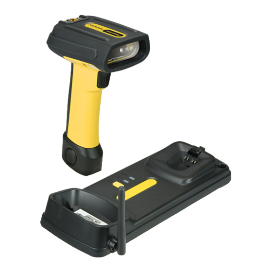
Chapter 2 Getting Started About the Reader Advancements in the LED technology used in this reader significantly improve the illu- mination of the target field of view, resulting in higher scan efficiency. Whether used in Single Trigger or Continuous Mode, the ergonomic design of the reader will help to pro- mote comfortable handling during extended periods of use. -
Page 16: Setting Up The Reader And Base Station
Getting Started Setting Up the Reader and Base Station Follow the steps provided in this section to connect and get your reader up and commu- nicating with its host: Install the Battery in the Reader Connect the Base Station Select the Interface Type Configure Interface Settings (only if not using factory settings for that interface) Configure Other Features... -
Page 17: Linking The Reader To A Base Station
Linking the Reader to a Base Station Host Connection — The interface type was specified at the time your reader was or- dered, however you should verify before connection that the reader’s cable type is com- patible with your host equipment. Most connections plug directly into the host device as shown in . -
Page 18: Optional: Linking The Reader To A Pc
Link to a PC 3. On the PC, scan for network devices. 4. Select the “Datalogic PBT7100 Reader.” Make sure “Secure Connection” is disabled. 5. Select “connect” on the PC to link the reader to the PC. PowerScan® PBT7100 Cordless... -
Page 19: Paging Feature
Paging Feature Paging Feature To help locate a missing reader, press the Base Station Link Button momentarily (less than one second). This will cause the reader to beep five times at its loudest volume set- ting. Programming The reader is typically factory-configured with a set of default features. After scanning the interface barcode from the section, you can select other options and cus- Interfaces... -
Page 20: Configure Other Features
Getting Started • USB-OEM Interface, starting on page 87 • IBM 46XX Interface, starting on page 89 Configure Other Features If your installation requires different programming than the standard factory default set- tings, the following sections of this manual allow configuration of non-interface-specific settings you might require: —... -
Page 21: Chapter 3. Interfaces
Chapter 3 Interfaces Interface Selection Each reader model will support one of the following sets of host interfaces: General Purpose Models (5 volt supply) RS-232 RS-232 OPOS Keyboard Wedge Retail Point of Sale Models (4 to 14 volt supply) RS-232 RS-232 OPOS IBM 46XX Configuring the Interface... - Page 22 89 IBM-46xx Port 9B reader interface Select IBM-P9B USB-OEM FEATURES Set USB-OEM Interface USB-OEM Features (can be used for OPOS/UPOS/JavaPOS) starting on page 87 Select USB-OEM Download the correct USB Com driver from www.datalogic.com PowerScan® PBT7100 Cordless...
- Page 23 Configuring the Interface KEYBOARD FEATURES AT, PS/2 25-286, 30-286, 50, 50Z, 60, 70, 80, 90 & 95 w/Standard Key Encoding Select KBD-AT Keyboard Wedge for IBM AT PS2 with standard key encoding but without external keyboard Select KBD-AT-NK AT, PS/2 25-286, 30-286, 50, 50Z, 60, 70, 80, 90 & 95 Set KEYBOARD w/Alternate Key WEDGE...
- Page 24 Interfaces KEYBOARD — cont. FEATURES Keyboard Wedge for IBM Terminals 31xx, 32xx, 34xx, 37xx make only keyboard Select KBD-IBM-M Keyboard Wedge for IBM Terminals 31xx, 32xx, 34xx, 37xx make break keyboard Select KBD-IBM-MB Keyboard Wedge for DIGITAL Terminals VT2xx, VT3xx, VT4xx Set KEYBOARD WEDGE Select KBD-DIG-VT...
-
Page 25: Global Interface Features
Global Interface Features Global Interface Features The following interface features are configurable by all interface types. To set features specific to your interface, turn to that section of this manual: • RS-232 ONLY Interface on page 47 • Keyboard Interface on page 73 •... -
Page 26: Usb Suspend Mode
Interfaces USB Suspend Mode This setting enables/disables the ability of USB interfaces to enter suspend mode. ENTER/EXIT PROGRAMMING MODE DEFAULT USB Suspend Mode = Disable USB Suspend Mode = Enable PowerScan® PBT7100 Cordless... -
Page 27: Chapter 4. General Features
Chapter 4 General Features Double Read Timeout To prevent a double read of the same label, the Double Read Timeout sets the minimum time allowed between reads of labels of the same symbology and data. If the unit reads a label and sees the same label again within the Double Read Timeout, the second read of the label will be ignored. - Page 28 General Features Double Read Timeout — continued ENTER/EXIT PROGRAMMING MODE Double Read Timeout = 0.5 Second Double Read Timeout = 0.6 Second Double Read Timeout = 0.7 Second Double Read Timeout = 0.8 Second Double Read Timeout = 0.9 Second Double Read Timeout = 1 Second PowerScan®...
-
Page 29: Label Gone Timeout
Label Gone Timeout Label Gone Timeout This feature sets the time after the last label segment is seen before the reader prepares for a new label. The timeout can be set within a range of 10 milliseconds to 2,550 millisec- onds (2.55 seconds) in 10ms increments. - Page 30 General Features Label Gone Timeout — cont. ENTER/EXIT PROGRAMMING MODE Select Label Gone Timeout Setting Make a mistake? Scan the CANCEL barcode to abort and not save the entry string. You can then start again at the beginning. CANCEL 016 = Timeout of 160 ms DEFAULT PowerScan®...
-
Page 31: Sleep Mode Timeout
Sleep Mode Timeout Sleep Mode Timeout Specifies the timeout value for the reader to enter low power Sleep Mode. ENTER/EXIT PROGRAMMING MODE DEFAULT Sleep Mode Timeout = Disable Sleep Mode Timeout = 500ms Sleep Mode Timeout = 1 Second Sleep Mode Timeout = 2 Seconds Sleep Mode Timeout = 3 Seconds Sleep Mode Timeout = 4 Seconds Product Reference Guide... - Page 32 General Features Sleep Mode Timeout — continued ENTER/EXIT PROGRAMMING MODE Sleep Mode Timeout = 5 Seconds Sleep Mode Timeout = 6 Seconds Sleep Mode Timeout = 7 Seconds Sleep Mode Timeout = 8 Seconds Sleep Mode Timeout = 9 Seconds Sleep Mode Timeout = 9.9 Seconds (9,900ms max.) PowerScan®...
-
Page 33: Led And Beeper Indicators
LED and Beeper Indicators LED and Beeper Indicators Power On Alert Disables or enables the indication (from the Beeper) that the reader is receiving power. ENTER/EXIT PROGRAMMING MODE Power On Alert = Disable (No Audible Indication) DEFAULT Power On Alert = Four Beeps Product Reference Guide... -
Page 34: Good Read: When To Indicate
General Features Good Read: When to Indicate This feature specifies when the reader will provide indication (beep and/or flash its green LED) upon successfully reading a barcode. Choices are: • Good Read = Indicate after decode • Good Read = Indicate after transmit •... -
Page 35: Good Read Beep Type
LED and Beeper Indicators Good Read Beep Type Specifies whether the good read beep has a mono or bitonal beep sound. ENTER/EXIT PROGRAMMING MODE DEFAULT Good Read Beep Type = Mono Good Read Beep Type = Bitonal Product Reference Guide... -
Page 36: Good Read Beep Frequency
General Features Good Read Beep Frequency Adjusts the good read beep to sound at a selectable low, medium or high frequency, se- lectable from the list below. (Controls the beeper’s pitch/tone.) ENTER/EXIT PROGRAMMING MODE Good Read Beep Frequency = Low Good Read Beep Frequency = Medium DEFAULT Good Read Beep Frequency = High... - Page 37 LED and Beeper Indicators Good Read Beep Length — continued ENTER/EXIT PROGRAMMING MODE DEFAULT Good Read Beep Length = 80 msec Good Read Beep Length = 100 msec Good Read Beep Length = 120 msec Good Read Beep Length = 140 msec Good Read Beep Length = 160 msec Good Read Beep Length = 180 msec Good Read Beep Length = 200 msec...
-
Page 38: Good Read Beep Volume
General Features Good Read Beep Volume Selects the beeper volume (loudness) upon a good read beep. There are three selectable volume levels. ENTER/EXIT PROGRAMMING MODE Good Read Beep Volume = Beeper Off Good Read Beep Volume = Low Good Read Beep Volume = Medium DEFAULT Good Read Beep Volume = High PowerScan®... -
Page 39: Good Read Led Duration
LED and Beeper Indicators Good Read LED Duration This feature specifies the amount of time that the Good Read LED remains on following a good read. The good read LED on time can be set within a range of 10 milliseconds to 2,550 milliseconds (0.001 to 2.55 seconds) in 10ms increments. - Page 40 General Features Good Read LED Duration — cont. ENTER/EXIT PROGRAMMING MODE Select Good Read LED Duration Setting Make a mistake? Scan the CANCEL barcode to abort and not save the entry string. You can then start again at the beginning. CANCEL 020 = Good Read LED stays on for DEFAULT...
-
Page 41: Scanning Features
Scanning Features Scanning Features Scan Mode Selects the scan operating mode for the reader. Selections are: Trigger Single — When the trigger is pulled, scanning is activated until one of the fol- lowing occurs: Scanning Active Time has elapsed - a label has been read - the trigger is released This mode is associated with typical handheld reader operation: when the trigger is pulled, scanning starts and the product scans until the trigger is released, or a label is read,... - Page 42 General Features Scan Mode — continued ENTER/EXIT PROGRAMMING MODE DEFAULT Scan Mode = Trigger Single Scan Mode = Trigger Hold Multiple Scan Mode = Trigger Pulse Multiple Scan Mode = Flashing Scan Mode = Always On Scan Mode = Stand Mode Scan Mode = Trigger Object Sense PowerScan®...
-
Page 43: Stand Mode Triggered Timeout
Scanning Features Stand Mode Triggered Timeout This feature specifies the time to remain in mode after the trigger is pulled Trigger Single while in Stand Mode. Stand This timeout is only used when the Scan Mode is configured as Mode. NOTE ENTER/EXIT PROGRAMMING MODE DEFAULT... - Page 44 General Features Stand Mode Triggered Timeout — continued ENTER/EXIT PROGRAMMING MODE Stand Mode Triggered Timeout = 6 Seconds Stand Mode Triggered Timeout = 8 Seconds Stand Mode Triggered Timeout = Switch back to Trigger Single on trigger pull PowerScan® PBT7100 Cordless...
-
Page 45: Scanning Active Time
Scanning Features Scanning Active Time This setting specifies the amount of time that the reader stays in scan ON state once the state is entered. The range for this setting is from 1 to 255 seconds in 1-second incre- ments. Follow these instructions to set this feature: 1. - Page 46 General Features Scanning Active Time — cont. ENTER/EXIT PROGRAMMING MODE Select Scanning Active Time Setting Make a mistake? Scan the CANCEL barcode to abort and not save the entry string. You can then start again at the beginning. CANCEL DEFAULT 005 = Scanning is active for 5 Seconds PowerScan®...
-
Page 47: Flash On Time
Flash On Time Flash On Time This feature specifies the ON time for the indicator LED while in Flash Mode. The se- lectable range is 100 to 9,900 milliseconds (0.1 to 9.9 seconds), in 100 millisecond in- crements. Follow these instructions to set this feature. 1. - Page 48 General Features Flash On Time — cont. ENTER/EXIT PROGRAMMING MODE Select Flash ON Time Setting Make a mistake? Scan the CANCEL barcode to abort and not save the entry string. You can then start again at the beginning. CANCEL 10 = Flash is ON for 1 Second DEFAULT PowerScan®...
-
Page 49: Flash Off Time
Flash Off Time Flash Off Time This feature specifies the OFF time for the indicator LED while in Flash Mode. The se- lectable range is 100 to 9,900 milliseconds (0.1 to 9.9 seconds), in 100 millisecond in- crements. Follow these instructions to set this feature. 1. - Page 50 General Features Flash Off Time — cont. ENTER/EXIT PROGRAMMING MODE Select Flash OFF Time Setting Make a mistake? Scan the CANCEL barcode to abort and not save the entry string. You can then start again at the beginning. CANCEL 06 = Flash is OFF for 600ms DEFAULT PowerScan®...
-
Page 51: Stand Mode Sensitivity
Stand Mode Sensitivity Stand Mode Sensitivity Sets the sensitivity level for stand mode wakeup. Choices are low, medium and high. ENTER/EXIT PROGRAMMING MODE Stand Mode Sensitivity = Low DEFAULT Stand Mode Sensitivity = Medium Stand Mode Sensitivity = High Product Reference Guide... -
Page 52: Laser Pointer Control
General Features Laser Pointer Control The Laser Pointer is a value-added option which might not have been included when your reader was ordered. NOTE Specifies the amount of time that the laser pointer is turned on preliminary to scanning. When the trigger is pressed in Trigger Single Mode, the laser pointer will be activated for the time period configured by this feature. -
Page 53: Laser Pointer Period
Laser Pointer Period Laser Pointer Period This option specifies the period of the laser pointer blink during scanning. The laser pointer will be activated for the time specified by Control. then start blinking Laser Pointer OFF then ON at 50% duty cycle for the duration set by Laser Pointer Period. - Page 54 General Features Laser Pointer Period — cont. Laser Pointer Period = 2.5 Seconds (2,500 ms) Laser Pointer Period = 3 Seconds (3,000 ms) Laser Pointer Period = 3.5 Seconds (3,500 ms) Laser Pointer Period = 4 Seconds (4,000 ms) Laser Pointer Period = 4.5 Seconds (4,500 ms) Laser Pointer Period = 5 Seconds (5,000 ms) PowerScan®...
-
Page 55: Green Spot Duration
Green Spot Duration Green Spot Duration Specifies the duration of the good read pointer beam after a good read. ENTER/EXIT PROGRAMMING MODE Green Spot Duration = Disable (Green Spot is Off) DEFAULT Green Spot Duration = Short (300 msec) Green Spot Duration = Medium (500 msec) Green Spot Duration = Long (800 msec) Product Reference Guide... - Page 56 General Features NOTES PowerScan® PBT7100 Cordless...
-
Page 57: Chapter 5. Rs-232 Only Interface
Chapter 5 RS-232 ONLY Interface Introduction Use the programming barcodes in this chapter if modifications to the standard RS-232 interface settings are necessary to meet your system’s requirements. Additional settings which apply to both the RS-232 and USB interfaces are available in Chapter 6, RS-232/ USB-Com Interfaces RS-232 Standard Factory Settings... - Page 58 RS-232 ONLY Interface Baud Rate — continued ENTER/EXIT PROGRAMMING MODE DEFAULT Baud Rate = 9600 Baud Rate = 19,200 Baud Rate = 38,400 Baud Rate = 57,600 Baud Rate = 115,200 PowerScan® PBT7100 Cordless...
-
Page 59: Data Bits
Data Bits Data Bits This parameter allows the reader to interface with devices requiring a 7-bit or 8-bit ASCII protocol for sending and receiving data. ENTER/EXIT PROGRAMMING MODE 7 Data Bits DEFAULT 8 Data Bits Product Reference Guide... -
Page 60: Stop Bits
RS-232 ONLY Interface Stop Bits The stop bit(s) at the end of each transmitted character marks the end of transmission of one character and prepares the receiving device for the next character in the serial data stream. The number of stop bits selected (one or two) depends on the number the receiv- ing terminal is programmed to accommodate. -
Page 61: Parity
Parity Parity This feature specifies parity required for sending and receiving data. A parity check bit is the most significant bit of each ASCII coded character. Select the parity type according to host device requirements. • Select None when no parity bit is required. •... -
Page 62: Handshaking Control
RS-232 ONLY Interface Handshaking Control The data interface consists of an RS-232 port designed to operate either with or without the hardware handshaking lines, Request to Send (RTS), and Clear to Send (CTS). Hand- shaking Control includes the following options: •... -
Page 63: Chapter 6. Rs-232/Usb-Com Interfaces
Chapter 6 RS-232/USB-Com Interfaces Introduction The programming barcodes in this chapter allow modifications to the standard RS-232 and USB-Com interfaces. Standard Factory Settings Reference for a listing of standard factory settings. Appendix B, Standard Defaults Product Reference Guide... -
Page 64: Intercharacter Delay
RS-232/USB-Com Interfaces Intercharacter Delay This parameter specifies the intercharacter delay between the end of one character and the beginning of the next. The delay can be set within a range of zero (0) to 990 milliseconds in 10ms increments. A setting of zero specifies no delay. To set the delay: 1. - Page 65 Intercharacter Delay Intercharacter Delay — cont. ENTER/EXIT PROGRAMMING MODE Intercharacter Delay = No Delay Select Intercharacter Delay Setting Make a mistake? Scan the CANCEL barcode to abort and not save the entry string. You can then start again at the beginning. CANCEL 00 = No Intercharacter Delay DEFAULT...
-
Page 66: Beep On Ascii Bel
RS-232/USB-Com Interfaces Beep On ASCII BEL When this parameter is enabled, the reader issues a beep when a <BEL> character is de- tected on the RS-232 serial line. <BEL> is issued to gain a user's attention to an illegal entry or other important event. ENTER/EXIT PROGRAMMING MODE DEFAULT Beep On ASCII BEL = Disable... -
Page 67: Ack Nak Options
ACK NAK Options ACK NAK Options This enables/disables the ability of the reader to support the RS-232 ACK/NAK proto- col. When configured, the reader and/or host sends an “ACK” when it receives data properly, and sends “NAK” when the data is in error. Options are: •... -
Page 68: Ack Character
RS-232/USB-Com Interfaces ACK Character This setting specifies an ASCII character or hex value to be used as the ACK character. ASCII characters or any hex value from 0 to 0xFF can be selected. Setting to previously defined characters such as XON, XOFF, or host commands conflicts with normal operation of these characters. - Page 69 ACK NAK Options ACK Character — cont. ENTER/EXIT PROGRAMMING MODE Select ACK Character Setting 0x06 ‘ACK’ Character DEFAULT Product Reference Guide...
-
Page 70: Nak Character
RS-232/USB-Com Interfaces NAK Character This setting specifies an ASCII character or hex value to be used as the NAK character. ASCII characters or any hex value from 0 to 0xFF can be selected. Setting to previously defined characters such as XON, XOFF, or host commands conflicts with normal operation of these characters. - Page 71 ACK NAK Options NAK Character — cont. ENTER/EXIT PROGRAMMING MODE Select NAK Character Setting 0x15 ‘NAK’ Character DEFAULT Product Reference Guide...
-
Page 72: Ack Nak Timeout Value
RS-232/USB-Com Interfaces ACK NAK Timeout Value This option specifies the amount of time the reader waits for an ACK character from the host following label transmission. The selectable timeout range is 200 milliseconds to 15,000ms (15 seconds) in 200ms increments. A selection of 0 disables the timeout. To set this value: 1. - Page 73 ACK NAK Options ACK NAK Timeout Value — cont. ENTER/EXIT PROGRAMMING MODE Select ACK NAK Timeout Value Setting Make a mistake? Scan the CANCEL barcode to abort and not save the entry string. You can then start again at the beginning. CANCEL 01 ACK NAK Timeout value is 200ms DEFAULT...
-
Page 74: Ack Nak Retry Count
RS-232/USB-Com Interfaces ACK NAK Retry Count This feature specifies the number of times the reader retries a label transmission due to a retry condition. The selectable range is from 1 to 254 retries. A selection of 0 disables the count, and a selection of 255 specifies unlimited retries. To set this feature: 1. - Page 75 ACK NAK Options ACK NAK Retry Count — cont. ENTER/EXIT PROGRAMMING MODE Select ACK NAK Retry Count Setting Make a mistake? Scan the CANCEL barcode to abort and not save the entry string. You can then start again at the beginning. CANCEL 003 = 3 Retries DEFAULT...
-
Page 76: Ack Nak Error Handling
RS-232/USB-Com Interfaces ACK NAK Error Handling This feature specifies the method the reader uses to handle receive errors detected while waiting for an ACK character from the host. Options are: • Ignore errors detected • Process error as valid ACK character •... -
Page 77: Indicate Transmission Failure
Indicate Transmission Failure Indicate Transmission Failure This option enables/disables the reader’s ability to sound an error beep to indicate a transmission failure while in ACK/NAK mode. ENTER/EXIT PROGRAMMING MODE Indicate Transmission Failure = Disable Indication DEFAULT Indicate Transmission Failure = Enable Indication Product Reference Guide... -
Page 78: Disable Character
RS-232/USB-Com Interfaces Disable Character Specifies the value of the RS-232 host command used to disable the reader. ASCII characters or any hex value from 0 to 0xFF can be selected. Setting to previously defined characters such as XON, XOFF, or host commands conflicts with normal operation of these characters. - Page 79 Disable Character Disable Character — cont. ENTER/EXIT PROGRAMMING MODE Select Disable Character Setting 0x44 = Disable Character is ‘D’ DEFAULT Product Reference Guide...
-
Page 80: Enable Character
RS-232/USB-Com Interfaces Enable Character Specifies the value of the RS-232 host command used to enable the reader. ASCII characters or any hex value from 0 to 0xFF can be selected. Setting to previously defined characters such as XON, XOFF, or host commands conflicts with normal operation of these characters. - Page 81 Enable Character Enable Character — cont. ENTER/EXIT PROGRAMMING MODE Select Enable Character Setting 0x45 = Enable Character is ‘E’ DEFAULT Product Reference Guide...
- Page 82 RS-232/USB-Com Interfaces NOTES PowerScan® PBT7100 Cordless...
-
Page 83: Chapter 7. Keyboard Interface
Chapter 7 Keyboard Interface Introduction Use the programming barcodes in this chapter to select options for USB Keyboard and Wedge Interfaces. Standard Factory Settings Reference for a listing of standard factory settings. Appendix B, Standard Defaults Scancode Tables Information about control character emulation which applies to keyboard interfaces is listed in Appendix F, Scancode Tables Product Reference Guide... -
Page 84: Country Mode
Keyboard Interface Country Mode This feature specifies the country/language supported by the keyboard. Only the following interfaces support ALL Country Modes. • USB Keyboard (without alternate key encoding) • AT, PS/2 25-286, 30-286, 50, 50Z, 60, 70, 80, 90 & 95 w/Std Key Encoding •... - Page 85 Country Mode Country Mode — continued ENTER/EXIT PROGRAMMING MODE Supports only the interfaces listed in theCountry Mode feature description. Country Mode = Denmark Country Mode = France Country Mode = Germany Supports only the interfaces listed in theCountry Mode feature description.
- Page 86 Keyboard Interface Country Mode — continued ENTER/EXIT PROGRAMMING MODE Supports only the interfaces listed in theCountry Mode feature description. Country Mode = Poland Supports only the interfaces listed in theCountry Mode feature description. Country Mode = Portugal Supports only the interfaces listed in theCountry Mode feature description.
-
Page 87: Caps Lock State
Caps Lock State Caps Lock State This option specifies the format in which the reader sends character data. This applies to keyboard wedge interfaces. This does not apply when an alternate key encoding keyboard is selected. ENTER/EXIT PROGRAMMING MODE DEFAULT Caps Lock State = Caps Lock OFF Caps Lock State = Caps Lock ON Caps Lock State = AUTO Caps Lock Enable... -
Page 88: Send Control Characters
Keyboard Interface Send Control Characters This feature Specifies how the reader transmits ASCII control characters to the host. Ref- erence for more information about control characters. Appendix F, Scancode Tables Options are as follows: Control Character 00 — Characters from 00 to 0x1F are sent as control character Ctrl+Keys, special keys are located from 0x80 to 0xA1. -
Page 89: Wedge Quiet Interval
Wedge Quiet Interval Wedge Quiet Interval This option specifies the amount of time to look for keyboard activity before the read- er breaks the keyboard connection in order to transmit data to host. The selectable range for this feature is from 0 to 990ms in 10ms increments. This feature applies ONLY to the Keyboard Wedge interface. - Page 90 Keyboard Interface Wedge Quiet Interval — cont. ENTER/EXIT PROGRAMMING MODE Select Wedge Quiet Interval Setting Make a mistake? Scan the CANCEL barcode to abort and not save the entry string. You can then start again at the beginning. CANCEL 10 = Quiet Interval of 100 ms DEFAULT PowerScan®...
-
Page 91: Intercharacter Delay
Intercharacter Delay Intercharacter Delay This parameter specifies the intercharacter delay between the end of one character and the beginning of the next. The delay can be set within a range of zero (0) to 990 milliseconds in 10ms increments. A setting of zero specifies no delay. This feature applies ONLY to the Keyboard Wedge interface. - Page 92 Keyboard Interface Intercharacter Delay — cont. ENTER/EXIT PROGRAMMING MODE Intercharacter Delay = No Delay Select Intercharacter Delay Setting Make a mistake? Scan the CANCEL barcode to abort and not save the entry string. You can then start again at the beginning. CANCEL 00 = No Intercharacter Delay DEFAULT...
-
Page 93: Intercode Delay
Intercode Delay Intercode Delay Specifies the delay between labels transmitted to the host for this interface. The selectable range for this feature is from 0 to 99 seconds. Follow these instructions to set this feature: 1. Determine the desired setting. 2. - Page 94 Keyboard Interface Intercode Delay — cont. ENTER/EXIT PROGRAMMING MODE Set Intercode Delay Make a mistake? Scan the CANCEL barcode to abort and not save the entry string. You can then start again at the beginning. CANCEL 00 = No Wedge Intercode Delay DEFAULT PowerScan®...
-
Page 95: Usb Keyboard Speed
USB Keyboard Speed USB Keyboard Speed This option specifies the USB poll rate for a USB keyboard. This feature applies ONLY to the USB Keyboard interface. NOTE ENTER/EXIT PROGRAMMING MODE DEFAULT USB Keyboard Speed = 1ms USB Keyboard Speed = 2ms USB Keyboard Speed = 3ms USB Keyboard Speed = 4ms USB Keyboard Speed = 5ms... - Page 96 Keyboard Interface USB Keyboard Speed — continued ENTER/EXIT PROGRAMMING MODE USB Keyboard Speed = 6ms USB Keyboard Speed = 7ms USB Keyboard Speed = 8ms USB Keyboard Speed = 9ms USB Keyboard Speed = 10ms PowerScan® PBT7100 Cordless...
-
Page 97: Chapter 8. Usb-Oem Interface
Chapter 8 USB-OEM Interface Introduction Feature settings for USB interfaces differ depending upon which host type the reader will be connected with. Use the feature settings in this chapter and Chapter 9, IBM 46XX to specifically configure for the USB-OEM interface. Other USB interfaces are Interface included in the approprite chapter for their host type. -
Page 98: Usb-Oem Device Usage
USB-OEM Interface USB-OEM Device Usage The USB-OEM protocol allows for the reader to be identified as one of two different types of barcode scanners. Depending on what other scanners you may already have con- nected to a USB-OEM POS, you may need to change this setting to enable all devices to communicate. -
Page 99: Chapter 9. Ibm 46Xx Interface
Chapter 9 IBM 46XX Interface Introduction Use the barcodes in this section to configure programmable features for available IBM 46XX interfaces. IBM Standard Factory Settings Reference for a listing of standard factory settings. Appendix B, Standard Defaults Product Reference Guide... -
Page 100: 46Xx Number Of Host Resets
IBM 46XX Interface 46xx Number of Host Resets Specifies how many consecutive resets are processed before the reader starts a five-second period to allow the user to enter Programming Mode and configure the reader. The con- figurable range for this feature is 1 to 15 resets. ENTER/EXIT PROGRAMMING MODE 46xx Number of Host Resets = 1 46xx Number of Host Resets = 2... - Page 101 46xx Number of Host Resets 46xx Number of Host Resets — cont. ENTER/EXIT PROGRAMMING MODE 46xx Number of Host Resets = 7 46xx Number of Host Resets = 8 46xx Number of Host Resets = 9 46xx Number of Host Resets = 10 46xx Number of Host Resets = 11 46xx Number of Host Resets = 12 Product Reference Guide...
- Page 102 IBM 46XX Interface 46xx Number of Host Resets — cont. ENTER/EXIT PROGRAMMING MODE 46xx Number of Host Resets = 13 46xx Number of Host Resets = 14 46xx Number of Host Resets = 15 PowerScan® PBT7100 Cordless...
-
Page 103: Transmit Labels In Code 39 Format
Transmit Labels in Code 39 Format Transmit Labels in Code 39 Format This feature enable/disables translation to Code 39 before transmitting label data to an IBM-46XX or a USB-OEM host. Only the symbology identifier is modified for the translation. The data is not converted to Code 39 or verified to be valid for Code 39. Options are: IBM Standard Format —... - Page 104 IBM 46XX Interface NOTES PowerScan® PBT7100 Cordless...
-
Page 105: Chapter 10. Data Editing
Chapter 10 Data Editing Data Editing Overview It is not recommended to use these features with IBM interfaces. CAUTION When a barcode is scanned, additional information can be sent to the host computer along with the barcode data. This combination of barcode data and supplementary user- defined data is called a “message string.”... -
Page 106: Please Keep In Mind
Data Editing Please Keep In Mind... • Modifying a message string is not a mandatory requirement. Data editing is sophisticated feature allowing highly customizable output for advanced users. Factory default settings for data editing is typically set to NONE. • A prefix or suffix may be applied (reference the Symbologies chapter for these settings) - Page 107 Global Prefix/Suffix 6. Scan the ENTER/EXIT barcode once again to exit Programming Mode. 7. The resulting message string would appear as follows: Scanned barcode data:12345 Resulting message string output: $12345 This option sets up to 20 characters each from the set of ASCII characters or any hex val- ue from 00 to FF.
-
Page 108: Global Aim Id
Data Editing Global AIM ID This feature enables/disables addition of AIM IDs for all symbology types. NOTE AIM label identifiers (as opposed to custom characters you select yourself as with label identifiers) can be included with scanned barcode data. AIM label identifiers consist of three characters as follows: •... - Page 109 Global AIM ID Global AIM ID — continued ENTER/EXIT PROGRAMMING MODE DEFAULT Global AIM ID = Disable Global AIM ID = Enable Product Reference Guide...
-
Page 110: Gs1-128 Aim Id
Data Editing GS1-128 AIM ID If Global AIM ID is disabled, the AIM ID for GS1-128 can be enabled/disabled inde- pendently. The AIM ID for GS1-128 is a ]C1, ]C2 or ]C3. AIM IDs for other symbologies can be enabled/disabled independently as well. Contact Customer Support for assistance. -
Page 111: Label Id
Label ID Label ID A Label ID is a customizable code of up to three ASCII characters (each can be one of hex 0x01-0xFF), used to identify a barcode (symbology) type. It can be appended previ- ous to or following the transmitted barcode data depending upon how this option is en- abled. - Page 112 6A0000 6A0000 CODE93 & 260000 550000 GS1 DATABAR OMNIDIRECTIONAL 523400 750000 GS1 DATABAR EXPANDED 525800 740000 GS1 DATABAR LIMITED 524C00 760000 DATALOGIC 2OF5 730000 730000 GS1-128 000000 6B0000 EAN13 460000 420000 EAN13 P2 460000 4C0000 EAN13 P5 460000 4D0000 EAN13 P8...
-
Page 113: Label Id: Set Individually Per Symbology
Label ID Label ID: Set Individually Per Symbology To configure a Label ID individually for a single symbology: 1. Scan the ENTER/EXIT barcode. 2. Select Label ID position as either BEFORE (Enable as Prefix) or AFTER (Enable as suf- fix) by scanning the appropriate barcode in the section Label ID Control on page 105. - Page 114 Data Editing Label ID — continued Table 18. Label ID Examples STEP ACTION EXAMPLES Scan the ENTER/EXIT barcode (Scanner enters Programming Mode) Determine placement of the Label ID characters BEFORE or AFTER with regard to scanned data using Enable as Prefix Enable as Suffix Enable as Prefix Enable as Suffix...
-
Page 115: Label Id Control
Label ID Label ID — continued Label ID Control This option controls whether a Label ID is disabled, or sent as a prefix or suffix for a given symbology type. ENTER/EXIT PROGRAMMING MODE DEFAULT Label ID Transmission = Disable Label ID Transmission = Enable as Prefix Label ID Transmission = Enable as Suffix Make a mistake? Scan the CANCEL barcode to abort and not save the entry string. -
Page 116: Label Id Symbology Selection
Data Editing Label ID — continued Label ID Symbology Selection This option selects the symbology for which a Label ID is to be configured. See Label ID for full instructions. on page 101 ENTER/EXIT PROGRAMMING MODE Set UPC-A Label ID Character(s) Set UPC-A/P2 Label ID Character(s) Set UPC-A/P5 Label ID Character(s) Set UPC-A/GS1-128 Label ID Character(s) - Page 117 Label ID Label ID — continued Label ID Symbology Selection — continued This option selects the symbology for which a Label ID is to be configured. See Label ID for full instructions. on page 101 ENTER/EXIT PROGRAMMING MODE Set UPC-E/P5 Label ID Character(s) Set UPC-E/GS1-128 Label ID Character(s) Set EAN 13 Label ID Character(s) Set EAN 13/P2 Label ID Character(s)
- Page 118 Data Editing Label ID — continued Label ID Symbology Selection — continued This option selects the symbology for which a Label ID is to be configured. See Label ID for full instructions. on page 101 ENTER/EXIT PROGRAMMING MODE Set EAN 8 Label ID Character(s) Set EAN 8/P2 Label ID Character(s) Set EAN 8/P5 Label ID Character(s) Set EAN 8/GS1-128 Label ID Character(s)
- Page 119 Label ID Label ID — continued Label ID Symbology Selection — continued This option selects the symbology for which a Label ID is to be configured. See Label ID for full instructions. on page 101 ENTER/EXIT PROGRAMMING MODE Set GTIN/P5 Label ID Character(s) Set GTIN/GS1-128 Label ID Character(s) Set GS1 DataBar Omnidirectional Label ID Character(s) Set GS1 DataBar Expanded Label ID Character(s)
- Page 120 Data Editing Label ID — continued Label ID Symbology Selection — continued This option selects the symbology for which a Label ID is to be configured. See Label ID for full instructions. on page 101 ENTER/EXIT PROGRAMMING MODE Set Code 32 Label ID Character(s) Set Code 128 Label ID Character(s) Set ISBT 128 Label ID Character(s) Set GS1-128 Label ID Character(s)
- Page 121 Label ID Label ID — continued Label ID Symbology Selection — continued This option selects the symbology for which a Label ID is to be configured. See Label ID for full instructions. on page 101 ENTER/EXIT PROGRAMMING MODE Set Standard 2 of 5 Label ID Character(s) Set Code 4 Label ID Character(s) Set Code 5 Label ID Character(s) Set Follett 2 of 5 Label ID Character(s)
-
Page 122: Case Conversion
Data Editing Case Conversion This feature allows conversion of the case of all alphabetic characters to upper or lower case. Case conversion affects ONLY scanned barcode data, and does not affect Label ID, Prefix, Suffix, or other appended data. NOTE ENTER/EXIT PROGRAMMING MODE DEFAULT Case Conversion = Disable (no case conversion) -
Page 123: Character Conversion
Character Conversion Character Conversion Character conversion is an eight byte configuration item. The eight bytes are 4 character pairs represented in hexadecimal ASCII values. The first character in the pair is the char- acter that will be converted. The second character in the pair is the character to convert to. - Page 124 Data Editing Character Conversion — continued ENTER/EXIT PROGRAMMING MODE Configure Character Conversion 0xFFFFFFFFFFFFFFFF DEFAULT (No character conversion) PowerScan® PBT7100 Cordless...
-
Page 125: Chapter 11. Symbologies
UPC-A • GS1-128 • UPC-E • Interleaved 2 of 5 (I 2 of 5) • EAN 13 (JAN 13) • Datalogic 2 of 5 • EAN 8 (JAN 8) • Codabar • GS1 DataBar Omnidirectional • Code 11 • GS1 DataBar Expanded •... -
Page 126: Coupon Control
Symbologies Coupon Control This feature is used to control the method of processing coupon labels. Options are: • Disable coupon decoding • Enable UPC-A coupon decoding • Enable GS1 DataBar coupon decoding To set this feature: 1. Scan the SWITCH bar code. 2. -
Page 127: Upc-A
UPC-A UPC-A The following options apply to the UPC-A symbology. UPC-A Enable/Disable When disabled, the reader will not read UPC-A barcodes. ENTER/EXIT PROGRAMMING MODE UPC-A = Disable DEFAULT UPC-A = Enable UPC-A Check Character Transmission Enable this option to transmit the check character along with UPC-A barcode data. ENTER/EXIT PROGRAMMING MODE UPC-A Check Character Transmission = Don’t Send DEFAULT... -
Page 128: Expand Upc-A To Ean-13
Symbologies UPC-A — cont. Expand UPC-A to EAN-13 Expands UPC-A data to the EAN-13 data format. Selecting this feature also changes the symbology ID to match those required for EAN-13. ENTER/EXIT PROGRAMMING MODE DEFAULT UPC-A to EAN-13 = Don’t Expand UPC-A to EAN-13 = Expand UPC-A Number System Character Transmission This feature enables/disables transmission of the UPC-A number system character. -
Page 129: In-Store Minimum Reads
UPC-A UPC-A — cont. In-Store Minimum Reads This feature specifies the minimum number of consecutive times an in-store label must be decoded before it is accepted as good read. In-store labels are defined as UPC-A labels with a number-system character of 2 or 4 as well as EAN 8 and EAN 13 labels with a Flag1 character of 2 or an EAN 13 label starting with the three characters '980'. -
Page 130: Upc-E
Symbologies UPC-E The following options apply to the UPC-E symbology. UPC-E Enable/Disable When disabled, the reader will not read UPC-E barcodes. ENTER/EXIT PROGRAMMING MODE UPC-E = Disable DEFAULT UPC-E = Enable UPC-E Check Character Transmission Enable this option to transmit the check character along with UPC-E barcode data. ENTER/EXIT PROGRAMMING MODE UPC-E Check Character Transmission = Don’t Send DEFAULT... -
Page 131: Expand Upc-E To Ean-13
UPC-E UPC-E — cont. Expand UPC-E to EAN-13 Expands UPC-E data to the EAN-13 data format. Selecting this feature also changes the symbology ID to match those required for EAN-13. ENTER/EXIT PROGRAMMING MODE DEFAULT UPC-E to EAN-13 = Don’t Expand UPC-E to EAN-13 = Expand Expand UPC-E to UPC-A Expands UPC-E data to the UPC-A data format. -
Page 132: Upc-E Number System Character Transmission
Symbologies UPC-E — cont. UPC-E Number System Character Transmission This feature enables/disables transmission of the UPC-E system number character. ENTER/EXIT PROGRAMMING MODE UPC-E Number System Character = Do not transmit DEFAULT UPC-E Number System Character = Transmit PowerScan® PBT7100 Cordless... -
Page 133: Upc-E Minimum Reads
UPC-E UPC-E — cont. UPC-E Minimum Reads This feature specifies the minimum number of consecutive times a UPC-E label must be decoded before it is accepted as good read.. ENTER/EXIT PROGRAMMING MODE UPC-E Minimum Reads = 1 DEFAULT UPC-E Minimum Reads = 2 UPC-E Minimum Reads = 3 UPC-E Minimum Reads = 4 Product Reference Guide... -
Page 134: Gtin Formatting
Symbologies GTIN Formatting This feature enables/disables the ability to convert UPC-E, UPC-A, EAN 8, and EAN 13 labels into the GTIN 14-character format. If add-on information is present on the base label prior to the conver- sion taking place, the addon information will be appended to the con- verted GTIN label. -
Page 135: Ean 13
EAN 13 EAN 13 The following options apply to the EAN 13 (Jan 13) symbology. EAN 13 Enable/Disable When disabled, the reader will not read EAN 13/JAN 13 barcodes. ENTER/EXIT PROGRAMMING MODE EAN 13 = Disable DEFAULT EAN 13 = Enable EAN 13 Check Character Transmission Enable this option to transmit the check character along with EAN 13 barcode data. -
Page 136: Ean-13 Flag 1 Character
Symbologies EAN 13 — cont. EAN-13 Flag 1 Character Enables/disables transmission of an EAN/JAN13 Flag1 character. The Flag 1 character is the first character of the label. ENTER/EXIT PROGRAMMING MODE EAN-13 Flag 1 Char= Don’t transmit DEFAULT EAN-13 Flag 1 Char= Transmit PowerScan®... -
Page 137: Ean-13 Isbn Conversion
EAN 13 EAN-13 ISBN Conversion This option enables/disables conversion of EAN 13/JAN 13 Bookland labels starting with 978 to ISBN labels. ENTER/EXIT PROGRAMMING MODE DEFAULT EAN-13 ISBN Conversion = Disable EAN-13 ISBN Conversion = Convert to ISBN Product Reference Guide... -
Page 138: Ean 13 Minimum Reads
Symbologies EAN 13 — cont. EAN 13 Minimum Reads This feature specifies the minimum number of consecutive times an EAN 13 label must be decoded before it is accepted as good read.. ENTER/EXIT PROGRAMMING MODE DEFAULT EAN 13 Minimum Reads = 1 EAN 13 Minimum Reads = 2 EAN 13 Minimum Reads = 3 EAN 13 Minimum Reads = 4... -
Page 139: Ean 8
EAN 8 EAN 8 The following options apply to the EAN 8 (Jan 8) symbology. EAN 8 Enable/Disable When disabled, the reader will not read EAN 8/JAN 8 barcodes. ENTER/EXIT PROGRAMMING MODE EAN 8 = Disable DEFAULT EAN 8 = Enable EAN 8 Check Character Transmission Enable this option to transmit the check character along with EAN 8 barcode data. -
Page 140: Expand Ean 8 To Ean 13
Symbologies EAN 8 — cont. Expand EAN 8 to EAN 13 Enable this option to expand EAN 8/JAN 8 labels to EAN 13/JAN 13. ENTER/EXIT PROGRAMMING MODE DEFAULT Expand EAN 8 to EAN 13 = Disable Expand EAN 8 to EAN 13 = Enable PowerScan®... -
Page 141: Ean 8 Minimum Reads
EAN 8 EAN 8 — cont. EAN 8 Minimum Reads This feature specifies the minimum number of consecutive times an EAN 8 (Jan 8) label must be decoded before it is accepted as good read.. ENTER/EXIT PROGRAMMING MODE DEFAULT EAN 8 Minimum Reads = 1 EAN 8 Minimum Reads = 2 EAN 8 Minimum Reads = 3 EAN 8 Minimum Reads = 4... -
Page 142: Upc/Ean Global Settings
Symbologies UPC/EAN Global Settings This section provides configuration settings for UPC-A, UPC-E, EAN 13 and EAN 8 symbologies, and affects all of these unless otherwise marked for each feature description. UPC/EAN Decoding Level Decoding Levels are used to configure a barcode symbology decoder to be very aggressive to very conservative depending on a particular customer’s needs. - Page 143 UPC/EAN Global Settings UPC/EAN Global Settings — cont. UPC/EAN Decoding Level — cont. ENTER/EXIT PROGRAMMING MODE UPC/EAN Decoding Level = 1 DEFAULT UPC/EAN Decoding Level = 2 UPC/EAN Decoding Level = 3 UPC/EAN Decoding Level = 4 UPC/EAN Decoding Level = 5 Product Reference Guide...
-
Page 144: Upc/Ean Correlation
Symbologies UPC/EAN Global Settings — cont. UPC/EAN Correlation When correlation is enabled, the barcode reader will combine label data from multiple scans when decoding. Enabling correlation will help the scanner read labels that have some spots and/or voids. It may also help read labels that have damaged areas. Enabling correlation will also increase the chances that a label will be read incorrectly. -
Page 145: Upc/Ean Price Weight Check
UPC/EAN Global Settings UPC/EAN Global Settings — cont. UPC/EAN Price Weight Check This feature enables/disables calculation and verification of price/weight check digits. Options are • Disabled • Enable 4-digit price-weight check-digit calculation • Enable 5-digit price-weight check-digit calculation • Enable European 4-digit price-weight check-digit calculation •... -
Page 146: Upc-A Minimum Reads
Symbologies UPC/EAN Global Settings — cont. UPC-A Minimum Reads This feature specifies the minimum number of consecutive times a UPC-A label must be decoded before it is accepted as good read.. ENTER/EXIT PROGRAMMING MODE DEFAULT UPC-A Minimum Reads = 1 UPC-A Minimum Reads = 2 UPC-A Minimum Reads = 3 UPC-A Minimum Reads = 4... -
Page 147: Add-Ons
Add-Ons Add-Ons The following features apply to optional add-ons. Contact Customer Support for advanced programming of optional and conditional add-ons. NOTE Optional Add-ons The reader can be enabled to optionally read the following add-ons (supplementals): • • • GS1-128 If a UPC/EAN base label and a an add-on are both decoded, the reader will transmit the base label and add-on. - Page 148 Symbologies Add-Ons — cont. Optional Add-ons — cont. ENTER/EXIT PROGRAMMING MODE Optional Add-Ons = Enable P5 DEFAULT Optional Add-Ons = Disable GS1-128 Optional Add-Ons = Enable GS1-128 PowerScan® PBT7100 Cordless...
-
Page 149: Optional Add-On Timer
Add-Ons Add-Ons — cont. Optional Add-On Timer This option sets the time the reader will look for an add-on when an add-on fragment has been seen and optional add-ons are enabled. (Also see Optional GS1-128 Add-On Timer on page 142 ENTER/EXIT PROGRAMMING MODE Optional Add-on Timer = 10ms Optional Add-on Timer = 20ms... - Page 150 Symbologies Add-Ons — cont. Optional Add-On Timer — cont. ENTER/EXIT PROGRAMMING MODE Optional Add-on Timer = 60ms DEFAULT Optional Add-on Timer = 70ms Optional Add-on Timer = 100ms Optional Add-on Timer = 120ms Optional Add-on Timer = 140ms Optional Add-on Timer = 160ms PowerScan®...
- Page 151 Add-Ons Add-Ons — cont. Optional Add-On Timer — cont. ENTER/EXIT PROGRAMMING MODE Optional Add-on Timer = 180ms Optional Add-on Timer = 200ms Optional Add-on Timer = 220ms Optional Add-on Timer = 240ms Optional Add-on Timer = 260ms Optional Add-on Timer = 280ms Optional Add-on Timer = 300ms Product Reference Guide...
-
Page 152: Optional Gs1-128 Add-On Timer
Symbologies Add-Ons — cont. Optional GS1-128 Add-On Timer This option sets the timer expiration value to read the added part after reading the linear EAN/UPC part. For UPC/EAN add-ons other than those of that type, see Optional Add-On Timer on page 139 ENTER/EXIT PROGRAMMING MODE DEFAULT Optional GS1-128 Add-On Timer = Disable... - Page 153 Add-Ons Add-Ons — cont. Optional GS1-128 Add-On Timer — cont. ENTER/EXIT PROGRAMMING MODE Optional GS1-128 Add-On Timer = 60ms Optional GS1-128 Add-On Timer = 70ms Optional GS1-128 Add-On Timer = 100ms Optional GS1-128 Add-On Timer = 120ms Optional GS1-128 Add-On Timer = 140ms Optional GS1-128 Add-On Timer = 160ms Product Reference Guide...
- Page 154 Symbologies Add-Ons — cont. Optional GS1-128 Add-On Timer — cont. ENTER/EXIT PROGRAMMING MODE Optional GS1-128 Add-On Timer = 180ms Optional GS1-128 Add-On Timer = 200ms Optional GS1-128 Add-On Timer = 220ms Optional GS1-128 Add-On Timer = 240ms Optional GS1-128 Add-On Timer = 260ms Optional GS1-128 Add-On Timer = 280ms Optional GS1-128 Add-On Timer = 300ms PowerScan®...
-
Page 155: P2 Add-Ons Minimum Reads
Add-Ons Add-Ons — cont. P2 Add-Ons Minimum Reads This feature specifies the minimum number of times a P2 add-on must be read before it is marked as valid and then combined with a base label. ENTER/EXIT PROGRAMMING MODE P2 Add-Ons Minimum Reads = 1 DEFAULT P2 Add-Ons Minimum Reads = 2 P2 Add-Ons Minimum Reads = 3... -
Page 156: P5 Add-Ons Minimum Reads
Symbologies Add-Ons — cont. P5 Add-Ons Minimum Reads This feature specifies the minimum number of times a P5 add-on must be read before it is marked as valid and then combined with a base label. ENTER/EXIT PROGRAMMING MODE DEFAULT P5 Add-Ons Minimum Reads = 1 P5 Add-Ons Minimum Reads = 2 P5 Add-Ons Minimum Reads = 3 P5 Add-Ons Minimum Reads = 4... -
Page 157: Gs1-128 Add-Ons Minimum Reads
Add-Ons Add-Ons — cont. GS1-128 Add-Ons Minimum Reads This feature specifies the minimum number of times an GS1-128 add-on must be read before it is marked as valid and then combined with a base label. ENTER/EXIT PROGRAMMING MODE DEFAULT GS1-128 Add-Ons Minimum Reads = 1 GS1-128 Add-Ons Minimum Reads = 2 GS1-128 Add-Ons Minimum Reads = 3 GS1-128 Add-Ons Minimum Reads = 4... -
Page 158: Gs1 Databar Omnidirectional
Symbologies GS1 DataBar Omnidirectional The following options apply to the GS1 DataBar Omnidirectional (formerly RSS-14) symbology. GS1 DataBar Omnidirectional Enable/Disable When disabled, the reader will not read GS1 DataBar Omnidirectional barcodes. ENTER/EXIT PROGRAMMING MODE DEFAULT GS1 DataBar Omnidirectional = Disable GS1 DataBar Omnidirectional = Enable GS1 DataBar Omnidirectional GS1-128 Emulation When enabled, GS1 DataBar Omnidirectional barcodes will be translated to the GS1-... -
Page 159: Gs1 Databar Omnidirectional Minimum Reads
GS1 DataBar Omnidirectional GS1 DataBar Omnidirectional — cont. GS1 DataBar Omnidirectional Minimum Reads This feature specifies the minimum number of consecutive times a GS1 DataBar Omni- directional label must be decoded before it is accepted as good read. ENTER/EXIT PROGRAMMING MODE DEFAULT GS1 DataBar Omnidirectional Minimum Reads = 1 GS1 DataBar Omnidirectional Minimum Reads = 2... -
Page 160: Gs1 Databar Expanded
Symbologies GS1 DataBar Expanded The following options apply to the GS1 DataBar Expanded (formerly RSS Expanded) symbology. GS1 DataBar Expanded Enable/Disable When disabled, the reader will not read GS1 DataBar Expanded barcodes. ENTER/EXIT PROGRAMMING MODE DEFAULT GS1 DataBar Expanded = Disable GS1 DataBar Expanded = Enable GS1 DataBar Expanded GS1-128 Emulation When enabled, GS1 DataBar Expanded barcodes will be translated to the GS1-128 label... -
Page 161: Gs1 Databar Expanded Minimum Reads
GS1 DataBar Expanded GS1 DataBar Expanded — cont. GS1 DataBar Expanded Minimum Reads This feature specifies the minimum number of consecutive times a GS1 DataBar Ex- panded label must be decoded before it is accepted as good read. ENTER/EXIT PROGRAMMING MODE DEFAULT GS1 DataBar Expanded Minimum Reads = 1 GS1 DataBar Expanded Minimum Reads = 2... -
Page 162: Gs1 Databar Expanded Length Control
Symbologies GS1 DataBar Expanded — cont. GS1 DataBar Expanded Length Control This feature specifies either variable length decoding or fixed length decoding for the GS1 DataBar Expanded symbology. Variable Length — For variable-length decoding, a minimum length may be set. Fixed Length —... -
Page 163: Gs1 Databar Expanded Set Length 1
GS1 DataBar Expanded GS1 DataBar Expanded — cont. GS1 DataBar Expanded Set Length 1 This feature specifies one of the barcode lengths for GS1 DataBar Expanded Length . Length 1 is the minimum label length if in Mode, or the first Control Variable Length fixed length if in... - Page 164 Symbologies GS1 DataBar Expanded — cont. GS1 DataBar Expanded Set Length 1 — cont. ENTER/EXIT PROGRAMMING MODE Select GS1 DataBar Expanded Set Length 1 Setting Make a mistake? Scan the CANCEL barcode to abort and not save the entry string. You can then start again at the beginning. CANCEL 01 = Length 1 is 1 Character DEFAULT...
-
Page 165: Gs1 Databar Expanded Set Length 2
GS1 DataBar Expanded GS1 DataBar Expanded — cont. GS1 DataBar Expanded Set Length 2 This feature specifies one of the barcode lengths for GS1 DataBar Expanded Length . Length 2 is the maximum label length if in Mode, or the sec- Control Variable Length ond fixed length if in... - Page 166 Symbologies GS1 DataBar Expanded — cont. GS1 DataBar Expanded Set Length 2 — cont. ENTER/EXIT PROGRAMMING MODE Select GS1 DataBar Expanded Set Length 2 Setting Make a mistake? Scan the CANCEL barcode to abort and not save the entry string. You can then start again at the beginning. CANCEL 74 = Length 2 is 74 Characters DEFAULT...
-
Page 167: Gs1 Databar Limited
GS1 DataBar Limited GS1 DataBar Limited The following options apply to the GS1 DataBar Limited (formerly RSS Limited) sym- bology. GS1 DataBar Limited Enable/Disable When disabled, the reader will not read GS1 DataBar Limited barcodes. ENTER/EXIT PROGRAMMING MODE DEFAULT GS1 DataBar Limited = Disable GS1 DataBar Limited = Enable GS1 DataBar Limited GS1-128 Emulation When enabled, GS1 DataBar Limited barcodes will be translated to the GS1-128 label... -
Page 168: Gs1 Databar Limited Minimum Reads
Symbologies GS1 DataBar Limited — cont. GS1 DataBar Limited Minimum Reads This feature specifies the minimum number of consecutive times a GS1 DataBar Limited label must be decoded before it is accepted as good read. ENTER/EXIT PROGRAMMING MODE DEFAULT GS1 DataBar Limited Minimum Reads = 1 GS1 DataBar Limited Minimum Reads = 2 GS1 DataBar Limited Minimum Reads = 3 GS1 DataBar Limited Minimum Reads = 4... -
Page 169: Code 39
Code 39 Code 39 The following options apply to the Code 39 symbology. Code 39 Enable/Disable When disabled, the reader will not read Code 39 barcodes. ENTER/EXIT PROGRAMMING MODE Code 39 = Disable DEFAULT Code 39 = Enable Product Reference Guide... -
Page 170: Code 39 Check Character Calculation
Symbologies Code 39 — cont. Code 39 Check Character Calculation Enable this option to enables/disables calculation and verification of an optional Code 39 check character. When disabled, any check character in the label is treated as a data character ENTER/EXIT PROGRAMMING MODE Code 39 Check Character Calculation = Don’t Calculate DEFAULT Code 39 Check Character Calculation = Calculate Std Check... -
Page 171: Code 39 Check Character Transmission
Code 39 Code 39 — cont. Code 39 Check Character Transmission Enable this option to transmit the check character along with Code 39 barcode data. ENTER/EXIT PROGRAMMING MODE Code 39 Check Character Transmission = Don’t Send DEFAULT Code 39 Check Character Transmission = Send Code 39 Start/Stop Character Transmission Enable this option to enable/disable transmission of Code 39 start and stop characters. -
Page 172: Code 39 Full Ascii
Symbologies Code 39 — cont. Code 39 Full ASCII In Code 39 decoding, this enables/disables the translation of Code 39 characters to Code 39 full-ASCII characters. ENTER/EXIT PROGRAMMING MODE DEFAULT Code 39 Full ASCII = Disable Code 39 Full ASCII = Enable PowerScan®... -
Page 173: Code 39 Quiet Zones
Code 39 Code 39 — cont. Code 39 Quiet Zones This feature specifies the number of quiet zones for Code 39 labels. Quiet zones are blank areas at the ends of a barcode and are typically 10 times the width of the narrowest bar or space in the label. -
Page 174: Code 39 Minimum Reads
Symbologies Code 39 — cont. Code 39 Minimum Reads This feature specifies the minimum number of consecutive times a Code 39 label must be decoded before it is accepted as good read.. ENTER/EXIT PROGRAMMING MODE DEFAULT Code 39 Minimum Reads = 1 Code 39 Minimum Reads = 2 Code 39 Minimum Reads = 3 Code 39 Minimum Reads = 4... -
Page 175: Code 39 Decoding Level
Code 39 Code 39 — cont. Code 39 Decoding Level Decoding Levels are used to configure a barcode symbology decoder to be very aggressive to very conservative depending on a particular customer’s needs. • Choosing Level 1 results in a very conservative decoder at the expense of not being able to read poorly printed or damaged labels. - Page 176 Symbologies Code 39 — cont. Code 39 Decoding Level — cont. ENTER/EXIT PROGRAMMING MODE Code 39 Decoding Level = 1 Code 39 Decoding Level = 2 DEFAULT Code 39 Decoding Level = 3 Code 39 Decoding Level = 4 Code 39 Decoding Level = 5 PowerScan®...
-
Page 177: Code 39 Length Control
Code 39 Code 39 — cont. Code 39 Length Control This feature specifies either variable length decoding or fixed length decoding for the Code 39 symbology. Variable Length — For variable length decoding, a minimum and maximum length may be set. Fixed Length —... -
Page 178: Code 39 Set Length 1
Symbologies Code 39 — cont. Code 39 Set Length 1 This feature specifies one of the barcode lengths for . Length 1 Code 39 Length Control is the minimum label length if in Mode, or the first fixed length if in Variable Length Mode. - Page 179 Code 39 Code 39 — cont. Code 39 Set Length 1 — cont. ENTER/EXIT PROGRAMMING MODE Select Code 39 Set Length 1 Setting Make a mistake? Scan the CANCEL barcode to abort and not save the entry string. You can then start again at the beginning. CANCEL 02 = Length 1 is 2 Characters DEFAULT...
-
Page 180: Code 39 Set Length 2
Symbologies Code 39 — cont. Code 39 Set Length 2 This feature specifies one of the barcode lengths for . Length 2 Code 39 Length Control is the maximum label length if in Mode, or the second fixed length if Variable Length Mode. - Page 181 Code 39 Code 39 — cont. Code 39 Set Length 2 — cont. ENTER/EXIT PROGRAMMING MODE Select Code 39Length 2 Setting Make a mistake? Scan the CANCEL barcode to abort and not save the entry string. You can then start again at the beginning. CANCEL 50 = Length 2 is 50 Characters DEFAULT...
-
Page 182: Code 39 Interdigit Ratio
Symbologies Code 39 — cont. Code 39 Interdigit Ratio This feature specifies the ratio between an intercharacter space and module for Code 39 labels. ENTER/EXIT PROGRAMMING MODE Code 39 Interdigit Ratio = Disable Code 39 Interdigit Ratio = 1 Code 39 Interdigit Ratio = 2 Code 39 Interdigit Ratio = 3 DEFAULT Code 39 Interdigit Ratio = 4... - Page 183 Code 39 Code 39 — cont. Code 39 Interdigit Ratio — cont. ENTER/EXIT PROGRAMMING MODE Code 39 Interdigit Ratio = 6 Code 39 Interdigit Ratio = 7 Code 39 Interdigit Ratio = 8 Code 39 Interdigit Ratio = 9 Code 39 Interdigit Ratio = 10 Product Reference Guide...
-
Page 184: Code 39 Character Correlation
Symbologies Code 39 — cont. Code 39 Character Correlation When correlation is enabled, the barcode reader will combine label data from multiple scans when decoding. Enabling correlation will help the scanner read labels that have some spots and/or voids. It may also help read labels that have damaged areas. Enabling correlation will also increase the chances that a label will be read incorrectly. -
Page 185: Code 39 Stitching
Code 39 Code 39 Stitching This option enables/disables stitching for Code 39 labels. When parts of a Code 39 bar- code are presented to the reader with this feature enabled, the barcode parts will be as- sembled by the reader’s software, and the data will be decoded if all barcode proofing requirements are met. -
Page 186: Code 32
Symbologies Code 32 The following options apply to the Code 32 (Italian Pharamaceutical Code) symbology. Code 32 Enable/Disable When disabled, the reader will not read Code 32 barcodes. ENTER/EXIT PROGRAMMING MODE DEFAULT Code 32 = Disable Code 32 = Enable Code 32 Feature Setting Exceptions The following features are set for Code 32 by using these Code 39 settings: Code 39 Quiet Zones on page 163... -
Page 187: Code 32 Check Character Transmission
Code 32 Code 32 — cont. Code 32 Check Character Transmission Enable this option to transmit the check character along with Code 32 barcode data. ENTER/EXIT PROGRAMMING MODE DEFAULT Code 32 Check Character Transmission = Don’t Send Code 32 Check Character Transmission = Send Code 32 Start/Stop Character Transmission This option enables/disable transmission of Code 32 start and stop characters. -
Page 188: Code 128
Symbologies Code 128 The following options apply to the Code 128 symbology. Code 128 Enable/Disable When disabled, the reader will not read Code 128 barcodes. ENTER/EXIT PROGRAMMING MODE Code 128 = Disable DEFAULT Code 128 = Enable Expand Code 128 to Code 39 This feature enables/disables expansion of Code 128 labels to Code 39 labels. -
Page 189: Code 128 Check Character Transmission
Code 128 Code 128 — cont. Code 128 Check Character Transmission Enable this option to transmit the check character along with Code 128 barcode data. ENTER/EXIT PROGRAMMING MODE DEFAULT Code 128 Check Character Transmission = Don’t Send Code 128 Check Character Transmission = Send Code 128 Function Character Transmission Enables/disables transmission of Code128 function characters 1, 2, 3, and 4. -
Page 190: Code 128 Sub-Code Change Transmission
Symbologies Code 128 — cont. Code 128 Sub-Code Change Transmission Enables/disables the transmission of “Sub-Code exchange” characters (NOT transmitted by standard decoding). ENTER/EXIT PROGRAMMING MODE DEFAULT Code 128 Sub-Code Change Transmission = Disable Code 128 Sub-Code Change Transmission = Enable PowerScan®... -
Page 191: Code 128 Quiet Zones
Code 128 Code 128 — cont. Code 128 Quiet Zones This feature specifies the number of quiet zones for Code 128 labels. Quiet zones are blank areas at the ends of a barcode and are typically 10 times the width of the narrowest bar or space in the label. -
Page 192: Code 128 Minimum Reads
Symbologies Code 128 — cont. Code 128 Minimum Reads This feature specifies the minimum number of consecutive times a Code 128 label must be decoded before it is accepted as good read.. ENTER/EXIT PROGRAMMING MODE DEFAULT Code 128 Minimum Reads = 1 Code 128 Minimum Reads = 2 Code 128 Minimum Reads = 3 Code 128 Minimum Reads = 4... -
Page 193: Code 128 Decoding Level
Code 128 Code 128 — cont. Code 128 Decoding Level Decoding Levels are used to configure a barcode symbology decoder to be very aggressive to very conservative depending on a particular customer’s needs. • Choosing Level 1 results in a very conservative decoder at the expense of not being able to read poorly printed or damaged labels. - Page 194 Symbologies Code 128 — cont. Code 128 Decoding Level — cont. ENTER/EXIT PROGRAMMING MODE Code 128 Decoding Level = 1 Code 128 Decoding Level = 2 DEFAULT Code 128 Decoding Level = 3 Code 128 Decoding Level = 4 Code 128 Decoding Level = 5 PowerScan®...
-
Page 195: Code 128 Length Control
Code 128 Code 128 — cont. Code 128 Length Control This feature specifies either variable length decoding or fixed length decoding for the Code 128 symbology. Variable Length — For variable length decoding, a minimum and maximum length may be set. Fixed Length —... -
Page 196: Code 128 Set Length 1
Symbologies Code 128 — cont. Code 128 Set Length 1 This feature specifies one of the barcode lengths for . Length Code 128 Length Control 1 is the minimum label length if in Mode, or the first fixed length if in Variable Length Mode. - Page 197 Code 128 Code 128 — cont. Code 128 Set Length 1 — cont. ENTER/EXIT PROGRAMMING MODE Select Code 128 Set Length 1 Setting Make a mistake? Scan the CANCEL barcode to abort and not save the entry string. You can then start again at the beginning. CANCEL 01 = Length 1 is 1 Character DEFAULT...
-
Page 198: Code 128 Set Length 2
Symbologies Code 128 — cont. Code 128 Set Length 2 This feature specifies one of the barcode lengths for . Length Code 128 Length Control 2 is the maximum label length if in Mode, or the second fixed length if Variable Length Mode. - Page 199 Code 128 Code 128 — cont. Code 128 Set Length 2 — cont. ENTER/EXIT PROGRAMMING MODE Select Code 128 Length 2 Setting Make a mistake? Scan the CANCEL barcode to abort and not save the entry string. You can then start again at the beginning. CANCEL 80 = Length 2 is 80 Characters DEFAULT...
-
Page 200: Code 128 Character Correlation
Symbologies Code 128 — cont. Code 128 Character Correlation When correlation is enabled, the barcode reader will combine label data from multiple scans when decoding. Enabling correlation will help the scanner read labels that have some spots and/or voids. It may also help read labels that have damaged areas. Enabling correlation will also increase the chances that a label will be read incorrectly. -
Page 201: Code 128 Stitching
Code 128 Code 128 — cont. Code 128 Stitching This option enables/disables stitching for Code 128 labels. When parts of a Code 128 barcode are presented to the reader with this feature enabled, the barcode parts will be assembled by the reader’s software, and the data will be decoded if all barcode proofing requirements are met. -
Page 202: Gs1-128
Symbologies GS1-128 The following options apply to the GS1-128 symbology. (Also known as USS-128, GTIN-128, UCC-128, EAN 128.) GS1-128 Enable This option enables/disables the ability of the reader to translate GS1-128 labels to the GS1-128 data format. Options are: • Transmit GS1-128 labels in Code 128 data format. -
Page 203: Interleaved 2 Of 5 (I 2 Of 5)
Interleaved 2 of 5 (I 2 of 5) Interleaved 2 of 5 (I 2 of 5) The following options apply to the I 2 of 5 symbology. I 2 of 5 Enable/Disable When disabled, the reader will not read I 2 of 5 barcodes. ENTER/EXIT PROGRAMMING MODE DEFAULT I 2 of 5 = Disable... -
Page 204: I 2 Of 5 Check Character Calculation
Symbologies Interleaved 2 of 5 (I 2 of 5) — cont. I 2 of 5 Check Character Calculation This option enables/disables calculation and verification of an optional I 2 of 5 check character. ENTER/EXIT PROGRAMMING MODE DEFAULT I 2 of 5 Check Character Calculation = Disable I 2 of 5 Check Character Calculation = Check Standard (Modulo 10) I 2 of 5 Check Character Calculation = Check German Parcel... -
Page 205: I 2 Of 5 Check Character Transmission
Interleaved 2 of 5 (I 2 of 5) Interleaved 2 of 5 (I 2 of 5) — cont. I 2 of 5 Check Character Transmission Enable this option to transmit the check character along with I 2 of 5 barcode data. ENTER/EXIT PROGRAMMING MODE I 2 of 5 Check Character Transmission = Don’t Send DEFAULT... -
Page 206: I 2 Of 5 Minimum Reads = 2
Symbologies Interleaved 2 of 5 (I 2 of 5) — cont. I 2 of 5 Minimum Reads This feature specifies the minimum number of consecutive times an I 2 of 5 label must be decoded before it is accepted as good read.. ENTER/EXIT PROGRAMMING MODE DEFAULT I 2 of 5 Minimum Reads = 1... -
Page 207: I 2 Of 5 Decoding Level
Interleaved 2 of 5 (I 2 of 5) Interleaved 2 of 5 (I 2 of 5) — cont. I 2 of 5 Decoding Level This configuration item applies to Interleaved 2 of 5, Datalogic 2 of 5 and Standard 2 of 5. NOTE Decoding Levels are used to configure a barcode symbology decoder to be very aggressive to very conservative depending on a particular customer’s needs. - Page 208 Symbologies Interleaved 2 of 5 (I 2 of 5) — cont. I 2 of 5 Decoding Level — cont. ENTER/EXIT PROGRAMMING MODE 2 of 5 Decoding Level = 1 2 of 5 Decoding Level = 2 DEFAULT 2 of 5 Decoding Level = 3 2 of 5 Decoding Level = 4 2 of 5 Decoding Level = 5 PowerScan®...
-
Page 209: I 2 Of 5 Length Control
Interleaved 2 of 5 (I 2 of 5) Interleaved 2 of 5 (I 2 of 5) — cont. I 2 of 5 Length Control This feature specifies either variable length decoding or fixed length decoding for the I 2 of 5 symbology. Variable Length —... -
Page 210: I 2 Of 5 Set Length 1
Symbologies Interleaved 2 of 5 (I 2 of 5) — cont. I 2 of 5 Set Length 1 This feature specifies one of the barcode lengths for . Length 1 is I 2 of 5 Length Control the minimum label length if in Mode, or the first fixed length if in Variable Length Mode. - Page 211 Interleaved 2 of 5 (I 2 of 5) Interleaved 2 of 5 (I 2 of 5) — cont. Datalogic 2 of 5 Set Length 1 — cont. ENTER/EXIT PROGRAMMING MODE Select I 2 of 5 Length 1 Setting Make a mistake? Scan the CANCEL barcode to abort and not save the entry string.
-
Page 212: I 2 Of 5 Set Length 2
Symbologies Interleaved 2 of 5 (I 2 of 5) — cont. I 2 of 5 Set Length 2 This feature specifies one of the barcode lengths for . Length 2 is I 2 of 5 Length Control the maximum label length if in Mode, or the second fixed length if in Variable Length Mode. - Page 213 Interleaved 2 of 5 (I 2 of 5) Interleaved 2 of 5 (I 2 of 5) — cont. I 2 of 5 Set Length 2 — cont. ENTER/EXIT PROGRAMMING MODE Select I 2 of 5 Length 2 Setting Make a mistake? Scan the CANCEL barcode to abort and not save the entry string.
-
Page 214: I 2 Of 5 Character Correlation
Symbologies Interleaved 2 of 5 (I 2 of 5) — cont. I 2 of 5 Character Correlation When correlation is enabled, the barcode reader will combine label data from multiple scans when decoding. Enabling correlation will help the scanner read labels that have some spots and/or voids. -
Page 215: I 2 Of 5 Stitching
Interleaved 2 of 5 (I 2 of 5) Interleaved 2 of 5 (I 2 of 5) — cont. I 2 of 5 Stitching This option enables/disables stitching for I 2 of 5 labels. When parts of a I 2 of 5 barcode are presented to the reader with this feature enabled, the barcode parts will be assembled by the reader’s software, and the data will be decoded if all barcode proofing require- ments are met. -
Page 216: Datalogic 2 Of 5
Datalogic 2 of 5 The following options apply to the Datalogic 2 of 5 symbology. Datalogic 2 of 5 Enable/Disable When disabled, the reader will not read Datalogic 2 of 5 barcodes. ENTER/EXIT PROGRAMMING MODE DEFAULT Datalogic 2 of 5 = Disable Datalogic 2 of 5 = Enable PowerScan®... -
Page 217: Datalogic 2 Of 5 Check Character Calculation
Datalogic 2 of 5 Datalogic 2 of 5 — cont. Datalogic 2 of 5 Check Character Calculation This option enables/disables calculation and verification of an optional Datalogic 2 of 5 check character. ENTER/EXIT PROGRAMMING MODE DEFAULT Datalogic 2 of 5 Check Character Calculation = Disable... -
Page 218: Datalogic 2 Of 5 Minimum Reads
Datalogic 2 of 5 — cont. Datalogic 2 of 5 Minimum Reads This feature specifies the minimum number of consecutive times an Datalogic 2 of 5 la- bel must be decoded before it is accepted as good read. ENTER/EXIT PROGRAMMING MODE... -
Page 219: Datalogic 2 Of 5 Length Control
Fixed Length — For fixed length decoding, two different lengths may be set. ENTER/EXIT PROGRAMMING MODE DEFAULT Datalogic 2 of 5 Length Control = Variable Length Datalogic 2 of 5 Length Control = Fixed Length Product Reference Guide... -
Page 220: Datalogic 2 Of 5 Set Length 1
6. Scan the ENTER/EXIT PROGRAMMING MODE barcode to exit Programming Mode. This completes the procedure. See for some examples of how to set this feature. Table 27 Table 27. Datalogic 2 of 5 Length 1 Setting Examples STEP ACTION EXAMPLES Desired Setting... - Page 221 Datalogic 2 of 5 Datalogic 2 of 5 — cont. Datalogic 2 of 5 Set Length 1 — cont. ENTER/EXIT PROGRAMMING MODE Select Datalogic 2 of 5 Length 1 Setting Make a mistake? Scan the CANCEL barcode to abort and not save the entry string.
-
Page 222: Datalogic 2 Of 5 Set Length 2
20, etc. 3. Scan the ENTER/EXIT PROGRAMMING MODE barcode to enter Programming Mode. 4. Scan the barcode: SELECT Datalogic 2 of 5 LENGTH 2 SETTING. 5. Scan the appropriate two digits from the keypad in Appendix E, Keypad, that represent the length setting which was determined in the steps above. - Page 223 Datalogic 2 of 5 Datalogic 2 of 5 — cont. Datalogic 2 of 5 Set Length 2 — cont. ENTER/EXIT PROGRAMMING MODE Select Datalogic 2 of 5 Length 2 Setting Make a mistake? Scan the CANCEL barcode to abort and not save the entry string.
-
Page 224: Datalogic 2 Of 5 Interdigit Maximum Ratio
This feature specifies the maximum ratio between intercharacter space and module for Datalogic 2 of 5. ENTER/EXIT PROGRAMMING MODE Datalogic 2 of 5 Interdigit Maximum Ratio = Disable Datalogic 2 of 5 Interdigit Maximum Ratio = 1 Datalogic 2 of 5 Interdigit Maximum Ratio = 2... - Page 225 Datalogic 2 of 5 Datalogic 2 of 5 Interdigit Maximum Ratio — cont. Datalogic 2 of 5 Interdigit Maximum Ratio = 6 Datalogic 2 of 5 Interdigit Maximum Ratio = 7 Datalogic 2 of 5 Interdigit Maximum Ratio = 8...
-
Page 226: Datalogic 2 Of 5 Character Correlation
Symbologies Datalogic 2 of 5 — cont. Datalogic 2 of 5 Character Correlation When correlation is enabled, the barcode reader will combine label data from multiple scans when decoding. Enabling correlation will help the scanner read labels that have some spots and/or voids. It may also help read labels that have damaged areas. Enabling correlation will also increase the chances that a label will be read incorrectly. -
Page 227: Datalogic 2 Of 5 Stitching
Datalogic 2 of 5 — cont. Datalogic 2 of 5 Stitching This option enables/disables stitching for Datalogic 2 of 5 labels. When parts of a Data- logic 2 of 5 barcode are presented to the reader with this feature enabled, the barcode parts will be assembled by the reader’s software, and the data will be decoded if all bar-... -
Page 228: Codabar
Symbologies Codabar The following options apply to the Codabar symbology. Codabar Enable/Disable When disabled, the reader will not read Codabar barcodes. ENTER/EXIT PROGRAMMING MODE DEFAULT Codabar = Disable Codabar = Enable PowerScan® PBT7100 Cordless... -
Page 229: Codabar Check Character Calculation
Codabar Codabar — cont. Codabar Check Character Calculation Enable this option to enables/disables calculation and verification of an optional Codabar check character. When disabled, any check character in the label is treated as a data character ENTER/EXIT PROGRAMMING MODE DEFAULT Codabar Check Character Calculation = Don’t Calculate Codabar Check Character Calculation = Enable AIM standard check char. -
Page 230: Codabar Check Character Transmission
Symbologies Codabar — cont. Codabar Check Character Transmission Enable this option to transmit the check character along with Codabar barcode data. ENTER/EXIT PROGRAMMING MODE Codabar Check Character Transmission = Don’t Send DEFAULT Codabar Check Character Transmission = Send Codabar Start/Stop Character Transmission Enable this option to enable/disable transmission of Codabar start and stop characters. -
Page 231: Codabar Start/Stop Character Set
Codabar Codabar — cont. Codabar Start/Stop Character Set This option specifies the format of transmitted Codabar start/stop characters. ENTER/EXIT PROGRAMMING MODE Codabar Check Character Set = ABCD/TN*E Codabar Check Character Set = ABCD/ABCD Codabar Check Character Set = abcd/tn*e DEFAULT Codabar Check Character Set = abcd/abcd Product Reference Guide... -
Page 232: Codabar Start/Stop Character Match
Symbologies Codabar — cont. Codabar Start/Stop Character Match When enabled, this option requires that start and stop characters match. ENTER/EXIT PROGRAMMING MODE DEFAULT Codabar Start/Stop Character Match = Don’t Require Match Codabar Start/Stop Character Match = Require Match PowerScan® PBT7100 Cordless... -
Page 233: Codabar Quiet Zones
Codabar Codabar — cont. Codabar Quiet Zones This feature specifies the number of quiet zones for Codabar labels. Quiet zones are blank areas at the ends of a barcode and are typically 10 times the width of the narrowest bar or space in the label. -
Page 234: Codabar Minimum Reads
Symbologies Codabar — cont. Codabar Minimum Reads This feature specifies the minimum number of consecutive times a Codabar label must be decoded before it is accepted as good read.. ENTER/EXIT PROGRAMMING MODE DEFAULT Codabar Minimum Reads = 1 Codabar Minimum Reads = 2 Codabar Minimum Reads = 3 Codabar Minimum Reads = 4 PowerScan®... -
Page 235: Codabar Decoding Level
Codabar Codabar — cont. Codabar Decoding Level Decoding Levels are used to configure a barcode symbology decoder to be very aggressive to very conservative depending on a particular customer’s needs. • Choosing Level 1 results in a very conservative decoder at the expense of not being able to read poorly printed or damaged labels. - Page 236 Symbologies Codabar — cont. Codabar Decoding Level — cont. ENTER/EXIT PROGRAMMING MODE Codabar Decoding Level = 1 Codabar Decoding Level = 2 DEFAULT Codabar Decoding Level = 3 Codabar Decoding Level = 4 Codabar Decoding Level = 5 PowerScan® PBT7100 Cordless...
-
Page 237: Codabar Length Control
Codabar Codabar — cont. Codabar Length Control This feature specifies either variable length decoding or fixed length decoding for the Codabar symbology. Variable Length — For variable length decoding, a minimum and maximum length may be set. Fixed Length — For fixed length decoding, two different lengths may be set. -
Page 238: Codabar Set Length 1
Symbologies Codabar — cont. Codabar Set Length 1 This feature specifies one of the barcode lengths for . Length 1 Codabar Length Control is the minimum label length if in Mode, or the first fixed length if in Variable Length Mode. - Page 239 Codabar Codabar — cont. Codabar Set Length 1 — cont. ENTER/EXIT PROGRAMMING MODE Select Codabar Length 1 Setting Make a mistake? Scan the CANCEL barcode to abort and not save the entry string. You can then start again at the beginning. CANCEL 03 = Length 1 is 3 Characters DEFAULT...
-
Page 240: Codabar Set Length 2
Symbologies Codabar — cont. Codabar Set Length 2 This feature specifies one of the barcode lengths for . Length 2 Codabar Length Control is the maximum label length if in Mode, or the second fixed length if Variable Length Mode. The length includes the barcode’s start, stop, check and data Fixed Length characters. - Page 241 Codabar Codabar — cont. Codabar Set Length 2 — cont. ENTER/EXIT PROGRAMMING MODE Select CodabarLength 2 Setting Make a mistake? Scan the CANCEL barcode to abort and not save the entry string. You can then start again at the beginning. CANCEL 50 = Length 2 is 50 Characters DEFAULT...
-
Page 242: Codabar Interdigit Ratio
Symbologies Codabar — cont. Codabar Interdigit Ratio This feature specifies the ratio between an intercharacter space and module for Codabar labels. ENTER/EXIT PROGRAMMING MODE Codabar Interdigit Ratio = Disable Codabar Interdigit Ratio = 1 Codabar Interdigit Ratio = 2 Codabar Interdigit Ratio = 3 DEFAULT Codabar Interdigit Ratio = 4 Codabar Interdigit Ratio = 5... - Page 243 Codabar Codabar — cont. Codabar Interdigit Ratio — cont. ENTER/EXIT PROGRAMMING MODE Codabar Interdigit Ratio = 6 Codabar Interdigit Ratio = 7 Codabar Interdigit Ratio = 8 Codabar Interdigit Ratio = 9 Codabar Interdigit Ratio = 10 Product Reference Guide...
-
Page 244: Codabar Character Correlation
Symbologies Codabar — cont. Codabar Character Correlation When correlation is enabled, the barcode reader will combine label data from multiple scans when decoding. Enabling correlation will help the scanner read labels that have some spots and/or voids. It may also help read labels that have damaged areas. Enabling correlation will also increase the chances that a label will be read incorrectly. -
Page 245: Codabar Stitching
Codabar Codabar Stitching This option enables/disables stitching for Codabar labels. When parts of a Codabar bar- code are presented to the reader with this feature enabled, the barcode parts will be as- sembled by the reader’s software, and the data will be decoded if all barcode proofing requirements are met. -
Page 246: Code 11
Symbologies Code 11 The following options apply to the Code 11 symbology. Code 11 Enable/Disable When disabled, the reader will not read Code 11 barcodes. ENTER/EXIT PROGRAMMING MODE DEFAULT Code 11 = Disable Code 11 = Enable PowerScan® PBT7100 Cordless... -
Page 247: Code 11 Check Character Calculation
Code 11 Code 11 — cont. Code 11 Check Character Calculation This option enables/disables calculation and verification of optional Code 11 check char- acter. ENTER/EXIT PROGRAMMING MODE Code 11 Check Character Calculation = Disable Code 11 Check Character Calculation = Check C Code 11 Check Character Calculation = Check K DEFAULT Code 11 Check Character Calculation = Check C and K... -
Page 248: Code 11 Check Character Transmission
Symbologies Code 11 — cont. Code 11 Check Character Transmission This feature enables/disables transmission of an optional Code 11 check character. ENTER/EXIT PROGRAMMING MODE Code 11 Check Character Transmission = Don’t Send DEFAULT Code 11 Check Character Transmission = Send PowerScan®... -
Page 249: Code 11 Minimum Reads
Code 11 Code 11 — cont. Code 11 Minimum Reads This feature specifies the minimum number of consecutive times a Code 93 label must be decoded before it is accepted as good read.. ENTER/EXIT PROGRAMMING MODE DEFAULT Code 11 Minimum Reads = 1 Code 11 Minimum Reads = 2 Code 11 Minimum Reads = 3 Code 11 Minimum Reads = 4... -
Page 250: Code 11 Length Control
Symbologies Code 11 — cont. Code 11 Length Control This feature specifies either variable length decoding or fixed length decoding for the Code 11 symbology. Variable Length — For variable length decoding, a minimum and maximum length may be set. Fixed Length —... -
Page 251: Code 11 Set Length 1
Code 11 Code 11 — cont. Code 11 Set Length 1 This feature specifies one of the barcode lengths for . Length 1 Code 11 Length Control is the minimum label length if in Mode, or the first fixed length if in Variable Length Mode. - Page 252 Symbologies Code 11 — cont. Code 11 Set Length 1 — cont. ENTER/EXIT PROGRAMMING MODE Select Code 11 Set Length 1 Setting Make a mistake? Scan the CANCEL barcode to abort and not save the entry string. You can then start again at the beginning. CANCEL 04 = Length 1 is 4 Characters DEFAULT...
-
Page 253: Code 11 Set Length 2
Code 11 Code 11 — cont. Code 11 Set Length 2 This feature specifies one of the barcode lengths for . Length 2 Code 11 Length Control is the maximum label length if in Mode, or the second fixed length if Variable Length Mode. - Page 254 Symbologies Code 11 — cont. Code 11 Set Length 2 — cont. ENTER/EXIT PROGRAMMING MODE Select Code 11 Length 2 Setting Make a mistake? Scan the CANCEL barcode to abort and not save the entry string. You can then start again at the beginning. CANCEL 50 = Length 2 is 50 Characters DEFAULT...
-
Page 255: Code 11 Interdigit Ratio
Code 11 Code 11 — cont. Code 11 Interdigit Ratio This feature specifies the ratio between an intercharacter space and module for Code 11 labels. ENTER/EXIT PROGRAMMING MODE Code 11 Interdigit Ratio = Disable Code 11 Interdigit Ratio = 1 Code 11 Interdigit Ratio = 2 Code11 Interdigit Ratio = 3 DEFAULT... - Page 256 Symbologies Code 11 — cont. Code 11 Interdigit Ratio — cont. ENTER/EXIT PROGRAMMING MODE Code 11 Interdigit Ratio = 6 Code 11 Interdigit Ratio = 7 Code 11 Interdigit Ratio = 8 Code 11 Interdigit Ratio = 9 Code 11 Interdigit Ratio = 10 PowerScan®...
-
Page 257: Code 11 Decoding Level
Code 11 Code 11 Decoding Level Decoding Levels are used to configure a barcode symbology decoder to be very aggressive to very conservative depending on a particular customer’s needs. • Choosing Level 1 results in a very conservative decoder at the expense of not being able to read poorly printed or damaged labels. - Page 258 Symbologies Code 11 — cont. Code 11 Decoding Level — cont. ENTER/EXIT PROGRAMMING MODE Codabar Decoding Level = 1 Codabar Decoding Level = 2 DEFAULT Codabar Decoding Level = 3 Codabar Decoding Level = 4 Codabar Decoding Level = 5 PowerScan®...
-
Page 259: Code 11 Character Correlation
Code 11 Code 11 — cont. Code 11 Character Correlation When correlation is enabled, the barcode reader will combine label data from multiple scans when decoding. Enabling correlation will help the scanner read labels that have some spots and/or voids. It may also help read labels that have damaged areas. Enabling correlation will also increase the chances that a label will be read incorrectly. -
Page 260: Code 11 Stitching
Symbologies Code 11 Stitching This option enables/disables stitching for Code 11 labels. When parts of a Code 11 bar- code are presented to the reader with this feature enabled, the barcode parts will be as- sembled by the reader’s software, and the data will be decoded if all barcode proofing requirements are met. -
Page 261: Standard 2 Of 5
Standard 2 of 5 Standard 2 of 5 The following options apply to the Standard 2 of 5 symbology. Standard 2 of 5 Enable/Disable When disabled, the reader will not read Standard 2 of 5 barcodes. ENTER/EXIT PROGRAMMING MODE DEFAULT Standard 2 of 5 = Disable Standard 2 of 5 = Enable Product Reference Guide... -
Page 262: Standard 2 Of 5 Check Character Calculation
Symbologies Standard 2 of 5 — cont. Standard 2 of 5 Check Character Calculation This option enables/disables calculation and verification of an optional Standard 2 of 5 check character. ENTER/EXIT PROGRAMMING MODE DEFAULT Standard 2 of 5 Check Character Calculation = Disable Standard 2 of 5 Check Character Calculation = Enable Standard 2 of 5 Check Character Transmission This feature enables/disables transmission of an optional Standard 2 of 5 check character. -
Page 263: Standard 2 Of 5 Minimum Reads
Standard 2 of 5 Standard 2 of 5 — cont. Standard 2 of 5 Minimum Reads This feature specifies the minimum number of consecutive times a Standard 2 of 5 label must be decoded before it is accepted as good read. ENTER/EXIT PROGRAMMING MODE DEFAULT Standard 2 of 5 Minimum Reads = 1... -
Page 264: Standard 2 Of 5 Length Control
Symbologies Standard 2 of 5 — cont. Standard 2 of 5 Length Control This feature specifies either variable length decoding or fixed length decoding for the Standard 2 of 5 symbology. Variable Length — For variable length decoding, a minimum and maximum length may be set. -
Page 265: Standard 2 Of 5 Set Length 1
Standard 2 of 5 Standard 2 of 5 — cont. Standard 2 of 5 Set Length 1 This feature specifies one of the barcode lengths for Standard 2 of 5 Length Control Length 1 is the minimum label length if in Mode, or the first fixed Variable Length length if in... - Page 266 Symbologies Standard 2 of 5 — cont. Standard 2 of 5 Set Length 1 — cont. ENTER/EXIT PROGRAMMING MODE Select Standard 2 of 5 Length 1 Setting Make a mistake? Scan the CANCEL barcode to abort and not save the entry string. You can then start again at the beginning. CANCEL 08 = Length 1 is 8 Characters DEFAULT...
-
Page 267: Standard 2 Of 5 Set Length 2
Standard 2 of 5 Standard 2 of 5 — cont. Standard 2 of 5 Set Length 2 This feature specifies one of the barcode lengths for Standard 2 of 5 Length Control Length 2 is the maximum label length if in Mode, or the second fixed Variable Length length if in... - Page 268 Symbologies Standard 2 of 5 — cont. Standard 2 of 5 Set Length 2 — cont. ENTER/EXIT PROGRAMMING MODE Select Standard 2 of 5 Length 2 Setting Make a mistake? Scan the CANCEL barcode to abort and not save the entry string. You can then start again at the beginning. CANCEL 50 = Length 2 is 50 Characters DEFAULT...
-
Page 269: Standard 2 Of 5 Character Correlation
Standard 2 of 5 Standard 2 of 5 — cont. Standard 2 of 5 Character Correlation When correlation is enabled, the barcode reader will combine label data from multiple scans when decoding. Enabling correlation will help the scanner read labels that have some spots and/or voids. -
Page 270: Standard 2 Of 5 Stitching
Symbologies Standard 2 of 5 Stitching This option enables/disables stitching for Standard 2 of 5 labels. When parts of a Stan- dard 2 of 5 barcode are presented to the reader with this feature enabled, the barcode parts will be assembled by the reader’s software, and the data will be decoded if all bar- code proofing requirements are met. -
Page 271: Isbt 128
ISBT 128 ISBT 128 The following options apply to the ISBT 128 symbology. ISBT 128 Enable/Disable When disabled, the imager will not read ISBT barcodes. ENTER/EXIT PROGRAMMING MODE DEFAULT ISBT 128 = Disable ISBT 128 = Enable ISBT 128 Concatenation Use this option to enable/disable ISBT128 concatenation of 2 labels. -
Page 272: Isbt 128 Force Concatenation
Symbologies ISBT 128 — cont. ISBT 128 Force Concatenation When enabled, this feature forces concatenation for ISBT. ISBT 128 Concatenation This option is only valid when is enabled. see page 261 NOTE ENTER/EXIT PROGRAMMING MODE DEFAULT ISBT 128 Force Concatenation = Disable ISBT 128 Force Concatenation = Enable ISBT 128 Advanced Concatenation Options Contact Customer Support to set up pairs of label types for concate-... -
Page 273: Code 4
Code 4 Code 4 The following options apply to the Code 4 symbology. Code 4 Enable/Disable Enables/Disables ability of imager to decode Code 4 labels. ENTER/EXIT PROGRAMMING MODE DEFAULT Code 4 = Disable Code 4 = Enable Product Reference Guide... -
Page 274: Code 4 Check Character Transmission
Symbologies Code 4 — cont. Code 4 Check Character Transmission This feature enables/disables transmission of an optional Code 4 check character. ENTER/EXIT PROGRAMMING MODE Code 4 Check Character Transmission = Don’t Send DEFAULT Code 4 Check Character Transmission = Send Code 4 Hex to Decimal Conversion This feature enables/disables the conversion of hexidecimal label data to decimal label da- ENTER/EXIT PROGRAMMING MODE... -
Page 275: Code 5
Code 5 Code 5 The following options apply to the Code 5 symbology. Code 5 Enable/Disable Enables/Disables ability of imager to decode Code 5 labels. ENTER/EXIT PROGRAMMING MODE DEFAULT Code 5 = Disable Code 5 = Enable Product Reference Guide... -
Page 276: Code 5 Check Character Transmission
Symbologies Code 5 — cont. Code 5 Check Character Transmission This feature enables/disables transmission of an optional Code 5 check character. ENTER/EXIT PROGRAMMING MODE Code 5 Check Character Transmission = Don’t Send DEFAULT Code 5 Check Character Transmission = Send Code 5 Hex to Decimal Conversion This feature enables/disables the conversion of hexidecimal label data to decimal label da- ENTER/EXIT PROGRAMMING MODE... -
Page 277: Code 4 And Code 5 Common Configuration Items
Code 4 and Code 5 Common Configuration Items Code 4 and Code 5 Common Configuration Items The following options apply to both Code 4 and Code 5 symbologies. Code 4 and 5 Decoding Level Decoding Levels are used to configure a barcode symbology decoder to be very aggressive to very conservative depending on a particular customer’s needs. - Page 278 Symbologies Code 4 and Code 5 Common Configuration Items — cont. Code 4 and 5 Decoding Level — cont. ENTER/EXIT PROGRAMMING MODE Code 4 and Code 5 Decoding Level = 1 Code 4 and Code 5 Decoding Level = 2 DEFAULT Code 4 and Code 5 Decoding Level = 3 Code 4 and Code 5 Decoding Level = 4...
-
Page 279: Code 4 And Code 5 Minimum Reads
Code 4 and Code 5 Common Configuration Items Code 4 and Code 5 Common Configuration Items — cont. Code 4 and Code 5 Minimum Reads This feature specifies the minimum number of consecutive times a Code 4 or Code 5 label must be decoded before it is accepted as good read. -
Page 280: Follett 2 Of 5
Symbologies Follett 2 of 5 The following options apply to the Follett 2 of 5 symbology. Follett 2 of 5 Enable/Disable Enables/Disables ability of imager to decode Follett 2 of 5 labels. ENTER/EXIT PROGRAMMING MODE DEFAULT Follett 2 of 5 = Disable Follett 2 of 5 = Enable PowerScan®... - Page 281 Follett 2 of 5 NOTES Product Reference Guide...
- Page 282 Symbologies PowerScan® PBT7100 Cordless...
-
Page 283: Chapter 12. Bt Features
Chapter 12 BT Features Introduction This section provides options and programming related to the reader’s radio communi- cation features. Standard Factory Settings Reference for a listing of standard factory settings. Appendix B, Standard Defaults Product Reference Guide... -
Page 284: Bt Beeper Features
BT Features BT Beeper Features Several options are available to configure beeper behavior for BT operation. ACK Beep Enables/disables the ACK beep indication. The ACK beep occurs in reponse to the label acknowledgement (HACK) from the Base Station. The HACK signal is sent according to the settings made for BT Address Stamping on page 296 ENTER/EXIT PROGRAMMING MODE... -
Page 285: Beep Frequency
BT Beeper Features Beep Frequency Adjusts radio-specific beep indications to sound at a low, medium or high frequency, se- lectable from the list below. (Controls the beeper’s pitch/tone.) ENTER/EXIT PROGRAMMING MODE DEFAULT Beep Frequency = Low Beep Frequency = Medium Beep Frequency = High Product Reference Guide... -
Page 286: Beep Duration
BT Features Beep Duration This feature controls the duration of radio-specific beep indications. ENTER/EXIT PROGRAMMING MODE Beep Duration = 60 msec DEFAULT Beep Duration = 80 msec Beep Duration = 100 msec Beep Duration = 120 msec Beep Duration = 140 msec PowerScan®... - Page 287 BT Beeper Features Beep Duration — cont. ENTER/EXIT PROGRAMMING MODE Beep Duration = 160 msec Beep Duration = 180 msec Beep Duration = 200 msec Product Reference Guide...
-
Page 288: Beep Volume
BT Features Beep Volume Selects the beeper volume (loudness) of radio-specific beep indications. There are three selectable volume levels. ENTER/EXIT PROGRAMMING MODE Beep Volume = Low Beep Volume = Medium DEFAULT Beep Volume = High PowerScan® PBT7100 Cordless... -
Page 289: Bt Base Station Beep
BT Beeper Features BT Base Station Beep Enables/disables a beep indication when the handheld is placed in the Base Station. ENTER/EXIT PROGRAMMING MODE BT Base Station Beep = Disable DEFAULT BT Base Station Beep = Enable Disconnect Beep Enables/disables the beep indication that a handheld has become disconnected from a Base Station. -
Page 290: Bt Leash Alarm
BT Features BT Leash Alarm This setting specifies the number of seconds to sound the Leash Mode beeps (three per second) when the handheld goes out of range. This is especially useful in instances where the reader might inadvertently have been placed in a bag or cart. For this mode to be effective, the feature , must be dis- Sleep Mode Timeout on page 21... - Page 291 BT Beeper Features BT Leash Alarm — cont. ENTER/EXIT PROGRAMMING MODE BT Leash Alarm = 5 Seconds BT Leash Alarm = 10 Seconds BT Leash Alarm = 25 Seconds BT Leash Alarm = 30 Seconds Product Reference Guide...
-
Page 292: Flash Update
BT Features Flash Update BT Automatic Flash Update This feature enables/disables the automatic flash update of a reader. ENTER/EXIT PROGRAMMING MODE DEFAULT BT Automatic Flash Update = Disable BT Automatic Flash Update = Enable Request Flash Update Scan this barcode to request a flash update from a Base Station Do not scan an ENTER/EXIT PROGRAMMING MODE label in conjunction with this barcode. -
Page 293: Configuration Update
Configuration Update Configuration Update Automatic Configuration Update When this feature is enabled, a reader and its linked Base Station can automatically en- sure they stay in sync with regard to application hardware and/or configuration. This is accomplished by the linked reader and Base Station comparing application version num- ber and configuration file check sum. -
Page 294: Copy Configuration From Handheld To Base Station
BT Features Configuration Update — cont. Copy Configuration From Handheld to Base Station Use this barcode to manually copy the handheld configuration to the Base Station. Do not scan an ENTER/EXIT PROGRAMMING MODE label in conjunction with this barcode. NOTE Copy Configuration From Handheld to Base Station PowerScan®... -
Page 295: Battery Charge Mode
Battery Charge Mode Battery Charge Mode This feature specifies the battery charge mode for the Base Station. ENTER/EXIT PROGRAMMING MODE Battery Charge Mode = Charger Disabled DEFAULT Battery Charge Mode = Charger Enabled Product Reference Guide... -
Page 296: Powerdown Timeout
BT Features Powerdown Timeout The Powerdown Timeout feature sets the time for automatically switching the unit off when the imager has been idle. ENTER/EXIT PROGRAMMING MODE Powerdown Timeout = Disable Powerdown Timeout = 10 minutes Powerdown Timeout = 20 minutes Powerdown Timeout = 30 minutes Powerdown Timeout = 40 minutes PowerScan®... - Page 297 Powerdown Timeout Powerdown Timeout — continued ENTER/EXIT PROGRAMMING MODE DEFAULT Powerdown Timeout = 60 Minutes Powerdown Timeout = 90 Minutes Powerdown Timeout = 120 Minutes Product Reference Guide...
-
Page 298: Bt Poll Rate
BT Features BT Poll Rate This feature Specifies the time between BT polls. ENTER/EXIT PROGRAMMING MODE BT Poll Rate = Maximum BT Poll Rate BT Poll Rate = 10 ms DEFAULT BT Poll Rate = 20 ms BT Poll Rate = 30 ms BT Poll Rate = 50 ms BT Poll Rate = 100 ms PowerScan®... - Page 299 BT Poll Rate BT Poll Rate — cont. ENTER/EXIT PROGRAMMING MODE BT Poll Rate = 150 ms BT Poll Rate = 200 ms BT Poll Rate = 500 ms BT Poll Rate = 990 ms Product Reference Guide...
-
Page 300: Batch Features
BT Features Batch Features Batch Mode This option specifies which mode to use to store labels in the handheld while disconnect- ed from the base. Options are as follows: • Disabled — The handheld will not store/batch labels. • Automatic — The handheld will store labels to RAM when the handheld goes out of range and is disconnected from the remote device. -
Page 301: Send Batch
BT Security Features Batch Features — cont. Send Batch Use this barcode to initiate sending of labels stored in batch memory. Do not scan an ENTER/EXIT PROGRAMMING MODE label in conjunction with this barcode. NOTE Send Batch Erase Batch Memory Use this barcode to erase any labels stored in batch memory. - Page 302 BT Features 3. Scan the ENTER/EXIT PROGRAMMING MODE barcode to enter Programming Mode. 4. Scan the barcode: SELECT BT PIN CODE. 5. Scan the appropriate alpha-numeric characters from the keypad in Appendix E, Keypad representing the hexidecimal entries which was determined in the steps above. You will hear a two-beep indication after the last character.
- Page 303 BT Security Features BT Pin Code — cont. ENTER/EXIT PROGRAMMING MODE Select BT Pin Code Make a mistake? Scan the CANCEL barcode to abort and not save the entry string. You can then start again at the beginning. CANCEL 31323334 = Default Pin Code is 1234 DEFAULT Product Reference Guide...
-
Page 304: Bt Security Mode
BT Features BT Security Mode This feature enables/disables authentication and encryption of the BT link. Use the fea- ture, , to specify the pin code used to authenticate the BT BT Pin Code on page 291 Link. Changing the security mode setting will unlink the devices. The setting must also be changed on the Base Station using Aladdin, then the Base Station and reader must be relinked. -
Page 305: Bt Spp Mode
BT SPP Mode BT SPP Mode Enables/disables the ability of the Base Station to emulate a PowerScan 7000 model Base Station. When enabled, the Base Station can link with a PowerScan 7000BT handheld. BT Security Mode on page 294 To use this feature, must be disabled. -
Page 306: Bt Address Stamping
BT Features BT Address Stamping These features allow configuration of source radio data inclusion. Source Radio Address Transmission Enables/disables the ability of source radio information to be transmitted to the host and, if so, at what position with respect to the label data. Options are: Do Not Include —... -
Page 307: Source Radio Address Delimiter Character
BT Address Stamping Source Radio Address Delimiter Character This option specifies the delimiter character to be placed between the label data and radio address when address stamping is enabled. Source Radio Address Transmission on This feature only applies if page 296 is enabled. - Page 308 BT Features Source Radio Address Delimiter Character — cont. ENTER/EXIT PROGRAMMING MODE Set Source Radio Address Delimiter Character Make a mistake? Scan the CANCEL barcode to abort and not save the entry string. You can then start again at the beginning. CANCEL 00 = No Delimiter Character DEFAULT...
-
Page 309: Appendix A. Technical Specifications
Appendix A Technical Specifications contains Physical and Performance Characteristics, User Environment and Table 37 Regulatory information. provides Standard Cable Pinouts. Table 38 Table 37. Technical Specifications Item Description Physical Characteristics — Reader Yellow/Black Color Black/Black Height 7.5”/190 mm Dimensions Length 4.5”/115 mm Width 3.0”/75 mm Weight (battery included) Approximately 13.4 ounces/380 g... - Page 310 15% minimum reflectance UPC/EAN/JAN, P2 /P5 add-ons; Code 39; Italian Code 32; Code 128; C128 ISBT; Code 128 add-ons; I 2 of 5; Datalogic 2 of 5; Standard 2 of 5; Decode Capability Code 11; Codabar; EAN 128; Code 93; MSI; DataBar Omnidirectional, DataBar Limited, DataBar Expanded.
- Page 311 Item Description ESD Level 25 KV User Environment — Base Station & Charger Contaminants Spray/rain IEC 529-IPX4 Dust/particulates IEC 529-IP5X Regulatory UL 60950-1, CSA C22.2 Electrical Safety No. 60950-1, IEC 60950-1 USA FCC Part 15 Class B. Canada ICES-003 Class B. European Union EMC and R&TTE Directives.
-
Page 312: Standard Cable Pinouts
Standard Cable Pinouts provide standard pinout information for the Base Station’s cable. Figure 8 Table 38 Figure 8. Standard Cable Pinouts Bottom of Base Station Cable Cable Strain Relief Interface Cable Port Pin 1 (in Base cavity) Pin 10 To Host Cable Clip (Latch) The signal descriptions in apply to the connector on the Base Station and are... -
Page 313: Appendix B. Standard Defaults
Appendix B Standard Defaults The most common configuration settings are listed in the “Default” column of the table below. Page references are also provided for feature descriptions and programming bar- codes for each parameter. A column has also been provided for recording of your pre- ferred default settings for these same configurable features. - Page 314 Parameter Default Your Setting Page Number Green Spot Duration 300 ms RS-232 Baud Rate 9600 Data Bits 8 Data Bits Stop Bits 1 Stop Bit Parity None Handshaking Control Disable RS-232/USB-COM RTS/CTS Scan Control — RTS is asserted during transmissions. CTS No Delay gates transmissions and controls enable and disable state of scanner.
- Page 315 Parameter Default Your Setting Page Number USB Keyboard Speed 1 ms USB-OEM USB-OEM Device Usage Handheld Reader Data Editing No Global Prefix Global Prefix/Suffix Global Suffix = 0x0D (CR) Global AIM ID Disable Label ID Control Disable Case Conversion Disable Character Conversion No Char Conversion Symbologies...
- Page 316 Parameter Default Your Setting Page Number EAN 13 EAN 13 Enable/Disable Enable EAN 13 Check Character Transmission Send EAN-13 Flag 1 Character Transmit EAN-13 ISBN Conversion Disable EAN 13 Minimum Reads EAN 8 EAN 8 Enable/Disable Enable EAN 8 Check Character Transmission Send Expand EAN 8 to EAN 13 Disable...
- Page 317 Parameter Default Your Setting Page Number DataBar Expanded GS1 DataBar Expanded Enable/Disable Disable GS1 DataBar Expanded GS1-128 Emula- Disable tion GS1 DataBar Expanded Minimum Reads GS1 DataBar Expanded Length Control Variable GS1 DataBar Expanded Set Length 1 GS1 DataBar Expanded Set Length 2 DataBar Limited GS1 DataBar Limited Enable/Disable Disable...
- Page 318 Parameter Default Your Setting Page Number Code 32 Feature Setting Exceptions Code 32 Check Character Transmission Don’t Send Code 32 Start/Stop Character Transmis- Don’t Transmit sion Code 128 Code 128 Enable/Disable Enable Expand Code 128 to Code 39 Don’t Expand Code 128 Check Character Transmission Send Code 128 Quiet Zones...
- Page 319 Disable I 2 of 5 Stitching Disable Datalogic 2 of 5 Datalogic 2 of 5 Enable/Disable Enable Datalogic 2 of 5 Check Character Calcu- Disable lation Datalogic 2 of 5 Minimum Reads Datalogic 2 of 5 Length Control Variable Datalogic 2 of 5 Set Length 1...
- Page 320 Parameter Default Your Setting Page Number Codabar Character Correlation Disable Codabar Stitching Disable Code 11 Code 11 Enable/Disable Disable Code 11 Check Character Calculation Check C and K Code 11 Check Character Transmission Send Code 11 Minimum Reads Code 11 Length Control Variable Code 11 Set Length 1 Code 11 Set Length 2...
- Page 321 Parameter Default Your Setting Page Number Code 4 Code 4 Enable/Disable Disable Code 4 Check Character Transmission Don’t Send Code 4 Hex to Decimal Conversion Enable Code 5 Code 5 Enable/Disable Disable Code 5 Check Character Transmission Send Code 5 Hex to Decimal Conversion Enable Code 4 and Code 5 Common Configuration Items Code 4 and 5 Decoding Level...
- Page 322 Parameter Default Your Setting Page Number BT Pin Code 1234 BT Security Mode Disable BT SPP Mode Disable Send HACK as soon BT Address Stamping as the Base Station receives a label Source Radio Address Transmission Do Not Include Source Radio Address Delimiter Charac- No Delimiter Character PowerScan®...
-
Page 323: Appendix C. Led And Beeper Indications
Appendix C LED and Beeper Indications The reader’s beeper sounds and its LED illuminates to indicate various functions or er- rors on the reader. An optional “Green Spot” also performs useful functions. The tables below list these indications. One exception to the behaviors listed in the tables is that the reader’s functions are programmable, and may or may not be turned on. -
Page 324: General Functions - Led And Beeper Indications
General Functions — LED and Beeper Indications INDICATION DESCRIPTION BEEPER Reader beeps four times at highest The reader is in the process of pow- Power-up Beep frequency and volume upon power- ering-up. LED behavior for this indica- The reader will beep once at current A label has been successfully tion is configurable via the frequency, volume, mono/bi-tonal... -
Page 325: Bt Beeper Indications
BT Beeper Indications BT Beeper Indications Beep Type Description Behavior A label has been sent to the Base Station, which 1 beep. Acknowledge (ACK) Label has accepted the data and responded. Control via Duration, frequency and volume vary, since ACK NAK Options on page these are all configurable for this feature. -
Page 326: Bt Led Indications
BT LED Indications Applies to: LED Indication Behavior Base Reader Station Linking in progress Yellow LED blinks at 2 Hz Green LED blinks 10 times after either of the following events occur: -After every 10th trigger pull. Low battery -After 30 seconds of idle time. NOTE: Low battery LED indication coincides with the low battery beep. -
Page 327: Error Codes
Error Codes Error Codes Upon startup, if the reader sounds a long tone, this means the reader has not passed its automatic Selftest and has entered FRU isolation mode. If the reader is reset, the se- quence will be repeated. The following table describes the LED flashes/beep codes asso- ciated with an error found. - Page 328 NOTES PowerScan® PBT7100 Cordless...
-
Page 329: Appendix D. Sample Barcodes
Appendix D Sample Barcodes The sample barcodes in this appendix are typical representations for their symbology types. UPC-A 12345 67890 EAN-13 3 4 5 67 8 9 0 1 2 3 4 0 Code 39 123ABC Code 128 1 2 3 4 5 6 7 8 9 0 1 2 3 4 5 6 7 8 9 0 1 2 3 4 5 6 7 8 9 0 1 2 3 4 5 6 7 8 9 0 1 2 3 4 Interleaved 2 of 5 12345678901231 Product Reference Guide... -
Page 330: Codabar
Sample Barcodes — continued Code 32 00246897634 Codabar 5765485 Code 93 Code 11 7554628485 74759330108 PowerScan® PBT7100 Cordless... -
Page 331: Databar (Rss)
DataBar (RSS) DataBar (RSS) DataBar DataBar variants must be enabled to read the barcodes below (see (RSS) on page 321 NOTE 10293847560192837465019283746029478450366523 (DataBar Expanded Stacked) 1234890hjio9900mnb (DataBar Expanded) 08672345650916 (DataBar Limited) DataBar-14 55432198673467 (DataBar Omnidirectional Truncated) 90876523412674 (DataBar Omnidirectional Stacked) 78123465709811 (DataBar Omnidirectional Stacked) Product Reference Guide... - Page 332 NOTES PowerScan® PBT7100 Cordless...
-
Page 333: Appendix E. Keypad
Appendix E Keypad Use the barcodes in this appendix to enter numbers as you would select digits/characters from a keypad. Product Reference Guide... - Page 334 PowerScan® PBT7100 Cordless...
- Page 335 Product Reference Guide...
- Page 336 NOTES PowerScan® PBT7100 Cordless...
-
Page 337: Appendix F. Scancode Tables
Appendix F Scancode Tables Control Character Emulation Control character emulation selects from different scancode tables as listed in this appendix. Each of the control character sets below are detailed by interface type in the tables. These apply to Wedge and USB Keyboard platforms. Control Character 00 . -
Page 348: Microsoft Windows Codepage 1252
Microsoft Windows Codepage 1252 Windows-1252 is a character encoding of the Latin alphabet, used by default in the legacy components of Microsoft Windows in English and some other Western languages. PowerScan® PBT7100 Cordless... -
Page 349: Index
Index Ambient Light Immunity Electrical Safety EMI/RFI Error Codes Errors bar codes RS-232 baud rate RS-232 parameters Good Read, Beeper parity Pitch 261, 263, 265, 268, barcodes Volume cancel Good Read, Beeper – numeric barcodes Good Read, Beeper Pitch – RS-232 parameters Good Read, Beeper Volume –... - Page 350 symbology types Mixed OEM Standard + Code 39 For- Table Top Scanner numbers lock key USB interface selection User Environment 300, Operating Temperature Volume – Good Read, Beeper Performance Characteristics Physical Characteristics Pitch – Good Read, Beeper Pitch Tolerance Weight Prefix/Suffix Print Contrast Minimum Product Specifications...
-
Page 351: Ascii Chart
ASCII Chart ASCII ASCII ASCII ASCII Hex No. Hex No. Hex No. Char. Char. Char. Char. ‘ “ & ’ < >... - Page 352 Telephone: 49 (0) 61 51/93 58-0 Telephone: (65) 6435-1311 germany.scanning@datalogic.com singapore.scanning@datalogic.com India Spain and Portugal Datalogic Scanning India Datalogic Scanning Sarl Sucursal en España Telephone: 91- 22 - 64504739 Telephone: 34 91 746 28 60 india.scanning@datalogic.com spain.scanning@datalogic.com Italy United Kingdom...
Need help?
Do you have a question about the PowerScan PBT7100 and is the answer not in the manual?
Questions and answers