Table of Contents
Advertisement
Available languages
Available languages
Quick Links
Installation Guide
For Model:
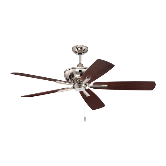
DUN52PLN5
E192641
net weight of fan: 18.32 lb (8.31 kg)
READ THESE INSTRUCTIONS AND
AND SAVE THEM FOR FUTURE USE
Table of Contents:
Safety Tips. pg. 1
Unpacking Your Fan. pg. 2
Parts Inventory. pg. 2
Installation Preparation. pg. 3
Hanging Bracket Installation. pg. 3
Fan Assembly. pgs. 4 - 5
Wiring. pg. 6
Canopy Assembly. pg. 7
Blade Assembly. pg. 7
Switch Housing Assembly pg. 8
Testing Your Fan. pg. 9
Troubleshooting. pg. 10
Parts Replacement. pg. 10
Warranty. pg. 10
PRINTED IN CHINA
Advertisement
Table of Contents

Related Manuals for Ellington DUN52PLN5


Summary of Contents for Ellington DUN52PLN5
-
Page 1: Table Of Contents
READ THESE INSTRUCTIONS AND AND SAVE THEM FOR FUTURE USE Installation Guide For Model: DUN52PLN5 Table of Contents: Safety Tips. pg. 1 Unpacking Your Fan. pg. 2 Parts Inventory. pg. 2 Installation Preparation. pg. 3 Hanging Bracket Installation. pg. 3 Fan Assembly. -
Page 2: Safety Tips
SAFETY TIPS. WARNING: To reduce the risk of electrical shock, turn off the electricity to the fan at the main fuse box or circuit panel before you begin the fan installation or before servicing the fan or installing accessories. READ ALL INSTRUCTIONS AND SAFETY INFORMATION CAREFULLY BEFORE INSTALLING YOUR FAN AND SAVE THESE INSTRUCTIONS. -
Page 3: Unpacking Your Fan
1. Unpacking Your Fan. Carefully open the packaging. Remove items from Styrofoam inserts. Remove motor housing and place on carpet or Styrofoam to avoid damage to finish. Do not discard fan carton or Styrofoam inserts should this fan need to be returned for repairs. -
Page 4: Installation Preparation
3. Installation Preparation. blade edge To prevent personal injury and damage, ensure 7 feet inches that the hanging location allows the blades a (2.13 m) (76 cm) clearance of 7 feet (2.13 m) from the floor and 30 in (76 cm) from any wall or obstruction. This fan is suitable for room sizes up to 400 square 12 ft. -
Page 5: Fan Assembly. Pgs
5. Fan Assembly If you wish to extend the hanging length of your set screw set screw hole fan, you must remove the hanging ball from the stop pin downrod provided to use with an extended downrod (sold separately). [If you wish to use the downrod provided, please proceed to instructions hanging ball following the dotted line below.]... - Page 6 5. Fan Assembly. (cont.) With the hanging bracket secured to the safety cable loop outlet box and able to support the fan, you are wood ceiling now ready to hang your fan. Grab the fan joist firmly with two hands. Slide downrod through opening in hanging bracket and let hanging wood screw ball rest on the hanging bracket.
-
Page 7: Wiring
6. Wiring. white supply wire CAUTION: Be sure outlet box is properly grounded ground (green or bare) and that a ground wire (GREEN or Bare) is present. black supply wire Make sure all electrical connections comply with from ceiling Local Codes or Ordinances and the National wire Electrical Code. -
Page 8: Canopy Assembly
7. Canopy Assembly. Temporarily raise canopy to hanging bracket to hanging determine which 2 screws in hanging bracket bracket align with slotted holes in canopy, and then lower canopy and partially loosen these 2 screws. Remove the other 2 screws and set aside. Now, lift canopy to hanging bracket again, aligning slotted holes in canopy with loosened screws in hanging bracket. -
Page 9: Switch Housing Assembly
9. Switch Housing Assembly. 9. Switch Housing Assembly. motor housing Remove 3 screws from outer edge of switch housing plate (save screws for later use). Remove 1 screw from fitter plate on underside of motor and partially loosen the other 2 screws. -
Page 10: Testing Your Fan
motor 10. Testing Your Fan. housing It is recommended that you test fan before finalizing installation. Restore power from circuit box and light switch (if applicable). Test fan speeds with the pull chain. Start at the OFF position (no blade movement). First pull will set the fan to HI. -
Page 11: Troubleshooting
Return fan, shipping prepaid, to 2. Verify that reverse switch is set completely in Craftmade/Ellington. We will repair or ship you a either direction. replacement fan, and we will pay the return shipping cost. - Page 12 LEER ESTAS INSTRUCCIONES Y GUARDARLAS PARA UTILIZACION FUTURA GUARDARLAS PARA UTILIZACION FUTURA Guía de instalación Para modelo: DUN52PLN5 Indice de materias: Sugerencias de seguridad. Pág. 1 Desempaquetado del ventilador. Pág. 2 Inventario de piezas. Pág. 2 Preparación para la instalación. Pág. 3 Instalación del soporte de montaje.
- Page 13 SUGERENCIAS DE SEGURIDAD. ADVERTENCIA: Para evitar la posibilidad de una descarga eléctrica, desconectar la corriente en la caja de fusibles principal o el interruptor protector antes de iniciar la instalación del ventilador o antes de repararlo o instalar accesorios. LEER TODAS LAS INSTRUCCIONES E INFORMACION DE SEGURIDAD CUIDADOSAMENTE ANTES DE INSTALAR SU VENTILADOR Y GUARDAR ESTAS INSTRUCCIONES.
- Page 14 1. Desempaquetado del ventilador. Abrir el empaque cuidadosamente. Sacar los artículos del embalaje. Sacar el motor y ponerlo en una alfombra o en el embalaje para evitar rayar el acabado. Guardar la caja de cartón o el empaquetamiento original en caso de que tenga que mandar el ventilador para alguna reparación.
- Page 15 3. Preparación para la instalación. borde del aspa 76 cm Para prevenir daño corporal y otros daños, estar seguro de que el lugar en donde va a colgar el ventilador le 2,13 m pulg.) permite un espacio libre de 2,13 m (7 pies) entre las (7 pies) puntas de las aspas y el piso y 76 cm (30 pulg.) entre las aspas y cualquier pared u otra obstrucción.
- Page 16 5. Ensamblaje del ventilador. agujero para el tornillo tornillo perno de fijación Si usted desea extender la longitud colgante del de fijación de tope ventilador, usted tendrá que quitar la bola que sirve para colgar del tubo provisto para usarla con un tubo más largo (a la venta por separado).
- Page 17 5. Ensamblaje del ventilador. (cont.) bucle del cable Ya que esté sujetado el soporte de montaje a de seguridad viga de la caja de salida y capaz de apoyar el madera ventilador, usted está listo para colgar el ventilador. Agarrar el ventilador firmemente tornillo para madera con las dos manos.
- Page 18 6. Instalación eléctrica. alambre conductor blanco toma de tierra PRECAUCION: Asegurarse de que la caja de salida (verde o pelada) alambre conductor negro esté conectada a tierra como es debido y que exista un conductor a tierra (VERDE o pelado). del techo Asegurarse de que toda conexión eléctrica cumpla conector...
- Page 19 7. Colocación de la cubierta decorativa. soporte de Temporalmente subir la cubierta decorativa al soporte de montaje montaje para determinar cuáles 2 tornillos en el soporte de montaje se alinean con los agujeros con ranura en la cubierta decorativa, y luego bajar la cubierta decorativa y parcialmente aflojar dichos tornillos.
- Page 20 9. Instalación de la caja de encendido. bastidor del motor Quitar los 3 tornillos en el borde exterior de la placa de la caja de encendido (guardarlos para uso más adelante). Quitar 1 tornillo de la placa de conexión en la parte inferior del motor y aflojar los otros 2 tornillos.
- Page 21 10. Verificación del funcionamiento del ventilador. Se le recomienda poner el ventilador a prueba antes de terminar la instalación. Regresar la corriente de bastidor electricidad en el cortacircuitos y encender el del motor interruptor de la luz en la pared (si se aplica). Verificar las velocidades del ventilador con la cadena de encendido.
- Page 22 Craftmade/Ellington. Nosotros repararemos el motor al comprador o le enviaremos uno de reemplazo y Craftmade/Ellington pagará los gastos de envío de regreso. Problema: El ventilador se tambalea. GARANTIA LIMITADA DE 6 AÑOS hasta DE POR VIDA: Soluciones: CRAFTMADE/ELLINGTON reparará...
Need help?
Do you have a question about the DUN52PLN5 and is the answer not in the manual?
Questions and answers