
Related Manuals for Pro's Kit MT-1217


Summary of Contents for Pro's Kit MT-1217
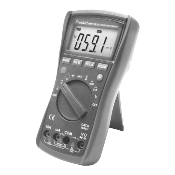
- Page 1 MT-1217 3-3/4 Autorange Digital Multimeter User’s Manual Edition 2013 ©2013 Copyright by Prokit’s Industries Co., Ltd.
-
Page 2: Table Of Contents
Contents General-------------------------------------------------------------------------1 Open-Package Inspection-------------------------------------------------2 Safety Note -------------------------------------------------------------------2 Instrument Panel& Button Function Description----------------------5 Other Functions---------------------------------------------------------------6 Property-------------------------------------------------------------------------6 Instrument Maintenance---------------------------------------------------16 Fault Elimination-------------------------------------------------------------17 General This product is equipped with the LCD display of text height 20mm, is a 3 3/4 digital multimeter which has the merits of clear reading, stable performance and high reliability. -
Page 3: Open-Package Inspection
Open-package Inspection Open the package box and take out the meter, check carefully if the following accessories are absent or damaged. If there is any absence or damage, please contact the distributor immediately. Digital multimeter 1 PC User’s manual 1 copy Test leads 1 pair Temperature Probe (K-Thermocouple) - Page 4 Don’t use other unconfirmed or disapproved battery to replace the battery inside the meter. Only the same model or same electrical specification battery can be replaced. Before the replacement, the test lead must be removed from the measuring point to ensure there is no longer any signal at the input terminal.
-
Page 5: Instrument Panel& Button Function Description
12. When “ ” is shown on LCD display, please replace battery immediately to ensure the measurement precision. 13. It is not allowed to insert the test lead into the current terminal to measure voltage! 14. Please don’t change the circuits of the meter freely for fear that the meter is damaged and the safety be endangered. -
Page 6: Other Functions
3.3 HOLD: date hold 3.4 REL △(Relative Value Measurement): The relative value measurement of Capacity function could be conducted by pressing this button 3.5 Select(Function Switch): Press this button, the function could switch between resistance, capacity and ; AC/DC current。 3.6 LCD backlight button 4. - Page 7 1-3 Measuring Method: Dual integral A/D converter 1-4 Sampling Rage: Approx. 3 times / sec. 1-5 Over Range Indication: Display “OL” 1-6 Low Battery Indication: “ ” symbol appears; 1-7 Operation Environment: (0~40)˚C Relative Humidity:<80% 1-8 Storage Environment: (0~50)˚C Relative Humidity:<80% 1-9 Power: a 9V battery (NEDA1604/6F22 or equivalent) 1-10Dimension (size): 182×90×46mm 1-11 Weight: Approx.
- Page 8 Range Accuracy Resolution 400mV ±(0.5%+4d) 100uV 10mV 400V 100mV 1000V ±(1.0%+6d) Input Impedance: 10MΩ . Overload Protection: 1000V DC or AC peak value 2-2-2. ACV A) Insert black test lead into the hole of “COM” and red test lead into “...
- Page 9 Input Impedance: 10MΩ . Overload Protection: 1000V DC or 750 AC peak value. Frequency Response: (50~200) Hz Display: Average value response (RMS of sine wave). 2-2-3. DCA A) Insert the black test lead into the “COM” input terminal and red test lead into the “mA “...
- Page 10 2-2-4. ACA A) Insert the black test lead into the “COM” input terminal and red test lead into the “mA “input terminal. (Max 400mA), or “10A” input terminal (Max 10A). B) Rotate function switch to Current setting. Press “SELECT” button to select the AC measurement mode. Then connect the test lead to the tested circuit in serial, the tested current value and the current polarity of the point where the red test lead is contacted will be displayed on the screen...
- Page 11 2-2-5. Resistance (Ω) A) Insert the black test lead into “COM” terminal and red test lead into “ “terminal. B) Rotate the Range to “Ω” setting. the initial state of the meter is in automatic range status, which shows “AUTO” symbol C) Connect the two test leads to the tested resistor.
- Page 12 WARNING: DO NOT input any voltage at resistance range for safety! 2-2-6.Diode and Continuity Test A) Insert the black test lead to “COM” terminal and the red test lead to “ ” terminal. (The polarity of red test lead is“+”). B) Rotate the Range to “...
- Page 13 • Overload Protection: 250V DC or AC Peak Value. WARNING: DO NOT input any voltage at this range for safety! 2-2-7. Capacity (F) A) Rotate function switch to “ “setting. B) Or rotate the Range to “Ω“setting. Press “SELECT” button to select the capacity measurement mode.
- Page 14 2-2-8. Frequency (Hz) A) Test volt frequency, connect test leads and shielded cable respectively to “COM” terminal and “ ” terminal. B) Rotate function switch to “ “ gear. Connect test leads and the cable to the signal source or the tested load. The tested signal will show on the screen.
- Page 15 Caution: 1. When the input terminal is open-circuit, it will display the “OL” symbol on the screen. 2. Don’t change the temperature probe at random, or the value accuracy could not be guaranteed. 3. Don’t measure voltage at temperature range. Range Accuracy Resolution...
-
Page 16: Instrument Maintenance
Instrument Maintenance This is a precision instrument and the user shall not modify the electric circuit as well. 1. Keep the instrument away from water, dust and shock. 2. Do not store and operate the meter under the condition of high temperature, high humidity, combustible, explosive and strong magnetic place. -
Page 17: Fault Elimination
Fault Elimination If the instrument could not work properly, please try the following tips to solve some general problems. If the problems still exist, please contact the maintenance center or the distributor. Solution Fault Turn on power. No Display Or Replace battery symbol appearance Replace battery. - Page 18 目 錄 一.概述----------------------------------------------------------------------------------------18 二.開箱檢查---------------------------------------------------------------------------------18 三.安全注意事項---------------------------------------------------------------------------19 四.儀錶面板及按鍵功能說明-----------------------------------------------------------20 五.其他功能--------------------------------------------------------------------------------- 21 六.特性--------------------------------------------------------------------------------------- 21 七.儀錶保養--------------------------------------------------------------------------------- 29 八.故障排除--------------------------------------------------------------------------------- 30 一、概述 MT-1217 是一款性能穩定、高可靠性 3 3/4 位元數字多用錶。儀錶採用 20mm 字高 LCD 顯示器,讀數清晰。 可用來測量直流電壓、交流電壓、直流電流、交流電流、電阻、溫度、電 容、頻率/占空比、二極體及通斷測試。同時還設計有單位符號顯示、自動 /手動量程轉換、自動斷電及報警功能。該錶功能齊全,測量準確度高,使 用方便,是實驗室、工廠、無線電愛好者及家庭的理想工具。 二、開箱檢查 打開包裝箱取出儀錶,仔細檢查以下附件是否缺少或損壞, 如有缺少或損壞請立即與經銷商聯繫。 ● 數字多用錶 一台 ● 使用說明書 一本 ● 錶棒 一付...
- Page 19 任何信號。 在進行電氣測量時,身體切勿直接接觸大地,不要接觸可能存在地電勢 裸露的金屬端子、輸出口、引線夾等。通常使用乾燥的衣服、膠鞋、 膠墊以及其他絕緣材料,保持你的身體與大地絕緣。 不要在高溫、高濕、易燃、易爆和強磁場環境中存放及使用。 測量超過儀錶所允許的極限電壓值有可能損壞儀錶和危及操作人員 的安全。在儀錶面板上標有儀錶所允許測量的極限電壓值切勿測量超 過此標準的安全,請勿輸入超過規定的極限值,以防電擊和損壞儀錶。 當錶棒線插入電流插座時切勿測量任何電壓以免損壞儀錶和危及操 作人員的安全。 不要嘗試校準或維修儀錶。的確有需要時必須有專門培訓或認可的有 資格專業人員才能進行。 在測量時功能/量程選擇開關必需置於正確的量程檔位,在轉換功能/量 程選擇開關時,請一定要先將錶棒線與被測物件斷開,確保輸入端沒任 何信號輸入。嚴禁在測量進行中轉換功能/量程選擇開關。 當 LCD 顯示“ "時,請及時更換電池以確保測量精度。 不允許在電流檔去測量電壓! 請不要隨意改變儀錶線路,以免損壞儀錶和危及安全。 安全符號說明: 警告! 直流電壓 雙重絕緣 交流電壓 直流電流 保險絲 交流電流 符合歐洲工 低電壓指示 會指令 四、儀錶面板及按鍵功能說明 1. 儀錶型號 2. 液晶顯示器:顯示儀錶測量的數值及單位 3. 功能按鍵說明 3.1. Hz/% (頻率/占空比):交流電壓位, 觸發此鍵, 可進行頻率/占...
- Page 20 3.3. HOLD︰測量數據保持. 3.4. REL △(相對值測量):在電容檔 觸發此鍵, 可進行相對值測量模式. 3.5. SELECT: 選擇電阻, 電容, 二極管, 通 斷測量功能及電流檔 DC/AC 切換 3.6. LCD 顯示背光按鍵, 觸發此鍵控制開, 閉背光. 4. 旋鈕開關:用於改變測量功能及量程。 5. 輸入插孔 5.1. 10A“+"輸入插孔 5.2. mA“+"電流輸入, 溫度“+"輸入, 電容輸入以及電晶體輸入插孔 5.3. 電壓、二極體、電阻、頻率、蜂鳴器輸入插座 5.4. COM 公共插孔: 電流、電壓、二極體、電晶體、電阻、電容、頻率、 蜂鳴器、溫度的“-"輸入插孔 五、其他功能 自動關機 在測量過程中,功能按鍵和撥盤開關在...
- Page 21 功能 有/無 直流電壓 DCV 有 交流電壓 ACV 有 直流電流 DCA 有 交流電流 ACA 有 電阻 Ω 有 電容 CAP 有 頻率 Hz 有 二極體/通斷 有 溫度 °C 有 2-3-1.直流電壓(DCV) A). 將旋鈕開關轉至“ "檔 B). 儀錶初始為自動量程狀態,顯示“AUTO"符號 C.) 將測試錶棒接觸測試點,紅錶棒所接的該點電壓與極性顯示在螢幕 上。 注意: 1. 測量電壓切勿超過 1000V,超過則有損壞儀錶電路的危險。 2.
- Page 22 量程 準確度 分辨力 ±(0.8%+6d) 10mV 400V 100mV 750V ±(1.0%+10d) ‧輸入阻抗:10MΩ。 ‧超載保護:1000V 直流或 750V 交流峰值; ‧頻率回應:(50~200)Hz ‧顯 示:平均值響應(以正弦波有效值校準) 。 2-3-3.直流電流(DCA) 將黑錶棒插入“COM"插孔,紅錶棒插入“mA"插孔(最大為 400mA) ,或插入“10A"插孔中(最大為 10A) 將旋鈕開關轉至電流檔,儀錶初始為自動量程狀態,顯示“DC"符 號,然後將儀錶的錶棒串入被測電路中,被測電流值及紅色錶棒點的 電流極性將同時顯示在螢幕上。 注意: 如 LCD 顯示“OL",表明已超過量程範圍,需將量程開關轉至較高 一檔。 最大輸入電流為 400mA 或者 10A(視紅錶棒插入位置而定) ,超過額 定的電流會將保險絲熔斷,甚至損壞儀錶。 量程 準確度 分辨力 400uA ±(1.0%+10d) 0.1uA...
- Page 23 注意: 如 LCD 顯示“OL",表明已超過量程範圍,需將量程開關轉至較高 一檔。 最大輸入電流為 400mA 或者 10A(視紅錶棒插入位置而定) ,超過額 定的電流會將保險絲熔斷,甚至損壞儀錶。 量程 準確度 分辨力 400uA ±(1.5%+10d) 0.1uA 4000uA 40mA 10uA 400mA 100uA ±(2.0%+15d) 10mA ±(2.5%+15d) 10mA ‧最大測量壓降:滿量程 mA 為 0.4V,A 為 100mV; ‧最大輸入電流:10A(不超過 15 秒) 。 ‧超載保護:0.4A/250V 自恢復保險絲,10A/250V 保險管。 ‧頻率回應:10A 量程為(50~200)Hz。 2-3-5.電阻(Ω) 將黑錶棒插入“COM"插孔,紅錶棒插入“...
- Page 24 ‧超載保護:250V 直流或交流峰值; ‧注意事項:在使用 400Ω 量程時,應先將錶棒短路,測得引線電阻, 然後在實測中減去 警告:為了安全在此量程禁止輸入電壓值! 2-3-6.二極體及通斷測試 將黑錶棒插入“COM"插孔,紅錶棒入“ "插孔(注意紅錶棒極 性為“+"極) 。 將旋鈕開關轉至““Ω"檔 , 按動“SELECT"鍵選擇二極體測量方式 正向測量:將紅錶棒接到被測二極體的正極,黑錶棒接到被測二極體 的負極,顯示器即顯示二極體正向壓降的近似值。 反向測量:將紅錶棒接到被測二極體的負極,黑錶棒接到被測二極體 的正極,顯示器顯示“OL"字樣。 完整的二極體測試包括正反向測量,如果測試結果與上述不符,說明 二極體是壞的。 按動“SELECT"鍵選擇通斷測量方式。 將錶棒連接到待測線路的兩點,如果內置蜂鳴器發聲,則兩點之間電 阻值低於約 50Ω,則內置蜂鳴器發聲。 量程 顯示值 測試條件 二極體正向壓降 正向直流電流 0.5mA 反向電壓約 1.5V 蜂鳴器發聲長響 , 測 開路電壓約 0.5V 試兩點阻值約 50Ω ‧超載保護:250V 直流或交流峰值;...
- Page 25 400nF ±(3.5%+8d) 100pF 4μF ±(3.5%+8d) 20μF ±(3.5%+8d) 10nF 警告:為了安全在此量程禁止輸入電壓值! 2-3-8.頻率(Hz) 1. 測試電壓頻率時,將錶棒或遮罩電纜接入“COM"和“ "輸入端; 2. 將旋鈕開關轉至“ "檔,將錶棒或電纜跨接在信號源或被測負載 上,被測信號的頻率顯示在螢幕上。 注意: 輸入超過 10V 交流有效值時,可以讀數,但可能超差; 在雜訊環境下,測量小信號時最好使用屏壁電纜; 測量高電壓的頻率時,請選擇 ACV 檔,再按 Hz/%按鍵進入頻率測量 狀態 禁止輸入超過 250V 直流或交流峰值的電壓,以免損壞儀錶。 程量 準確度 分辨力 400Hz ±(0.5%+10d) 0.1Hz 4kHz 20kHz 10Hz 0.1-99.9% 僅供參考...
- Page 26 1. 將功旋鈕開關轉至 HFE 檔位. 2. 將附件晶體管測試座插入 COM"和“mA"插孔中 3. 依據待測試的晶體管型號, 將各引腳插入對應的測試孔, 屏幕顯示相應 的測量數值。 量程 顯示值 測試條件 hFE NPN 或 PNP 0~1000 基礎電流約 10uA, Vce 約為 3V 警 告:為了安全在此量程禁止輸入電壓值! 七、儀錶保養 該儀錶是一台精密儀器,使用者不要隨意更改電路。 請注意防水、防塵、防摔 不宜在高溫高濕、易燃易爆和強磁場的環境下存放、使用儀錶 請使用濕布和溫和的清潔劑清潔儀錶外表,不要使用研磨劑及酒精等 烈性溶劑 如果長時間不使用,應取出電池,防止電池漏液腐蝕儀錶 注意 9V 電池使用情況,當螢幕顯示出“ "符號時,應更換電池, 步驟如下: 5-1. 卸下固定電池盒的螺絲,取出電池盒 5-2.
- Page 27 中國地區產品保固卡 購買日期 店章 公司名稱 聯絡電話 電子郵箱 聯絡地址 MT-1217-C 產品型號 在正常使用情況下,自原購買日起 12 個月免費維修保證(不含耗材、 ※ 消耗品) 。 ※ 產品保固卡需蓋上店章、日期章,其保固效力始生效。 ※ 本卡請妥善保存,如需維修服務時,請出示本卡以為證明。 ※ 保固期滿後,屬調整、保養或是維修性質之服務,則酌收檢修工時費 用。若有零件需更換,則零件費另計。 產品保固說明 保固期限內,如有下列情況者,維修中心則得酌收材料成本或修理費(由 本公司維修人員判定): ‧ 對產品表面的損傷,包括外殼裂縫或刮痕 ‧ 因誤用、疏忽、不當安裝或測試,未經授權打開產品修理,修改 產品或者任何其他超出預期使用範圍的原因所造成的損害 ‧ 因事故、火災、電力變化、其他危害,或自然災難所造成的損害。 非服務保證內容: ‧ 機件本體外之消耗品:如電池...等消耗品 ‧ 機件本體之外之附配件:如耳機麥克風,電源供應器,記憶卡, CD 等附配件。...
- Page 28 ©2013 Prokit’s Industries Co., LTD. All rights reserved 2013001(T)
Need help?
Do you have a question about the MT-1217 and is the answer not in the manual?
Questions and answers