Table of Contents
Advertisement
Advertisement
Table of Contents

Related Manuals for OHAUS Ranger 7000 R71MHD3


Summary of Contents for OHAUS Ranger 7000 R71MHD3
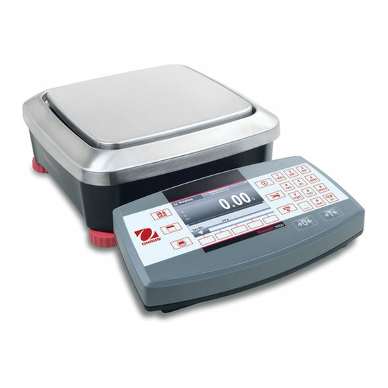
- Page 1 ® Ranger 7000 Scale Service Manual...
-
Page 3: Table Of Contents
5 PARTS LISTS & DIAGRAMS TERMINAL SPARE PARTS BASE SPARE PARTS (R71MD3 and R71MD6) BASE SPARE PARTS (R71MD15 and R71MD35) BASE SPARE PARTS (R71MHD3 and R71MHD6) BASE SPARE PARTS (R71MHD15 and R71MHD35) ® Ohaus Corporation www.ohaus.com Ranger 7000 Service Manual... - Page 4 Off Center Load Mass Values Terminal Spare Parts Base Spare Parts (R71MD3 and R71MD6) Base Spare Parts (R71MD15 and R71MD35) Base Spare Parts (R71MHD3 and R71MHD6) Base Spare Parts (R71MHD15 and R71MHD35) Interface Command List ® Ranger 7000 Service Manual Ohaus Corporation www.ohaus.com...
- Page 5 TABLE OF CONTENTS ® Ohaus Corporation www.ohaus.com Ranger 7000 Service Manual...
-
Page 6: Getting Started
INTRODUCTION This service manual contains the information needed to perform routine maintenance and service ® on the Ohaus Ranger 7000 Series scales. Familiarity with the scale’s Instruction Manual is assumed. The contents of this manual are contained in five chapters: Chapter 1 - Getting Started –... -
Page 7: Tools And Test Equipment Required
• SPECIFICATIONS ® Specifications for the Ohaus Ranger 7000 Scales are listed in Table 1-1. When a scale has been serviced, it must meet the specifications listed in the table. Before servicing the scale, determine what specifications are not met. -
Page 8: Specifications
11 x 11 x 4.5 inch 14.9 x 18.4 x 5 inch Net weight 7.2 kg / 16 lb 10.9 kg / 24 lb 14.4 kg / 31.7 Shipping weight 9.2 kg / 20.3 lb ® Ohaus Corporation www.ohaus.com Ranger 7000 Series Service Manual... - Page 9 17.4 x 16.5 x 4.5 inch 14.9 x 18.4 x 5 inch Net weight 6.8 kg / 15 lb 9.9 kg / 21.8 lb 13.4 kg / 29.5 Shipping weight 8.5 kg / 18.7 lb ® Ranger 7000 Series Service Manual Ohaus Corporation www.ohaus.com...
-
Page 10: Operation
OPERATION 1.5.1 Overview of the Controls ® Ohaus Corporation www.ohaus.com Ranger 7000 Series Service Manual... - Page 11 ® Ranger 7000 Series Service Manual Ohaus Corporation www.ohaus.com...
-
Page 12: Principle Functions And Main Menu
1.5.2 Principle Functions and Main Menu. 1-2 Menu and Screen Navigation ® Ohaus Corporation www.ohaus.com Ranger 7000 Series Service Manual... -
Page 13: Diagnostic Guide
Capacity and readability 3000g x 0.05g Software Revision “Terminal” / “Base” Version 1.00 / 0.14 The scale software can also be retrieved by sending a “PV” command via the RS232 or other interface. ® Ranger 7000 Series Service Manual Ohaus Corporation www.ohaus.com... -
Page 14: Diagnostic Guide
Average Piece Weight warning message too small. (Warning) Reference Error Unacceptable reference Reference Weight too weight message small. The weight on the pan is too small to define a valid reference weight. ® Ohaus Corporation www.ohaus.com Ranger 7000 Series Service Manual... - Page 15 NOTE: If more than one symptom is observed, approach one area at a time, and remember that the symptoms may be interrelated. If a problem arises that is not covered in this manual, contact Ohaus Corporation for further information. ®...
-
Page 16: Maintenance / Repair Procedures
MAINTENANCE / REPAIR PROCEDURES PREVENTIVE MAINTENANCE Ohaus scales are precision instruments and should be carefully handled, stored in a clean, dry, dust-free area, and cleaned periodically. Follow these precautionary steps: When a scale has had chemicals or liquids spilled on it, all exterior surfaces should be •... -
Page 17: Opening The Scale
2. Detach the display terminal from the base by pressing both release buttons at the same time as show below picture. After that pull the Terminal towards you (outward) until the Terminal is detached from the base as show below. ® Ranger 7000 Series Service Manual Ohaus Corporation www.ohaus.com... -
Page 18: Detaching The Base Rs422 Cable From The Terminal
3.3.2 Detaching the base RS422 cable from the Terminal. 1. Dismantle the base RS422 cable from the Terminal. 2. Removing the docking bracket from the Terminal. ® Ohaus Corporation www.ohaus.com Ranger 7000 Series Service Manual... - Page 19 3. Flip the Terminal around locate the 3 screws as shown and remove the screws which are mounting the bracket to the Terminal as shown below and separate the docking bracket from the Terminal. ® Ranger 7000 Series Service Manual Ohaus Corporation www.ohaus.com...
-
Page 20: Dismantling The Terminal Housing
4 screws are located underneath the rubber cover at 4 corners of the bottom housing. • Remove the rubber cover and you will be able to locate and remove the 4 hidden screws. ® Ohaus Corporation www.ohaus.com Ranger 7000 Series Service Manual... - Page 21 After that carefully lift up the top housing, DO NOT remove the top housing completely away from the bottom housing because the Terminal keypad overlay ribbon cable and TFT display ribbon cable are still attached with the Terminal main PCBA. ® Ranger 7000 Series Service Manual Ohaus Corporation www.ohaus.com...
- Page 22 Connector lock with ribbon cable attaches Connector open with TFT ribbon cable remove. 4. Disconnect the keypad overlay ribbon cable from the Terminal PCBA by unfasten the connector as shown in below pictures. ® Ohaus Corporation www.ohaus.com Ranger 7000 Series Service Manual...
- Page 23 Shift the connector outward Connector open and keypad overlay cable remove 5. Both bottom and top Terminal housing are now separated. ® Ranger 7000 Series Service Manual Ohaus Corporation www.ohaus.com...
-
Page 24: Opening The Base Module
Complete set of Large Housing base Weighing pan removed 3. Remove the 2 screws securing the Spider to the top housing. Location of 2 screws securing the Spider with base top housing. ® Ohaus Corporation www.ohaus.com Ranger 7000 Series Service Manual... - Page 25 Spider removed from base top housing. 4. Remove 6 screws securing the base top housing and bottom housing. Location of the first 6 screws. ® Ranger 7000 Series Service Manual Ohaus Corporation www.ohaus.com...
- Page 26 Remove the 2 screws securing the LFT cover. screw expose, by removing this screw you will be able to dismantle the base top housing from the base bottom housing. R71 SG Base top housing removed. ® Ohaus Corporation www.ohaus.com Ranger 7000 Series Service Manual...
-
Page 27: Opening R71 Small Housing Mode
7. Remove the weighing Pan and Wind Ring from the base. Complete set of MFR base Weighing pan removed Wind Ring removed. 8. Remove the 2 screws securing the Spider to the top housing. ® Ranger 7000 Series Service Manual Ohaus Corporation www.ohaus.com... - Page 28 Location of 2 screws securing the Spider with base top housing. Spider removed from base top housing. 9. Remove 5 screws securing the base top housing and bottom housing. ® Ohaus Corporation www.ohaus.com Ranger 7000 Series Service Manual...
- Page 29 LFT cover. Remove the 2 screws securing the LFT cover. screw expose, by removing this screw you will be able to dismantle the base top housing from the base bottom housing. ® Ranger 7000 Series Service Manual Ohaus Corporation www.ohaus.com...
- Page 30 ® Ohaus Corporation www.ohaus.com Ranger 7000 Series Service Manual...
-
Page 31: Replacing Mfr Load Cell, R71
R71 load cell type MFR. 3. Remove the cable connecting the Base PCBA with MFR load cell as shown below. 4. Remove the Red and White cable connecting the base PCBA with LFT PCBA. ® Ranger 7000 Series Service Manual Ohaus Corporation www.ohaus.com... - Page 32 5. Remove the cable connected from the load cell Auto Calibration motor PCBA to the main PCBA as shown below. ® Ohaus Corporation www.ohaus.com Ranger 7000 Series Service Manual...
- Page 33 Take special care to route the wires and cables according to their original positions. Proper routing is important for RFI/ESD performance. Ensure that the wires or cables are not pinched during re- assembly. ® Ranger 7000 Series Service Manual Ohaus Corporation www.ohaus.com...
-
Page 34: Replacing Sg Load Cell, R71
1. Locate the 2 screws securing the SG load cell with the base bottom housing. R71 load cell type SG. 2. Remove the cable connecting the Base PCBA with SG load cell as shown below. ® Ohaus Corporation www.ohaus.com Ranger 7000 Series Service Manual... - Page 35 Take special care to route the wires and cables according to their original positions. Proper routing is important for RFI/ESD performance. Ensure that the wires or cables are not pinched during re- assembly. ® Ranger 7000 Series Service Manual Ohaus Corporation www.ohaus.com...
-
Page 36: Replacing The Printed Circuit Board Assemblies (Pcba)
Location of the 4 screws and 8PIN connector on the Terminal PCBA. B) Remove the 8PIN connector by gently pulling up the connector. Showing 8PIN Connector attached and detached from Terminal PCBA. ® Ohaus Corporation www.ohaus.com Ranger 7000 Series Service Manual... - Page 37 C) Removing the 2 screws securing the RS232 Port to the bottom housing. R71 RS232 port located behind the Terminal. 2 screws securing the RS232 port against the Terminal housing removed. (Remember to place back these 2 screws after repairing) ® Ranger 7000 Series Service Manual Ohaus Corporation www.ohaus.com...
-
Page 38: Remove The Tft Pcb
A) Remove the two screws holding the TFT in place as shown below. Location of the 2 screws holding the TFT in place against the Terminal Top housing. (Note the position of the two RED holders) ® Ohaus Corporation www.ohaus.com Ranger 7000 Series Service Manual... - Page 39 B) Gently remove the TFT from the top housing and place in a secure area. *When re-installing the TFT PCB make sure the surface on the TFT PCB and Top housing is clean and free from dust and debris. ® Ranger 7000 Series Service Manual Ohaus Corporation www.ohaus.com...
- Page 40 TFT PCB removed from Terminal Top housing. R71, 4.3" TFT Display PCB P/N: 30095940 ® Ohaus Corporation www.ohaus.com Ranger 7000 Series Service Manual...
-
Page 41: Removing Mfr Main Pcba
B Cable, RS422 Cable from main PCBA to R71 Display Terminal. C Cable, Cable from main PCBA to LFT PCBA. D Cable, Cable from MFR cell to main PCBA. E Cable, Cable from AutoCal motor PCBA to main PCBA. ® Ranger 7000 Series Service Manual Ohaus Corporation www.ohaus.com... - Page 42 Location of the 2 screws securing the main PCBA to the bottom housing. Screw at Lock position Screw at Un-Lock position Once you set the two screws in Un-Lock position you will be able to remove the Main PCBA from the bottom housing. ® Ohaus Corporation www.ohaus.com Ranger 7000 Series Service Manual...
-
Page 43: Removing Mfr Lft Pcba
C Cable, Cable link from LFT PCBA to Main PCBA. D Cable, Black/While cable link from LFT PCBA to AC Adapter. E Cable, Red/White Cable from LFT PCBA to Main PCBA. ® Ranger 7000 Series Service Manual Ohaus Corporation www.ohaus.com... - Page 44 Picture shows 5 cables removed, location of the 2 screws. Screw at Lock position Screw at Un-Lock position Once you set the two screws in Un-Lock position you will be able to remove the LFT PCBA from the bottom housing. ® Ohaus Corporation www.ohaus.com Ranger 7000 Series Service Manual...
-
Page 45: Replacing Sg Lft Pcba
C Cable, Cable link from LFT PCBA to Main PCBA. D Cable, Black/While cable link from LFT PCBA to AC Adapter. E Cable, Red/Black Cable from LFT PCBA to Main PCBA. ® Ranger 7000 Series Service Manual Ohaus Corporation www.ohaus.com... - Page 46 Picture shows 5 cables removed, location of the 2 screws. Screw at Lock position Screw at Un-Lock position Once you set the two screws in Un-Lock position you will be able to remove the LFT PCBA from the bottom housing. ® Ohaus Corporation www.ohaus.com Ranger 7000 Series Service Manual...
-
Page 47: Replacing Sg Main Pcba
Model R71MD15 is shown below. 1. Remove 4 cables from the main PCBA. 2. Remove the 3 screws securing the main PCBA with the base bottom housing. R71 load cell type SG. ® Ranger 7000 Series Service Manual Ohaus Corporation www.ohaus.com... - Page 48 A Cable, RS422 cable from main PCBA to R71 Display Terminal. B Cable, Cable link from main PCBA to LFT PCBA. C Cable, Red White Cable link from main PCBA to LFT PCBA. D Cable, Load Cell cable. ® Ohaus Corporation www.ohaus.com Ranger 7000 Series Service Manual...
- Page 49 2. After removing the above 4 cables now locate and remove 3 screws which securing the main PCBA to the bottom housing. ® Ranger 7000 Series Service Manual Ohaus Corporation www.ohaus.com...
-
Page 50: Testing
The Analytical models especially need a solid platform, such as a stone table. 4.1 TEST MASSES REQUIRED ® The masses required to test the Ohaus Ranger 7000 scales must meet the requirements of the ASTM or OIML Tolerances listed in the table. Poor quality calibration masses be the can cause of frustrating diagnostics. -
Page 51: Operational Test
If it still does not meet specifications, perform a service calibration, and try again. (See Appendix B for Service Calibration) If the scale does not pass this test, the Load Cell may need to be replaced. ® Ranger 7000 Series Service Manual Ohaus Corporation www.ohaus.com... -
Page 52: Repeatability Test (Non-Approved Models)
3. Remove the mass from the platform. 4. Repeat this test starting at Step 1 until you record a total of ten readings. Fill in the worksheet with the ten (10) readings. ® Ohaus Corporation www.ohaus.com Ranger 7000 Series Service Manual... -
Page 53: Calibration Mass Values
Note: If the scale does not meet specifications, check environmental conditions, ensure that the scale is level, and try again. If it still does not meet specifications, perform a service calibration, and try again. (See Appendix B for Service Calibration). ® Ranger 7000 Series Service Manual Ohaus Corporation www.ohaus.com... -
Page 54: Linearity Test
8. The difference in the weights of the test mass should be within the tolerance in Table 4-2. If the differences are out of tolerance, verify the test conditions and repeat the test. 9. If the scale remains out of tolerance, the Load Cell may need to be replaced. ® Ohaus Corporation www.ohaus.com Ranger 7000 Series Service Manual... -
Page 55: Off-Center Load Test
8. Maximum allowable change in displayed weight readings for each of the four positions can be found in Specifications Tables (Chapter 1). If this maximum is exceeded verify the test conditions and retest the scale. If there is no improvement the load-cell must be replaced. ® Ranger 7000 Series Service Manual Ohaus Corporation www.ohaus.com... -
Page 56: Repeatability Worksheet
Note: In high resolution scales (Class I) it may be necessary to zero or tare between each location. ® Ohaus Corporation www.ohaus.com Ranger 7000 Series Service Manual... -
Page 57: Parts Lists & Diagrams
NOTE: In all cases where a part is replaced, the scale must be thoroughly checked after the replacement is made. The scale MUST meet the parameters of all applicable specifications in this manual. If further technical information is needed, please contact your local Ohaus office, or www.ohaus.com. ® Ranger 7000 Series Service Manual Ohaus Corporation www.ohaus.com... -
Page 58: Terminal Spare Parts
5.1 TERMINAL SPARE PARTS ® Ohaus Corporation www.ohaus.com Ranger 7000 Series Service Manual... - Page 59 SP Overlay R71 Terminal 30095940 SP 4.3" TFT Display R71 Terminal 30095930 SP PCBA, Terminal R71 30103748 SP 8PIN Connector Terminal, R71 30095941 SP Bracket, Docking, R71 30095907 SP Hardware Kit, R71 ® Ranger 7000 Series Service Manual Ohaus Corporation www.ohaus.com...
-
Page 60: Base Spare Parts (R71Md3 And R71Md6)
5.2 BASE SPARE PARTS (R71MD3 and R71MD6) ® Ohaus Corporation www.ohaus.com Ranger 7000 Series Service Manual... -
Page 61: Terminal Spare Parts
30041469 SP Power-Cord KR EX HiCap, R71 30095936 SP RS422 Cable Base R71 30035606 SP Feet Kit R21, R31, V71, V22, V41, R71 30095932 SP Packaging Assembly,SM,R71 30095933 SP Packaging Assembly,LA,SG,R71 30078209 Box,SM,R71 ® Ranger 7000 Series Service Manual Ohaus Corporation www.ohaus.com... -
Page 62: Base Spare Parts (R71Md15 And R71Md35)
5.3 BASE SPARE PARTS (R71MD15 and R71MD35) ® Ohaus Corporation www.ohaus.com Ranger 7000 Series Service Manual... -
Page 63: Base Spare Parts (R71Md3 And R71Md6)
30041469 SP Power-Cord KR EX HiCap, R71 30095936 SP RS422 Cable Base R71 30035606 SP Feet Kit R21, R31, V71, V22, V41, R71 30095932 SP Packaging Assembly,SM,R71 30095933 SP Packaging Assembly,LA,SG,R71 30078209 Box,SM,R71 ® Ranger 7000 Series Service Manual Ohaus Corporation www.ohaus.com... -
Page 64: Base Spare Parts (R71Mhd3 And R71Mhd6)
5.4 BASE SPARE PARTS (R71MHD3 and R71MHD6) ® Ohaus Corporation www.ohaus.com Ranger 7000 Series Service Manual... -
Page 65: Base Spare Parts (R71Md15 And R71Md35)
30041469 SP Power-Cord KR EX HiCap, R71 30095936 SP RS422 Cable Base R71 30035606 SP Feet Kit R21, R31, V71, V22, V41, R71 30095932 SP Packaging Assembly,SM,R71 30095933 SP Packaging Assembly,LA,SG,R71 30078209 Box,SM,R71 ® Ranger 7000 Series Service Manual Ohaus Corporation www.ohaus.com... -
Page 66: Base Spare Parts (R71Mhd15 And R71Mhd35)
5.5 BASE SPARE PARTS (R71MHD15 and R71MHD35) ® Ohaus Corporation www.ohaus.com Ranger 7000 Series Service Manual... -
Page 67: Base Spare Parts (R71Mhd3 And R71Mhd6)
30041469 SP Power-Cord KR EX HiCap, R71 30095936 SP RS422 Cable Base R71 30035606 SP Feet Kit R21, R31, V71, V22, V41, R71 30095932 SP Packaging Assembly,SM,R71 30095933 SP Packaging Assembly,LA,SG,R71 30078209 Box,SM,R71 ® Ranger 7000 Series Service Manual Ohaus Corporation www.ohaus.com... -
Page 68: Accessing The Service Menu
2. By selecting the far right button you will come to the below window screen. 3. Key in Super Password 'OHR71' you will be able to gain access into 'Service Menu'. ® Ranger 7000 Series Service Manual Ohaus Corporation www.ohaus.com... -
Page 69: Creating Userlogin
3. Start keying in your user profile information by selecting the 'add record' button. 4. Key in the 'User' name, 'Password' and 'ConfirmPassword', below show example User (1), Password (123) and ConfirmPassword (123). ® Ohaus Corporation www.ohaus.com Ranger 7000 Series Service Manual... - Page 70 1 to 3 you will be able to gain access into 'Service Menu'. 5. Key in the Super password 'OHR71' and press Enter key you will return back to normal weighing mode. ® Ranger 7000 Series Service Manual Ohaus Corporation www.ohaus.com...
- Page 71 6. Proceed to 'Main Menu' and select 'Maintenance'. ® Ohaus Corporation www.ohaus.com Ranger 7000 Series Service Manual...
-
Page 72: Under Service Menu
• 'RAMP' value- typical value range from 50-80% (varies depends on models) and value should not be 0 or 100%. • Expand – For R and D usage. • Factory Linear Cal – Using external weights to perform linearity calibration, follow screen instruction. ® Ranger 7000 Series Service Manual Ohaus Corporation www.ohaus.com... - Page 73 • Firmware Update – updating base and terminal firmware. Note: When downloading Terminal Software using Ohaus Repair and Service Tool the file is type *.mot. If downloading via the USB host is type *.bin. The software need to be put in the "R71_FW"...
- Page 74 If the USB Flash drive is not plug in you will see the below message. USB flash drive is not connected. Base image found Current Terminal: 1.03 Terminal image found Current Base: 1.00.02 • Format Alibi Memory – Formatting/Erasing Alibi memory. ® Ranger 7000 Series Service Manual Ohaus Corporation www.ohaus.com...
-
Page 75: Maintenance (Diagnostic)
1. Under 'Diagnostic' you will have the below options. • LCD diagnostic – 4 diagnostic test will be perform on the color LCD screen for RED, Green, Blue color test and BackLight Test. ® Ohaus Corporation www.ohaus.com Ranger 7000 Series Service Manual... - Page 76 • 4 key tests- testing the functionality of the keypad membrane, the below 4 keys will be tested during this diagnostic. ® Ranger 7000 Series Service Manual Ohaus Corporation www.ohaus.com...
- Page 77 ® Ohaus Corporation www.ohaus.com Ranger 7000 Series Service Manual...
-
Page 78: Disable 'Service Menu
6.5 Disable 'Service Menu'. 1. Press and hold '0/User' button, you will see the preset User Profiles. 2. By selecting the far right button you will come to the below window screen. ® Ranger 7000 Series Service Manual Ohaus Corporation www.ohaus.com... - Page 79 3. Key in previously set User password example'123' you will disable the 'Service Menu' as shown below. ® Ohaus Corporation www.ohaus.com Ranger 7000 Series Service Manual...
-
Page 80: Appendix A - Communication
PCB replacement. The tool can also be used to communicate with the scale using commands that are listed at the end of the appendix. The latest software service tool and support files are available on the Ohaus DMX site. Please read the Service Tool Instruction Manual (Part Number 30032352) which is also available on Ohaus DMX site. -
Page 81: Rs232 (Db9) Pin Connections
The G/N field is 1 character. 'G' is printed for a gross weight. 'N' is printed for a net weight. • The Message field is 5 left justified characters. • Note: The Termination Characters Carriage Return and Line Feed are appended to the printout. ® Ohaus Corporation www.ohaus.com Ranger 7000 Series Service Manual... -
Page 82: A3.3. Print Out String For Lb:oz Units
The G/N field is 1 character. 'G' is printed for a gross weight. 'N' is printed for a net weight. • The Message field is 5 left justified characters. • Note: The Termination Characters Carriage Return and Line Feed are appended to the printout. ® Ranger 7000 Series Service Manual Ohaus Corporation www.ohaus.com... -
Page 83: Software Installation & Software Selection
APPENDIX B. SOFTWARE SERVICE & REPAIR TOOL INSTRUCTIONS Note: Make sure OHAUS Service & Repair Tools is version V2.1.1.1 or later which is available for down load in DMX under 'Service Software' folder. Software Installation and Software Selection: The OHAUS Software Service & Repair Tool is used for 5 purposes: 1. -
Page 84: Product Selection
The load cell serial number (you need to open the scale and record this information on the load cell.) 2. Contact Ohaus Corporation in Pine Brook NJ, and request the data file to download. Provide the information recorded above. 3. After receiving the data file from Ohaus, continue with the following steps. - Page 85 Figure B-3. Restore EEPROM. Figure B-4. Write Image File. ® Ohaus Corporation www.ohaus.com Ranger 7000 Series Service Manual...
-
Page 86: Com Port Configuration
5. The software will indicate the download progress. When complete, disconnect the power from the back of the scale, then re-connect. 6. Perform Service Calibrations (see Chapter 6). Test the scale. ® Ranger 7000 Series Service Manual Ohaus Corporation www.ohaus.com... -
Page 87: To Replace Load Cell
IDNR number. Carefully select the label that matches exactly the model number of the scale. 9. Get the scale Image File from OHAUS by providing the scale model and serial number. 10. Put the new label on the scale. - Page 88 (AP, EU/GB or US). 17. Enter the IDNR number (xxx.xx.xx.xxxx) from the label on the back of the scale or from the packet label of the new load cell. 18. Click the Start button. ® Ranger 7000 Series Service Manual Ohaus Corporation www.ohaus.com...
-
Page 89: Install New Main Printed Circuit Board (Pcba)
1. Follow steps in Sections 3.7.3 and 3.7.6 to replace the PCBA. Then connect the scale to your computer. 2. Start the OHAUS Service and Repair Tool Software. 3. Click on the tab labeled Replace Main PCBA. Figure B-9. Replace Main PCBA Tab. - Page 90 8. The software will indicate the download progress. When complete, disconnect the power from the back of the scale, then re-connect. Perform Service Calibrations (see Chapter 6). Test the scale (Chapter 4). ® Ranger 7000 Series Service Manual Ohaus Corporation www.ohaus.com...
-
Page 91: Update The Software In The Scale
Software, select the process you wish to perform. B-12. Download Base Software and Download Terminal Software tab. Note: When downloading Terminal Software using Ohaus Repair and Service Tool the file is type *.mot. If downloading via the USB host is type *.bin. -
Page 92: Diagnostic
9. Perform Service Calibrations (see Chapter 6). Test the scale. Diagnostics 1. Connect the scale to your computer. 2. Start the OHAUS Software Service Tool. 3. Click on the tab labeled “Diagnostics.” Raise Lower Figure B-12. - Page 93 Figure B-13. Diagnostics Command Testing. ® Ohaus Corporation www.ohaus.com Ranger 7000 Series Service Manual...
- Page 94 ™ Registered trademark of Ohaus Corporation. The information contained in this manual is believed to be accurate at the time of publication, but Ohaus Corporation assumes no liability arising from the use or misuse of this material. Reproduction of this material is strictly prohibited.
Need help?
Do you have a question about the Ranger 7000 R71MHD3 and is the answer not in the manual?
Questions and answers
Help ordering the red leg on OHAUS Ranger 7000 R71MD35