Sign In
Upload
Download
Table of Contents
Contents
Add to my manuals
Delete from my manuals
Share
URL of this page:
HTML Link:
Bookmark this page
Add
Manual will be automatically added to "My Manuals"
Print this page
×
Bookmark added
×
Added to my manuals
Manuals
Brands
Jolly Mec Manuals
Pellet stove
Classe
Installation, use and care manual
Jolly Mec Classe Installation, Use And Care Manual
Hide thumbs
1
2
3
4
5
6
7
8
9
10
Table Of Contents
11
12
13
14
15
16
17
18
19
20
21
22
23
24
25
26
27
28
29
30
31
32
33
34
35
36
37
38
39
40
41
42
43
44
45
46
47
48
page
of
48
Go
/
48
Contents
Table of Contents
Troubleshooting
Bookmarks
Table of Contents
Chap.01 - Reference Guide
Warnings
Certificates
Table of Contents
Symbology
Applied Standards
Chap.02 - Description
Stove Presentation
Product Identification
Chap.03 - Accident Prevention / Safety Regulations
General Considerations
Safety Regulations for Maintenance and Usage
Equipment for Operators and Maintenance Personnel
Residual Risks
Chap.04 - Technical Data
Homologation en 14785
Pellet Quality
Dimensions
Flue
Components
Chap.05 - Moving and Transport
Receiving Goods
Lifting and Trasport
Chap.06 - Positioning and Connections for the Installer
Position of External Air Intakes and Electric Current
Phases of Dismantling/Assembling Stove Cladding
Optionals
Air Circulation
Air Ducting
Electrical Connections
CONTROLLER WIRING DIAGRAM 10 Kw STOVE
CONTROLLER WIRING DIAGRAM 15 Kw STOVE
Chap.07 - Usage and Maintenance for the User
Stove Operation
Door Opening
Emergency Console
Safety Thermostat with Manual Reset
Recommendations and Warnings
ORDINARY MAINTENANCE (to be Done by the Customer)
Detachable Components for Cleaning
PREVENTIVE MAINTENANCE PROGRAM ( to be Done by the Authorised Jolly-Mec Technical Assistance Centre )
Chap.08 - Troubleshooting
Chap.09 - Ecological Regulations
Waste Materials and Their Disposal
Disposal of the Machine
Chap.10 - Attachments - Spare Parts and Lists
Conformity Certificate
Spare Parts
List of Machine Components
Advertisement
Quick Links
1
Stove Operation
2
Chap.07 - Usage and Maintenance for the User
Download this manual
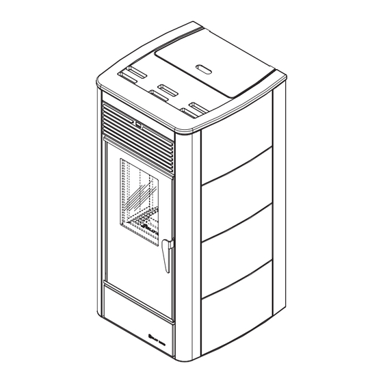
10 kW
15 kW
Air-pellet
STOVE
INSTALLATION,
USAGE AND MAINTENANCE SHEET
To be kept by the purchaser
Electronic control unit M10-P
Automatic start up
Table of
Contents
Previous
Page
Next
Page
1
2
3
4
5
Advertisement
Table of Contents
Need help?
Do you have a question about the Classe and is the answer not in the manual?
Ask a question
Questions and answers
Related Manuals for Jolly Mec Classe
Indoor Fireplace jolly mec Arte Acciaio Installation, Use And Maintenance Manual
18 kw and 23 kw heating stove (48 pages)
Pellet stove Jolly Mec Arte Installation, Use And Care Manual
(48 pages)
Pellet stove Jolly MEC I-DEA Quadra Installation, Use And Maintenance Manual
I-dea series air and pellet stove (44 pages)
Pellet stove Jolly Mec I-DEA IDRO Installation, Use And Maintenance Manual
Pellet fired stove with boiler (52 pages)
Pellet stove JOLLY MEC STILE Installation, Use And Maintenance Manual
Air and pellet stove (44 pages)
This manual is also suitable for:
Arte
Techna
Arte acciaio
Table of Contents
Print
Rename the bookmark
Delete bookmark?
Delete from my manuals?
Login
Sign In
OR
Sign in with Facebook
Sign in with Google
Upload manual
Upload from disk
Upload from URL


Need help?
Do you have a question about the Classe and is the answer not in the manual?
Questions and answers