Sign In
Upload
Download
Table of Contents
Contents
Add to my manuals
Delete from my manuals
Share
URL of this page:
HTML Link:
Bookmark this page
Add
Manual will be automatically added to "My Manuals"
Print this page
×
Bookmark added
×
Added to my manuals
Manuals
Brands
Jolly Mec Manuals
Pellet stove
STILE
Installation, use and maintenance manual
Jolly Mec STILE Installation, Use And Maintenance Manual
Air and pellet stove
Hide thumbs
1
Table Of Contents
2
3
4
5
6
7
8
9
10
11
12
13
14
15
16
17
18
19
20
21
22
23
24
25
26
27
28
29
30
31
32
33
34
35
36
37
38
39
40
41
42
43
44
page
of
44
Go
/
44
Contents
Table of Contents
Troubleshooting
Bookmarks
Table of Contents
Chap.01 Reference Guide
Table of Contents
Warnings
Applied Standards
Symbology
Use and Storing of the Installation and Maintenance Manual
Chap.02 Accident Prevention / Safety Regulations
General Considerations
Safety Regulations for Routine Maintenance and Use
Safety Regulations for Extraordinary Maintenance and Installation
Equipment for Operators and Maintenance Personnel
Residual Risks
Chap.03 Handling and Transport
Receiving Goods
Lifting and Transport
Chap.04 Description
Stove Presentation
Product Identification
Chap.05 Technical Data
Homologation en 14785:2006
Pellet Quality
Components
DIMENSIONS (in MM)
Flue or Fume Exhaust System
Installation Room Ventilation
Chap.06 Positioning and Connections for the Installer
Setting up of External Air Intakes and Electric Current
Phases of Assembling/Disassembling Stove Cladding
Optionals
Electrical Connections
Electronic Control Unit
Eko Plus/Stile Stove Control Unit Electrical Wiring Diagram
Chap.07 Use and Maintenance for the User
Stove Operations
Opening the Combustion Chamber Door
Display Position
User Lcd Display
Ir Remote Control
Pellet Hopper Safety Thermostat with Manual Reset
Recommendations and Warnings
ROUTINE MAINTENANCE (Done by Customer)
Detachable Components for Stove Cleaning
SCHEDULED PREVENTIVE MAINTENANCE (to be Done by a Specialised Technical Service Center)
Chap.08 Fault Diagnosis and Troubleshooting
Chap.09 Ecological Regulations
Waste Materials and Their Disposal
Disposal of the Machine
Advertisement
Quick Links
1
Stove Operations
2
Detachable Components for Stove Cleaning
3
Chap.08 Fault Diagnosis and Troubleshooting
Download this manual
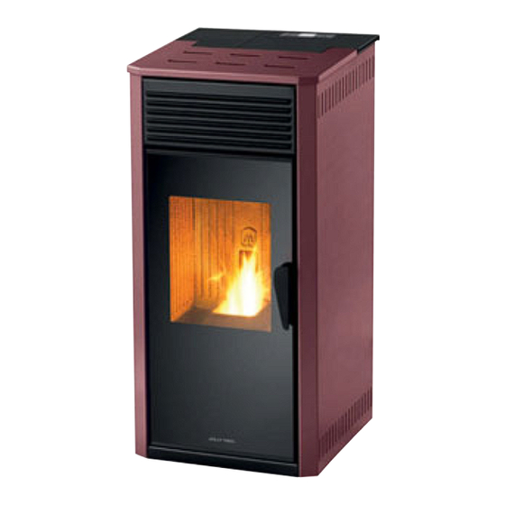
Air and
pellet STOVE
INSTALLATION, USE AND
MAINTENANCE MANUAL
To be kept by the purchaser
EKO Plus (6 kW)
STILE (8 kW)
Table of
Contents
Previous
Page
Next
Page
1
2
3
4
5
Advertisement
Table of Contents
Need help?
Do you have a question about the STILE and is the answer not in the manual?
Ask a question
Questions and answers
Related Manuals for Jolly Mec STILE
Pellet stove JOLLY MEC EKO Plus Installation, Use And Maintenance Manual
Air and pellet stove (44 pages)
Pellet stove Jolly MEC I-DEA Quadra Installation, Use And Maintenance Manual
I-dea series air and pellet stove (44 pages)
Pellet stove Jolly Mec Classe Installation, Use And Care Manual
(48 pages)
Pellet stove Jolly Mec I-DEA IDRO Installation, Use And Maintenance Manual
Pellet fired stove with boiler (52 pages)
This manual is also suitable for:
Eko plus
Table of Contents
Print
Rename the bookmark
Delete bookmark?
Delete from my manuals?
Login
Sign In
OR
Sign in with Facebook
Sign in with Google
Upload manual
Upload from disk
Upload from URL


Need help?
Do you have a question about the STILE and is the answer not in the manual?
Questions and answers