Table of Contents
Advertisement
Quick Links
PIT FIRE SERIES
INSTALLATION & OPERATING MANUAL
The Real Flame Pit Fire series are suitable to be installed into a masonry or
fireproof base, in outdoor installations only. Designed to operate on Natural
or LPG gases only. Approval no.GMK10130
Installed primarily as a decorative appliance. Not certified as a Space Heater.
VERSION 10
Advertisement
Table of Contents

Related Manuals for Real Flame PIT FIRE SERIES


Summary of Contents for Real Flame PIT FIRE SERIES
- Page 1 PIT FIRE SERIES INSTALLATION & OPERATING MANUAL The Real Flame Pit Fire series are suitable to be installed into a masonry or fireproof base, in outdoor installations only. Designed to operate on Natural or LPG gases only. Approval no.GMK10130 Installed primarily as a decorative appliance. Not certified as a Space Heater.
-
Page 2: Warranty Information
(www.realflame.com.au) or completing and mailing the attached registration card within 30 days of purchase of your Real Flame Gas Burner (or, if the Real Flame Gas Burner is fitted to a new home, within 30 days of the date of settlement of purchase of such new home). - Page 3 INSTALLATION NOTICE The installation of this appliance is only to be carried out by an authorised person in accordance with the Manufacturers Instructions, local gas fitting regulations, AS/NZS5601.1-2013 installation code for gas burning appliances and any other relevant statutory regulations. In all cases the installation of this appliance shall meet the requirements as set out in AS/NZS5601.1-2013.
-
Page 4: Table Of Contents
CONTENTS Contents ........................4 Dataplate ........................5 Dimensions ......................6 Installation instructions ....................7 Wiring Diagrams.....................14 Commissioning procedure ..................16 Media Installation ....................17 Operation - User Instructions.................20 Troubleshooting .....................20 Conversion details ....................21 Parts List ........................22 Real Flame contact information ................24... -
Page 5: Dataplate
DATA PLATE (Affixed to the gas valve controller cover of the appliance.) OFRD500 Injector Size (mm) N.G.C. (Mj/Hr) Natural Gas 3.30mm 0.90kPa 1.75mm 2.60kPa OFRD700 Injector Size (mm) N.G.C. (Mj/Hr) Natural Gas 4.0mm 0.95kPa 2.40mm 2.60kPa OFRT600x400 Injector Size (mm) N.G.C. -
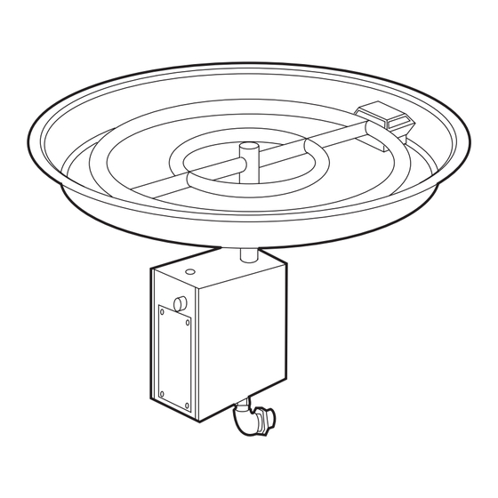
Page 6: Dimensions
DIMENSIONS MODEL FLANGE DIM FLANGE DIAMETER HEIGHT 560mm OFRD500 760mm OFRD700 OFRT600 X 400 OFRT800 X 400 OFSQ450 OFSQ600 Length Diameter Width 24.3 Height 61.5 Height Length Width 29.8 62.0 Height... -
Page 7: Installation Instructions
INSTALLATION INSTRUCTIONS Location Select a location where the outdoor fire can be supervised during operation. The outdoor fire is suitable for outdoor use only and must not be used indoors. An isolation switch must be fitted at the appliance or on an adjacent wall to allow for emergency shutdown and maintenance. - Page 8 30% or more in total of the remaining wall INSTALLATION INSTRUCTIONS (continued) area is open and unrestricted Both ends open Open side at least Example 3 Example 4 25% of total wall area 30% or more in total of the remaining wall area is open and unrestricted Open side at least...
- Page 9 INSTALLATION INSTRUCTIONS (continued) Optional Ignition Methods For 240 volt and 24 volt options, an electrical isolation switch must be fitted at the appliance or on an adjacent wall to allow for emergency shutdown and maintenance. An on/ off burner switch is located on the front face of the control box below the burner. An auxiliary switch can be located as follows –...
- Page 10 INSTALLATION INSTRUCTIONS (continued) Examples of enclosures Power Isolation Switch on nearby wall Minimum 750mm Drainage hose Isolation valve to garden Power Isolation Switch on nearby wall Minimum 750mm Vents x 2 Isolation valve Access panel 300x400 Drainage hose to garden...
- Page 11 INSTALLATION INSTRUCTIONS (continued) Optional Glass Surrounds Note: When installing the optional glass surrounds to your pit fire, use the B and C dimensions for centre to centre measurements for 5mm pilot hole. MODEL OFSQ450 OFSQ600 OFRT600 X 400 OFRT800 X 400 Diam 577 Diam 620 OFRD500...
- Page 12 INSTALLATION INSTRUCTIONS (continued) Examples of enclosures Glass surround If the finished burner height is lower than 750mm from ground level, an optional glass surround must be ordered and fixed Power Isolation with the fixing 750mm Switch on nearby wall brackets supplied. Available glass heights are 200mm and 400mm...
- Page 13 INSTALLATION INSTRUCTIONS (continued) APPLIANCES INCORPORATING INTEGRAL LPG SUPPLY SYSTEMS Cylinder retention Lateral movement shall not exceed 25mm at the retention means. Any movement shall not transmit strain to rigid tubing or pipe connections. ENCLOSURES FOR INTEGRAL LPG SUPPLY SYSTEMS Ventilation of cylinder enclosure Ventilation openings shall: be provided at high and low levels;...
- Page 14 INSTALLATION INSTRUCTIONS (continued) Construction of Enclosure (continued) TYPICAL MASONRY / BRICKWORK SURROUND Enclosure constructed from non-combustible materials Ventilation 750mm min enclosure height Ventilation 150mm Access door 300 x 400mm min TYPICAL FIXED TABLE / FABRICATED ENCLOSURE Glass or similar fixed barrier 20mm air gap under glass or similar fixed barrier Table or similar enclosure...
- Page 15 INSTALLATION INSTRUCTIONS (continued) • Note appliance gas type – Natural gas or ULPG. Should the appliance be the incorrect gas type please contact the supplier. • Gas isolation valve is to be accessible and located outside the enclosure. • Ensure wiring to the appliance is protected and not creating a hazard. •...
-
Page 16: Wiring Diagrams
WIRING DIAGRAMS Optional 240v Directly wired CNE DIRECT SPARK IGNITION MODULE Blue CCA-0835 3333L1012 Spark Spark S GND V Flame sensing Brown Green/Yellow Green/Yellow Green/ Valve Green/Yellow Black Blue Yellow Brown Black Isolation switch On/Off switch Transformer 240/24V Black Orange Orange 240V On/Off Switch 24V... -
Page 17: Commissioning Procedure
COMMISSIONING PROCEDURE (prior to installing media) Once the outdoor fire is installed. • Check for gas leaks. • Carry out the lighting procedure. • Check burner pressures and adjust as per Dataplate. • Turn appliance off. • Install media as per media installation instructions. •... - Page 18 MEDIA INSTALLATION (continued) Glass media Fill tray with volcanic rock the rock level reaches the bottom of the burner tubes. Lay glass media on top of volcanic rock until burner tubes are covered by one layer of glass media. Spread evenly around tray. Do not cover pilot area.
- Page 19 MEDIA INSTALLATION (continued) Volcanic Rock with ceramic logs Appliance must be fitted with Ceramic log kit. Fill tray with volcanic rock as per above instructions. Do not cover pilot area. Do not overfill with rock above the pilot cover level. Place logs on top of volcanic rock in a random stacking arrangement.
-
Page 20: Operation - User Instructions
OPERATION – USER INSTRUCTIONS Do not operate if you smell gas. Turn appliance off, extinguish any open flame. Contact your installer or a licensed gasfitter. When fire is not in use turn off gas and power to appliance. Fire must be covered when not in use. Do not use if any part of this appliance has been submerged in water. -
Page 21: Conversion Details
CONVERSION DETAILS Natural gas to propane. Turn appliance off. Turn gas supply off. Disconnect gas from valve inlet connection. Remove fire assembly from enclosure. Unscrew pilot assembly from valve. Remove ignition wires from pilot. Unscrew valve assembly from burner and tray. Unscrew and remove aeration - injector fitting. -
Page 22: Parts List
PARTS LIST Valve SIT Pilot assembly Natural gas SIT Pilot assembly Propane Injector Natural gas Injector ULPG Gas controller CNE CCA-0835... - Page 23 CHEMINEE PTY LTD EMAIL sales@cheminee.com.au WEBSITE www.Cheminee.com.au PHONE 02 9564 2694 FAX 02 9569 8802 SHOWROOM 118 Stanmore Road, Stanmore (Corner Wemyss St) NSW...
Need help?
Do you have a question about the PIT FIRE SERIES and is the answer not in the manual?
Questions and answers