Vacon 20 Complete User's Manual
Ac drives
Hide thumbs
Also See for 20:
- Complete user's manual (156 pages) ,
- Quick manual (62 pages) ,
- User manual (28 pages)
Table of Contents
Advertisement
Advertisement
Table of Contents

Subscribe to Our Youtube Channel
Related Manuals for Vacon 20


Summary of Contents for Vacon 20
- Page 1 ® ac drives complete user manual...
-
Page 3: Table Of Contents
3.2.6General cabling rules 3.2.7Stripping lengths of motor and mains cables 3.2.8Cable installation and the UL standards 3.2.9Cable and motor insulation checks 4.Commissioning 4.1Commissioning steps of Vacon 20 5.Fault tracing 6.Vacon 20 Application Interface 6.1Introduction 6.2Control I / O 7.Control panel 7.1General... - Page 4 7.4Navigation on the Vacon 20 control panel 7.4.1Main menu 7.4.2Reference menu 7.4.3Monitoring menu 7.4.4Parameter menu 7.4.5System menu 8.STANDARD application parameters 8.1Quick setup parameters (Virtual menu, shows when par. 17.2 = 1) 72 8.2Motor settings (Control panel: Menu PAR -> P1) 8.3Start / stop setup (Control panel: Menu PAR ->...
- Page 5 9.17.3Modbus process data 10.Technical data 10.1Vacon 20 technical data 10.2Power ratings 10.2.1Vacon 20 – Mains voltage 208-240 V 10.2.2Vacon 20 – Mains voltage 115 V 10.2.3Vacon 20 – Mains voltage 380-480 V 10.2.4Vacon 20 – Mains voltage 600 V 10.3Brake resistors...
-
Page 7: Safety
The motor terminals U, V, W (T1, T2, T3) and the possible brake resistor terminals - / + are live when Vacon 20 is connected to mains, even if the motor is not running. The control I / O-terminals are isolated from the mains poten- tial. - Page 8 After disconnecting the frequency converter from the mains, wait until the fan stops and the indicators on the display go out. Wait 5 more minutes before doing any work on Vacon 20 connections. The motor can start automatically after a fault situation, if the...
-
Page 9: Safety Instructions
Do not open the cover of Vacon 20. Static voltage discharge from your fingers may damage the components. Opening the cover may also damage the device. If the cover of Vacon 20 is opened, warranty becomes void. 1.3 Earthing and earth fault protection The Vacon 20 frequency converter must always be earthed with an earthing conduc- tor connected to the earthing terminal. - Page 10 • vacon safety • The earth fault protection inside the frequency converter protects only the converter itself against earth faults. • If fault current protective switches are used they must be tested with the drive with earth fault currents that are possible to arise in...
-
Page 11: Before Running The Motor
• safety vacon 1.4 Before running the motor Checklist: Before starting the motor, check that the motor is mounted properly and ensure that the machine connected to the motor allows the motor to be started. Set the maximum motor speed (frequency) according to the motor and the machine connected to it. - Page 12 • vacon safety...
-
Page 13: Receipt Of Delivery
+DLUS = US English +DLIT = Italian empty = English Figure 2.1: Vacon 20 type designation code 2.2 Storage If the frequency converter is to be kept in store before use make sure that the ambi- ent conditions are acceptable: Storing temperature -40…+70 °C... -
Page 14: Maintenance
2.3 Maintenance In normal operating conditions, Vacon 20 frequency converters are maintenance- free. However, regular maintenance is recommended to ensure a trouble-free oper- ating and a long lifetime of the drive. We recommended to follow the table below for maintenance intervals. -
Page 15: Warranty
The local distributor may grant a warranty time different from the above. This war- ranty time shall be specified in the distributor's sales and warranty terms. Vacon as- sumes no responsibility for any other warranties than that granted by Vacon itself. -
Page 16: Manufacturer's Declaration Of Conformity
Product name: Vacon 20 Frequency Converter Model designation: Vacon 20 1L 0001 2…to 0009 2 Vacon 20 3L 0001 2…to 0038 2 Vacon 20 3L 0001 4…to 0038 4 has been designed and manufactured in accordance with the following... -
Page 17: Installation
• installation vacon 3. INSTALLATION 3.1 Mechanical installation There are two possible ways to mount Vacon 20 in the wall. For MI1-MI3, either screw or DIN-rail mounting; For MI4-MI5, screw or flange mounting. BACK BACK RESET RESET BACK RESET Figure 3.1: Screw mounting, MI1 - MI3... - Page 18 • vacon installation Figure 3.3: DIN-rail mounting, MI1 - MI3 BACK RESET Figure 3.4: Flange mounting, MI4 - MI5...
- Page 19 • installation vacon Figure 3.5: Flange mounting cutout dimensions for MI4 (Unit: mm) Figure 3.6: Flange mounting cutout dimensions for MI5 (Unit: mm)
- Page 20 • vacon installation Figure 3.7: Flange mounting depth dimensions for MI4 and MI5 (Unit: mm)
-
Page 21: 1Vacon 20 Dimensions
• installation vacon 3.1.1 Vacon 20 dimensions D (D1) W (W1) Figure 3.8: Vacon 20 dimensions, MI1 - MI3 D (D1) W (W1) Figure 3.9: Vacon 20 dimensions, MI4 - MI5... - Page 22 336.5 Table 3.1: Vacon 20 dimensions in millimetres Frame Dimensions(mm) Weight* (kg.) 254.3 *without shipping package Table 3.2: Vacon 20 frame dimensions (mm) and weights (kg) Frame Dimensions(Inches) Weight* (Ibs.) 14.6 16.3 *without shipping package Table 3.3: Vacon 20 frame dimensions (Inch) and weights (Ibs)
- Page 23 • installation vacon Figure 3.10: Vacon20 dimensions, MI2 - 3 Display Location Frame Dimensions (mm) 22.3...
- Page 24 • vacon installation Figure 3.11: Vacon20 dimensions, MI4 - 5 Display Location Dimensions Frame (mm) 248.5...
-
Page 25: 2Cooling
NOTE! See the mounting dimensions on the back of the drive. Leave free space for cooling above (100 mm), below (50 mm), and on the sides (20 mm) of Vacon 20! (For MI1 - MI3, side-to-side installation allowed only if the ambient tem- perature is below 40 °C;... -
Page 26: 3Power Losses
• vacon installation 3.1.3 Power losses If the operator wants to raise the switching frequency of the drive for some reason (typically e.g. in order to reduce the motor noise), this inevitably affects the power losses and cooling requirements, for different motor shaft power, operator can se- lect the switching frequency according to the graphs below. - Page 27 • installation vacon...
- Page 28 • vacon installation MI1 - MI5 3P 230 V POWER LOSS...
- Page 29 • installation vacon...
- Page 30 • vacon installation...
- Page 31 • installation vacon MI1 - MI3 1P 230 V POWER LOSS...
- Page 32 • vacon installation...
-
Page 33: 4Emc Levels
• installation vacon 3.1.4 EMC levels EN61800-3 defines the division of frequency converters into four classes according to the level of electromagnetic disturbances emitted, the requirements of a power system network and the installation environment (see below). The EMC class of each product is defined in the type designation code. -
Page 34: 5Changing The Emc Protection Class From C2 Or C3 To C4
• vacon installation 3.1.5 Changing the EMC protection class from C2 or C3 to C4 The EMC protection class of MI1-3 frequency converters can be changed from class C2 or C3 to class C4 by removing the EMC-capacitor disconnecting screw, see fig- ure below. - Page 35 • installation vacon Figure 3.15: EMC protection class, MI5 Figure 3.16: Jumpers • Remove the main cover and locate the two jumpers. • Disconnect the RFI-filters from ground by lifting the jumpers up from their default positions. See Figure 3.11...
-
Page 36: Cabling And Connections
3 ~(230V, 400V, 600V) 3~(230V, 400V, 600V) 1~ (230V) 1~ (115V) Motor out L1 L2/N L3 R+ R- U/T1 V/T2 W/T3 Strip the plastic cable coating for 360° earthing BRAKE MOTOR MAINS RESISTOR Figure 3.18: Vacon 20 power connections, MI2 - MI3... - Page 37 • installation vacon 3~ (380, 480V) Motor out Brake RESISTOR MOTOR MAINS Figure 3.19: Vacon 20 power connections, MI4 3~ (380, 480V) Motor out Brake MAINS MOTOR RESISTOR Figure 3.20: Vacon 20 power connections, MI5...
-
Page 38: 2Control Cabling
• vacon installation 3.2.2 Control cabling Attach the support AFTER installing the power cables Attach this plate BEFORE installing the power cables Figure 3.21: Mount the PE-plate and API cable support, MI1 - MI3... - Page 39 • installation vacon Attach the support AFTER installing Attach this plate BEFORE installing the power cables Figure 3.22: Mount the PE-plate and API cable support, MI4 - MI5...
- Page 40 • vacon installation Figure 3.23: Open the lid, MI1 - MI3 Figure 3.24: Open the lid, MI4 - MI5...
- Page 41 • installation vacon Control cable tightening torque: 0.4 Nm Strip the plastic cable coating for 360°earthing Figure 3.25: Install the control cables. MI1 - MI3. See Chapter 6.2 Figure 3.26: Install the control cables. MI4 - MI5. See Chapter 6.2...
-
Page 42: 3Allowed Option Boards In Vacon20
• vacon installation 3.2.3 Allowed option boards in Vacon20 See below for the allowed option boards in the slot: Note! OPT-B1 and OPT-B4 only support external power supply. Option board assembly structure:... - Page 43 • installation vacon...
-
Page 44: 4Screw Of Cables
• vacon installation 3.2.4 Screw of cables M4*8 Screws 12pcs Figure 3.27: MI1 screws M4*8 Screws 10pcs Figure 3.28: MI2 screws... - Page 45 • installation vacon M4*8 Screws 10pcs M4*10 Screws 4pcs Figure 3.29: MI3 screws M4*9 Screws 14pcs M4*17 Screws 6pcs Figure 3.30: MI4 - MI5 screw...
-
Page 46: 5Cable And Fuse Specifications
• vacon installation 3.2.5 Cable and fuse specifications Use cables with heat resistance of at least +70 °C. The cables and the fuses must be dimensioned according to the tables below. Installation of cables according to UL regulations is presented in Chapter 3.2.8. - Page 47 3*1.5+1.5 1.5-4 1.5-4 0.5-1.5 0.5-1.5 0009 2*6+6 3*1.5+1.5 1.5-6 1.5-6 0.5-1.5 0.5-1.5 Table 3.9: Cable and fuse sizes for Vacon 20, 208 - 240 V, 1~ Terminal cable size (min/max) Mains Motor Fuse cable cable Frame Type Main Earth Control...
- Page 48 1-10 0.5-1.5 0.5-1.5 2.5-50 0031-0038 3*10+10 3*10+10 2.5-35 0.5-1.5 0.5-1.5 Cu / Al Table 3.11: Cable and fuse sizes for Vacon 20, 380 - 480 V, 3~ Terminal cable size (min/max) Mains Motor cable Fuse cable Frame Type Main Earth...
-
Page 49: 6General Cabling Rules
• installation vacon 3.2.6 General cabling rules Before starting the installation, check that none of the components of the fre- quency converter is live. Place the motor cables sufficiently far from other cables: • Avoid placing the motor cables in long parallel lines with other cables. -
Page 50: 7Stripping Lengths Of Motor And Mains Cables
3.2.7 Stripping lengths of motor and mains cables Earth con ductor 8 mm 8 mm 20 mm 35 mm Figure 3.31: Stripping of cables Note! Strip also the plastic cover of the cables for 360 degree earthing. See Figures 3.17, 3.18 and 3.25. - Page 51 • installation vacon between each phase conductor as well as between each phase conductor and the protective ground conductor. The insulation resistance must be >1 MOhm. 2. Mains cable insulation checks Disconnect the mains cable from terminals L1, L2 / N and L3 of the frequency con- verter and from the mains.
- Page 52 • vacon installation...
-
Page 53: Commissioning
4. COMMISSIONING Before commissioning, read the warnings and instructions listed in Chapter 1! 4.1 Commissioning steps of Vacon 20 Read carefully the safety instructions in Chapter 1 and follow them. After the installation, make sure that: • both the frequency converter and the motor are grounded. - Page 54 • vacon commissioning Perform test run without motor. Perform either Test A or Test B: A) Control from the I / O terminals: • Turn the Start/Stop switch to ON position. • Change the frequency reference (potentiometer). • Check the Monitoring Menu and make sure that the value of Output fre- quency changes according to the change of frequency reference.
-
Page 55: Fault Tracing
• fault tracing vacon 5. FAULT TRACING When a fatal fault is detected by the frequency converter control electronics, the drive will stop and the symbol FT and the fault code blinked on the display are in the following format, e.g.:... - Page 56 • vacon fault tracing Fault Fault name Possible cause Correcting actions code Reset the fault and restart. If the fault re-occurs, con- tact the distributor near to • component failure System fault you. • faulty operation NOTE! If fault F8 occurs,...
- Page 57 < 2 V. Check the current loop signal range 4 to • control cable is broken or circuitry. 20 mA or 2 to 10 V) loose. • signal source has failed. Digital input fault. Digital input has been programmed as exter-...
- Page 58 Vacon distributor. Check installation. The data connection between the If installation is correct, Fieldbus fault fieldbus Master and the fieldbus contact the nearest Vacon of the drive has broken. distributor. Check board and slot. The connection between optional Slot fault Contact the nearest Vacon board and API has been broken.
-
Page 59: Vacon 20 Application Interface
RS-485 Interface Table 6.1: Available Control Board This section provides you with a description of the I / O-signals for Vacon 20 and in- structions for using the Vacon 20 general purpose application. The frequency reference can be selected from Preset Speed 0, Keypad, Fieldbus, AI1, AI2, AI1+AI2, PID, Motor potentiometer and Pulse train / Encoder. - Page 60 • vacon vacon 20 api • Protections and supervisions (all fully programmable; off, alarm, fault): • Analog input low fault • External fault • Undervoltage fault • Earth fault • Motor thermal, stall and underload protection • Fieldbus communication • Output phase fault •...
-
Page 61: Control I / O
20 DO Digital signal out Active = READY 50 mA Table 6.2: Vacon 20 General purpose application default I / O configuration and connections for control board P) = Programmable function, see parameter lists and descriptions, chapters 8 and 9. - Page 62 25 RO 21 Active = FAULT 250 Vac / 3 A 26 RO 24 Table 6.2: Vacon 20 General purpose application default I / O configuration and connections for control board P) = Programmable function, see parameter lists and descriptions, chapters 8 and 9.
-
Page 63: Control Panel
• control panel vacon 7. CONTROL PANEL 7.1 General The panel is an irremovable part of the drive consisting of corresponding control board; The overlay with display status on the cover and the button are in clarifica- tions in the user language. -
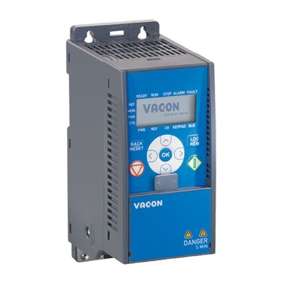
Page 64: Keypad
FAULT KEYPAD BACK RESET Figure 7.1: Vacon 20 Control panel 7.3 Keypad The keypad section of the control panel consists of 9 buttons (see Figure 7.1). The buttons and their functions are described as Table 7.1. The drive stops by pressing the keypad STOP button, regardless of the selected con- trol place when Par. - Page 65 • control panel vacon Symbol Button Name Function Description Start Motor START from the panel STOP Motor STOP from the panel Used for confirmation.Enter edit mode for parameter. Alternate in display between the parameter value and parameter code. Reference frequency value adjusting no need to press OK-button to confirm.
-
Page 66: Navigation On The Vacon 20 Control Panel
This chapter provides you with information on navigating the menus on Vacon 20 and editing the values of the parameters. 7.4.1 Main menu The menu structure of Vacon 20 control software consists of a main menu and sev- eral submenus. Navigation in the main menu is shown below: R E A D Y... -
Page 67: 2Reference Menu
• control panel vacon 7.4.2 Reference menu RE ADY R UN S TOP ALAR M FAULT RE F M O N PA R F WD KEY PAD B US Press to enter Change edit mode value Figure 7.3: Reference menu display Move to the reference menu with the UP / DOWN button (see Figure 7.2). -
Page 68: 3Monitoring Menu
Figure 7.4: Monitoring menu display Monitoring values are actual values of measured signals as well as status of some control settings. It is visible in Vacon 20 display, but it can not be edited. The moni- toring values are listed in Table 7.2. - Page 69 • control panel vacon Code Monitoring signal Unit Description V1.1 Output frequency Output frequency to motor Frequency reference to motor con- V1.2 Frequency reference trol V1.3 Motor speed Calculated motor speed V1.4 Motor current Measured motor current Calculated actual / nominal torque V1.5...
- Page 70 Kelvins) by parameter set- ting, hidden until an option board is connected Measured value of Temperature input 3 in temperature unit (Cel- V2.20 Temperature input 3 sius or Kelvins) by parameter set- ting, hidden until an option board is connected...
- Page 71 • control panel vacon Code Monitoring signal Unit Description Bit codes status of application: B3 = Ramp 2 Active B5 = Remote CTRL Place 1 active B6 = Remote CTRL Place 2 active V3.2 Application status word B7 = Fieldbus Control Active...
-
Page 72: 4Parameter Menu
• vacon control panel 7.4.4 Parameter menu In Parameter menu only the Quick setup parameter list is shown as default. By giving the value 0 to the parameter 17.2, it is possible to open other advanced parameter groups. The parameter lists and descriptions can be found in chapters 8 and 9. - Page 73 • control panel vacon In edit mode, Left and Right buttons are used to select the digit which has to be changed, and Up increases / Down decreases parameter value. In edit mode, the value of Px.x is displayed blinkingly in the panel. After about 10 s, Px.x is displayed in the panel again if you don't press any button.
-
Page 74: 5System Menu
• vacon control panel 7.4.5 System menu SYS menu including fault submenu, field bus submenu and system parameter sub- menu, and the display and operation of the system parameter submenu is similar to PAR menu or MON menu.In system parameter submenu, there are some editable parameter (P) and some uneditable parameter (V). - Page 75 • control panel vacon Note! Fault History can be reset by long pressing the BACK / RESET button for 5 second time,when the API is in fault history sub- menu level (F6.x), it will also clear all active faults. See Chapter 5 for fault descriptions.
- Page 76 • vacon control panel...
-
Page 77: Standard Application Parameters
Modifiable only in stop state NOTE: This manual is for Vacon 20 standard application only. If you need more ap- plication information, please download the appropriate user manual on http:// www.vacon.com -> Support & Downloads. -
Page 78: Quick Setup Parameters (Virtual Menu, Shows When Par. 17.2 = 1)
• vacon parameters 8.1 Quick setup parameters (Virtual menu, shows when par. 17.2 = 1) Code Parameter Unit Default Note Motor nominal Check rating plate on the Varies P1.1 motor. voltage Motor nominal 50,00 / Check rating plate on the 30,00 320,00 P1.2... - Page 79 0 Hz. 0 = 0 - 100% 1 = 20% - 100% P6.1 AI1 Signal range 20% is the same as 2 V minimum signal level. 0 = 0 - 100% 1 = 20% - 100% P6.5 AI2 Signal range...
-
Page 80: Motor Settings (Control Panel: Menu Par -> P1)
• vacon parameters 8.2 Motor settings (Control panel: Menu PAR -> P1) Code Parameter Unit Default Note Motor nominal Check rating plate on the Varies P1.1 voltage motor 50,00 / Motor nominal fre- Check rating plate on the 30,00 320,00 P1.2... - Page 81 0 = Not active Motor 1 = Standstill identification P1.19 identification (need run command within 20 s to activate) Voltage drop over motor windings as % of U Rs voltage drop 0,00 100,00 0,00 P1.20 nmot nominal current.
-
Page 82: Start / Stop Setup (Control Panel: Menu Par -> P2)
• vacon parameters Start / stop setup (Control panel: Menu PAR -> P2) Code Parameter Min Max Unit Default Note 0 = I / O terminals Remote Control P2.1 1 = Fieldbus Place Selection 2 = Keypad 0 = Ramp Start function P2.2... -
Page 83: Frequency References (Control Panel: Menu Par -> P3)
P3.6 Preset speed 2 P3.1 P3.2 15,00 106 Activated by digital inputs P3.7 Preset speed 3 P3.1 P3.2 20,00 126 Activated by digital inputs P3.8 Preset speed 4 P3.1 P3.2 25,00 127 Activated by digital inputs P3.9 Preset speed 5 P3.1... -
Page 84: Ramps And Brakes Setup (Control Panel: Menu Par -> P4)
• vacon parameters 8.5 Ramps and brakes setup (Control panel: Menu PAR -> P4) Code Parameter Unit Default Note 0 = Linear Ramp S-shape 1 10,0 P4.1 >0 = S-curve ramp time Defines the time required for the output Acceleration time 1... - Page 85 Decel2 Frequency P4.14 0,00 P3.2 0,00 528 0,00 = disabled Threshold Delay to open brake External Brake: P4.15 0,00 320,00 0,20 1544 after Open frequency Open Delay limit is reached External Brake: Opening frequency from P4.16 Open Frequency 0,00 P3.2 1,50...
-
Page 86: Digital Inputs (Control Panel: Menu Par -> P5)
• vacon parameters 8.6 Digital inputs (Control panel: Menu PAR -> P5) Code Parameter Max Unit Default ID Note 0 = Not used 1 = DI1 2 = DI2 3 = DI3 4 = DI4 5 = DI5 P5.1 I / O control signal 1... -
Page 87: Analogue Inputs (Control Panel: Menu Par -> P6)
Parameter Unit Default Note 0 = 0 - 100% (0 - 10 V) P6.1 AI1 Signal range 1 = 20% - 100% (2 - 10 V) P6.2 AI1 Custom min 100,00 0,00 380 0,00 = no min scaling -100,00 P6.3... -
Page 88: Digital Outputs (Control Panel: Menu Par -> P8)
15 = Analogue input superv. 16 = Preset Speed Active 17 = External Brake ctrl 18 = Keypad control active 19 = I / O control active 20 = Temperature supervision RO2 signal P8.2 Varies 314 As parameter 8.1 selcetion DO1 signal P8.3... - Page 89 • parameters vacon Code Parameter Unit Default Selections 0 = No inversion P8.4 RO2 inversion 1588 1 = Inverted P8.5 RO2 ON delay 0,00 320,00 0,00 460 0,00 = No delay P8.6 RO2 OFF delay 0,00 320,00 0,00 461 0,00 = No delay 0 = No inversion P8.7...
-
Page 90: Analogue Outputs (Control Panel: Menu Par -> P9)
• vacon parameters 8.10 Analogue outputs (Control panel: Menu PAR -> P9) Code Parameter Unit Default ID Selections 0 = Not used 1 = Output freq. (0-f 2 = Output current (0-I nMotor 3 = Motor torque (0-T nMotor 4 = PID output (0 - 100%) 5 = Freq. -
Page 91: Fieldbus Data-Mapping (Control Panel: Menu Par -> P10)
• parameters vacon Code Parameter Unit Default ID Selections As parameter P9.1, hidden Analog output E2 P9.9 until an option board is con- signal selection nected As parameter P9.2, hidden Analog output E2 P9.10 until an option board is con-... -
Page 92: Prohibited Frequencies (Control Panel: Menu Par -> P11)
• vacon parameters Code Parameter Unit Default Note FB Data Output 5 P10.5 Varies 856 Variable mapped on PD5 selection FB Data Output 6 P10.6 Varies 857 Variable mapped on PD6 selection FB Data Output 7 P10.7 Varies 858 Variable mapped on PD7... -
Page 93: Limit Supervisions (Control Panel: Menu Par -> P12)
• parameters vacon 8.13 Limit Supervisions (Control panel: Menu PAR -> P12) Code Parameter Unit Default Note Output freq. 0 = Not used P12.1 supervision func- 1 = Low limit tion 2 = High limit Output freq. Output frequency super- P12.2... -
Page 94: Protections (Control Panel: Menu Par -> P13)
• vacon parameters 8.14 Protections (Control panel: Menu PAR -> P13) Code Parameter Unit Default Note 0 = No action 1 = Alarm Analog Input low 2 = Alarm, preset alarm P13.1 fault frequency 3 = Fault: Stop function 4 = Fault: Coast... - Page 95 • parameters vacon Code Parameter Unit Default Note This is the maximum UL:Time limit 300,0 20,0 time allowed for an P13.16 underload state to exist Delay time for analog Analog Input low P13.17 10,0 1430 input low fault fault delay External fault 701 Same as parameter 13.3...
-
Page 96: Fault Autoreset Parameters (Control Panel: Menu Par -> P14)
• vacon parameters 8.15 Fault autoreset parameters (Control panel: Menu PAR -> P14) Code Parameter Unit Default ID Note 0 = Disabled Automatic Reset P14.1 1 = Enable Wait time 0,10 10,00 0,50 717 Waiting time after fault P14.2 Trial time... - Page 97 • parameters vacon Code Parameter Unit Default Note 0 = AI1 1 = AI2 2 = ProcessDataIn1 (0 -100%) 3 = ProcessDataIn2 (0 -100%) 4 = ProcessDataIn3 Feedback (0 -100%) P15.4 Varies source selection 5 = ProcessDataIn4 (0 -100%) 6 = AI2-AI1...
- Page 98 1035 Decimals on display decimal digits Process unit P15.20 P15,21 1033 Process min value minimum value Process unit P15.21 P15.20 3200,0 100,0 1034 Process max value maximum value Temperature min value for Temperature -50,0/ PID and frequency refer- P15.22 P15.23...
-
Page 99: Motor Pre-Heat (Control Panel: Menu Par -> P16)
• parameters vacon 8.17 Motor Pre-heat (Control panel: Menu PAR -> P16) Code Parameter Unit Default Note 0 = Not used Motor Pre-heat 1 = Always in stop state P16.1 1225 Function 2 = Controlled by digital input DC current for Pre-heat-... -
Page 100: System Parameters
• vacon parameters 8.19 System parameters Code Parameter Min Max Default Note Software information (MENU PAR -> V1) V1.1 API SW ID 2314 V1.2 API SW version V1.3 Power SW ID 2315 V1.4 Power SW version V1.5 Application ID V1.6 Application revision V1.7... - Page 101 0 = Non-existent or no bus power. 1 = Configuring state 2 = Established 3 = Timeout P2.2 Output assembly type 14012 20, 21, 23, 25, 101, 111 P2.3 MAC ID 14010 1 = 125 kbit/s P2.4 Baud rate 14011...
- Page 102 • vacon parameters Code Parameter Min Max Default Note When ProfidBus E3/E5 board has been installed, the comm. Parameters are as follows V2.1 Communication status 14022 V2.2 Fieldbus protocol status 14023 V2.3 Active protocol 14024 V2.4 Active buad rate 14025 V2.5...
- Page 103 • parameters vacon Code Parameter Min Max Default Note Other information V3.1 MWh counter Million Watt Hour V3.2 Power on days V3.3 Power on hours V3.4 Run counter: Days V3.5 Run counter: Hours V3.6 Fault counter Panel parameter set Hidden when connect V3.7...
- Page 104 • vacon parameters...
-
Page 105: Parameter Descriptions
• parameter descriptions vacon 9. PARAMETER DESCRIPTIONS On the next pages you can find the descriptions of certain parameters. The descrip- tions have been arranged according to parameter group and number. 9.1 Motor settings (Control panel: Menu PAR -> P1) - Page 106 • vacon parameter descriptions 1 = Square: The voltage of the motor changes following a squared curve form with the frequency in the area from 0 Hz to the field weakening point where the field weakening point voltage is also supplied to the motor. The motor runs under magnetised below the field weakening point and produces less torque, power losses and electromechanical noise.
- Page 107 • parameter descriptions vacon U [V ] P a r. 1.11 D efau lt: N om inal F ield w ea kening voltage of the m otor po int P a r. 1 .1 3 D efault: N om ina l...
- Page 108 WITCHING FREQUENCY Motor noise can be minimised using a high switching frequency. Increasing the switching frequency reduces the capacity of the frequency converter unit. Switching frequency for Vacon 20: 1.5…16 kHz. 1.17 B RAKE CHOPPER Note! An internal brake chopper is installed in three phase supply MI2 and MI3 size drives.
- Page 109 When Standstill identification is selected, the drive will perform an ID-run when it is started from selected control place. Drive has to be started within 20 seconds, otherwise identification is aborted. The drive does not rotate the motor during Standstill identification. When ID run is ready the drive is stopped.
-
Page 110: Start / Stop Setup (Control Panel: Menu Par -> P2)
Local = Keyp ad is the control place Remote = Control place determined by P2.1 TART FUNCTION The user can select two start functions for Vacon 20 with this parameter: 0 = Ramp start The frequency converter starts from 0 Hz and accelerates to the set frequency reference within the set acceleration time (See detailed de- scription: ID103). - Page 111 • parameter descriptions vacon After the Stop command, the speed of the motor is decelerated ac- cording to the set deceleration parameters. If the regenerated energy is high it may be necessary to use an exter- nal braking resistor for to be able to decelerate the motor in accepta- ble time.
- Page 112 • vacon parameter descriptions Explanations Control signal (CS) 1 actives causing the Run enable signal is set to FALSE, which output frequency to rise. The motor runs drops the frequency to 0.The run enable forward. signal is configured with par. 5.7.
- Page 113 • parameter descriptions vacon Selection Selection name Note number CS1:Forward(edge) CS2:Inverted stop Output frequerty frequerty 0 Hz frequerty Run enable Ctrl signal 1 Ctrl signal 2 Keypad stop button Figure 9.4: Start/Stop logic, selection 1 Explanations Control signal (CS) 1 actives causing the CS1 activates and the motor accelerates output frequency to rise.
- Page 114 • vacon parameter descriptions Selection Selection name Note number Shall be used to exclude the possibility of an CS1:Forward(edge) unintentional start. The Start / Stop contact must CS2:Backward(edge) be opened before the motor can be restarted. Output frequerty frequerty 0 Hz...
- Page 115 • parameter descriptions vacon Selection Selection name Note number CS1:Start CS2:Reverse Output frequerty frequerty 0 Hz frequerty Run enable Ctrl signal 1 Ctrl signal 2 Keypad start button Keypad stop button Figure 9.6: Start/Stop logic, selection 3 Explanations: Control signal (CS) 1 actives causing the Run enable signal is set to FALSE, which output frequency to rise.
- Page 116 • vacon parameter descriptions Selection Selection name Note number Shall be used to exclude the possibility of an unin- CS1:Start(edge) tentional start. The Start / Stop contact must be CS2:Reverse opened before the motor can be restarted. Output frequerty frequerty...
- Page 117 FieldBus) or local. 0 = Remote Control 1 = Local Control The priority order of selecting control place is 1. PC control from Vacon live operation window 2. Loc / Rem button 3. Forced from I / O terminal...
-
Page 118: Frequency References (Control Panel: Menu Par -> P3)
• vacon parameter descriptions 9.3 Frequency references (Control panel: Menu PAR -> P3) EMOTE CONTROL PLACE FREQUENCY REFERENCE SELECTION It defines the selected frequency reference source when the drive is remote control. A second reference source is programmable in par. 3.12. - Page 119 • parameter descriptions vacon 3.13 M OTOR POTENTIOMETER RAMP 3.14 M OTOR POTENTIOMETER RESET P3.13 is the speed variation ramp when motor potentiometer reference is in- creased or decreased. P3.14 tells under which circumstances the potentiometers reference should be reset and start over from 0 Hz.
-
Page 120: Ramps & Brakes Setup (Control Panel: Menu Par -> P4)
• vacon parameter descriptions 9.4 Ramps & brakes setup (Control panel: Menu PAR -> P4) SHAPE The start and end of the acceleration and deceleration ramp can be smoothed with this parameter. Setting value 0 gives a linear ramp shape which causes acceleration and deceleration to act immediately to the changes in the refer- ence signal. - Page 121 • parameter descriptions vacon LUX BRAKING Instead of DC braking, flux braking is a useful form of braking with motors of max. 15 kW. When braking is needed, the frequency is reduced and the flux in the motor is increased, which in turn increases the motor's capability to brake. Unlike DC braking, the motor speed remains controlled during braking.
- Page 122 • vacon parameter descriptions f out f out Output frequency Motor speed Output frequency Motor speed 0,1 x f n DC-braking ON DC-braking ON t = 0,1 x par. 4.10 t = 1 x par. 4.10 STOP STOP Figure 9.10: DC-braking time when Stop mode = Coasting Par.
- Page 123 • parameter descriptions vacon 4.11 S CURRENT FREQUENCY It is the output frequency at which the DC-braking is applied. 4.12 S TART CURRENT TIME DC-brake is activated when the start command is given. This parameter de fines the time for how long DC current is fed to motor before acceleration starts.
- Page 124 • vacon parameter descriptions 2. When the Opening frequency limit has been reached the Open delay (P4.15) must also elapse. Note! The output frequency is held at the Open frequency limit until this. 3. When the two previous conditions are reached. The brake will open if the output current is higher than the current limit.(P4.19)
-
Page 125: Digital Inputs (Control Panel: Menu Par -> P5)
• parameter descriptions vacon 9.5 Digital inputs (Control panel: Menu PAR -> P5) These parameters are programmed using the FTT-method (Function To Ter- minal), where you have a fixed input or output that you define a certain func- tion for. You can also define more than one function to a digital input, e.g. Start signal 1 and Preset Speed B1 to DI1. -
Page 126: Analogue Inputs (Control Panel: Menu Par -> P6)
• vacon parameter descriptions 9.6 Analogue inputs (Control panel: Menu PAR -> P6) FILTER TIME FILTER TIME This parameter, given a value greater than 0, activates the function that filters out disturbances from the incoming analogue signal. Long filtering time makes the regulation response slower. See Figure 9.14. -
Page 127: Pulse Train / Encoder (Control Panel: Menu Par -> P7)
• parameter descriptions vacon 9.7 Pulse train / Encoder (Control panel: Menu PAR -> P7) IN PULSE FREQUENCY AX PULSE FREQUENCY Minimum and maximum pulse frequency correspond to a signal value of 0% and 100% respectively. Frequencies over Max pulse frequency are handled as constant 100% and below Min pulse frequency as constant 0%. -
Page 128: Digital Outputs (Control Panel: Menu Par -> P8)
• vacon parameter descriptions 9.8 Digital outputs (Control panel: Menu PAR -> P8) SIGNAL SELECTION SIGNAL SELCETION SIGNAL SELCETION Setting Signal content 0 = Not used Output is not in operation. 1 = Ready The frequency converter is ready to operate. -
Page 129: Analogue Outputs (Control Panel: Menu Par -> P9)
• parameter descriptions vacon 9.9 Analogue outputs (Control panel: Menu PAR -> P9) NALOG OUTPUT SIGNAL SELECTION 0 = Not used 1 = Output frequency (0 - f 2 = Output current (0 - I nMotor 3 = Motor torque (0 - T... -
Page 130: Fieldbus Data-Mapping (Control Panel: Menu Par -> P10)
• vacon parameter descriptions 9.10 Fieldbus Data-Mapping (Control panel: Menu PAR -> P10) 10.1 FB DATA OUT SELECTION Parameter couples read only variables to output process data 1. 0 = Frequency reference 1 = Output reference 2 = Motor speed... -
Page 131: Prohibited Frequencies (Control Panel: Menu Par -> P11)
• parameter descriptions vacon 9.11 Prohibited Frequencies (Control panel: Menu PAR -> P11) 11.1 P 1: L ROHIBIT FREQUENCY RANGE OW LIMIT 11.2 P 1: H ROHIBIT FREQUENCY RANGE IGH LIMIT 11.3 P 2: L ROHIBIT FREQUENCY RANGE OW LIMIT 11.4 P... -
Page 132: Protections (Control Panel:menu Par->P13)
If other than nominal motor is used with the drive, the accuracy of the torque calculation decreases. The default parameter value of the underload protection time limit is 20 sec- onds, which is the maximum time allowed for an underload state to exist be-... - Page 133 • parameter descriptions vacon To rq ue U n derloa d cu rv e at Feild weakening point, P13.14(default)=50% U n derloa d curve at ze ro fre q. P13.15= 10% U nd e rlo ad a re a 5 H z Fi eld w ea ken in g po in t , P1 .11...
- Page 134 MBIENT TEMPERATURE When the motor ambient temperature must be taken into consideration, it is recommended to set a value for this parameter. The value can be set between -20 and 100 degrees Celsius. 13.9 M ERO SPEED COOLING Defines the cooling factor at zero speed in relation to the point where the mo- tor is running at nominal speed without external cooling.
- Page 135 • parameter descriptions vacon cooling Overload area 100% P13.9=40% Corner freq Figure 9.17: Motor thermal current IT curve 13.10 M THERMAL TIME CONSTANT This time can be set between 1 and 200 minutes. This is the thermal time constant of the motor. The bigger the frame and/or slower the speed of the motor, the longer the time constants.
- Page 136 • vacon parameter descriptions Motor temperature Trip area 105% Motor Fault/w arning current activation p o int, if selected w ith par. Time cons tantT *) Q = (I/I T ) 2 x (1-e -t/T ) Time Motor temperature Changes by motor size and adjusted with parameter .
- Page 137 This is the maximum time allowed for a stall stage. The stall time is counted by an internal up/down counter. If the stall time counter value goes above this limit the protection will cause a trip (see P13.5).See Figure 9.20. Stall time counter Trip area Par.13.12...
- Page 138 • vacon parameter descriptions This is the maximum time allowed for an underload state to exist. An internal up/down counter counts the accumulated underload time. If the underload counter value goes above this limit the protection will cause a trip according to parameter P13.6).
-
Page 139: Automatic Reset (Control Panel: Menu Par -> P14)
• parameter descriptions vacon 9.13 Automatic reset (Control panel: Menu PAR -> P14) 14.1 A UTOMATIC RESET Activate the Automatic reset after fault with this parameter. NOTE: Automatic reset is allowed for certain faults only. Fault: 1. Under voltage 2. Over voltage 3. -
Page 140: Pid Control Parameters (Control Panel: Menu Par -> P15)
• vacon parameter descriptions 9.14 PID control parameters (Control panel: Menu PAR -> P15) 15.5 F EEDBACK VALUE MINIMUM 15.6 F EEDBACK VALUE MAXIMUM This parameter sets the minimum and maximum scaling points for feedback value. Controller feedback (%) par. - Page 141 • parameter descriptions vacon 15.11 S LEEP MIN FREQUENCY 15.12 S LEEP DELAY 15.13 W UP ERROR This function will put the drive into sleep mode if the frequency stays below the sleep limit for a longer time than that set with the Sleep Delay (P15.12). This means that the start command remains on, but the run request is turned off.
- Page 142 6 = Pulse train/ Encoder (max: 100%) 15.19 P ROCESS UNIT DECIMAL DIGITS Number of decimals shown on monitor V4.5. 15.20 ROCESS UNIT MIN VALUE Value shown on V4.5 when source variable is at its minimum.Proportionality is kept if source overtakes the minimum.
-
Page 143: Application Setting (Control Panel: Menu Par->P17)
• parameter descriptions vacon 9.15 Application setting (Control panel: Menu PAR->P17) 17.1 D RIVE SETUP With this parameter you can easily set up your drive for four different applica- tions. Note! This parameter is only visible when the Startup Wizard is active. The startup wizard will start in first power-up. - Page 144 1,5 x 0 = Basic 0 Hz Frequecny I NMOT Ramp Coast control used 1,1 x 1 = Pump drive Frequecny 20 Hz I NMOT Ramp Ramp control used 1,1 x 2 = Fan drive Frequecny 20 Hz I NMOT Flying...
-
Page 145: System Parameter
• parameter descriptions vacon 9.16 System parameter 4.3 P ASSWORD VACON20 API provides password function that is used when changing param- eter value. Inside PAR or SYS menu the selected parameter symbol and its value are al- ternating in the display. The single OK button pressing causes entering to the parameter value change mode. - Page 146 • vacon parameter descriptions Repeat insertion of password; Press OK button --> password is locked; In case of different values for the two passwords: display Fault; Press OK button --> repeat password a second time; To interrupt insertion of Password --> Press BACK / RES.
-
Page 147: Modbus Rtu
9.17 Modbus RTU Vacon 20 has a built-in Modbus RTU bus interface. The signal level of the interface is in accordance with the RS-485 standard. The built-in Modbus connection of Vacon 20 supports the following function codes:... -
Page 148: 3Modbus Process Data
• vacon parameter descriptions 9.17.3 Modbus process data Process data is an address area for fieldbus control. Fieldbus control is active when the value of parameter 2.1 (Control place) is 1 (= fieldbus). The content of the process data can be programmed in the application.The following tables present the process data contents in Vacon20 Application. - Page 149 • parameter descriptions vacon Modbus register Name Scale Type 2009 32009, 42009 2010 32010, 42010 2011 32011, 42011 Table 9.5: Input process data Note! 2004 - 2007 can set as PID Control Reference by setting P15.1(Set- point selection) or PID Actual value by setting P15.4(Feedback val- ue selection)! 2004 - 2007 can be set as the Analogue Output by P9.1, P9.5, P9.9.
- Page 150 • vacon parameter descriptions General status word (output process data) Information about the status of the device and messages is indicated in the General status word. The General status word is composed of 16 bits the meanings of which are described in the table below:...
- Page 151 • parameter descriptions vacon Speed reference (input process data) This is the Reference 1 to the frequency converter. Used normally as Speed refer- ence. The allowed scaling is 0...10000. The value is scaled in percentage of the fre- quency area between the set minimum and maximum frequencies.
- Page 152 • vacon parameter descriptions...
-
Page 153: Technical Data
Connection to mains Once per minute or less (normal case) Networks Vacon 20 (400 V) cannot be used with corner grounded networks Maximum short circuit current has to be < 50 kA, For MI4 with- Supply out DC-choke, maximum short circuit current has to be < 2.3... - Page 154 MI4&5 complies C2 with an optional DC choke and CM choke 400V: Complies with EMC category C2; With an internal RFI fil- Emissions MI4&5 complies C2 with an optional DC choke and CM choke Both: No EMC emission protection (Vacon level N): Without RFI filter For EMC: EN61800-3, Standards...
-
Page 155: Power Ratings
13.4 0.99 0012 12.5 18.8 14.2 0017 17.5 26.3 20.6 0025 37.5 30.3 0031 46.5 36.6 0038 44.6 Table 10.3: Vacon 20 power ratings, 208-240 V, 3~ * The maximum ambient operating temperature of these drives is + 40 °C. -
Page 156: 2Vacon 20 - Mains Voltage 115 V
0.75 0.55 12.4 0004 0.75 0005 16.5 0.99 Table 10.4: Vacon 20 power ratings, 115 V, 1~ 10.2.3 Vacon 20 – Mains voltage 380-480 V Mains voltage 380-480 V, 50/60 Hz, 3~ series Nominal Motor shaft Rated loadability input power Freq. -
Page 157: 4Vacon 20 - Mains Voltage 600 V
17 Ohm BRR-0045-LD-5 BRR-0045-HD-5 21 Ohm Note! For MI2 and MI3, only 3-phase units are equipped with brake chopper. For further information on brake resistors, please download Vacon NX Brake Resis- tor Manual (UD00971C) on http://www.vacon.com / Support & Downloads... - Page 158 • vacon technical data...
- Page 160 Document ID: Rev. E2...
Need help?
Do you have a question about the 20 and is the answer not in the manual?
Questions and answers