Table of Contents
Advertisement
AT LEAST THE 11 FOLLOWING STEPS OF THE
DURING THE INSTALLATION AND COMMISSIONING.
IF ANY PROBLEMS OCCUR, PLEASE CONTACT YOUR LOCAL DISTRIBUTOR.
Start-up Quick Guide
1. Check that the delivery corresponds to your order, see Chapter 3.
2. Before taking any commissioning actions read carefully the safety instructions in
Chapter 1.
3. Before the mechanical installation, check the minimum clearances around the unit and
check the ambient conditions in Chapter 5.
4. Check the size of the motor cable, mains cable, mains fuses and check the cable
connections, read Chapter 6.
5. Follow the installation instructions, see Chapter 5.
6. Control cable sizes and the grounding system are explained in Chapter 6.1.1.
7. Instructions on using the keypad are given in Chapter 7.
8. All parameters have factory default values. In order to ensure proper operation, check
the rating plate data for the values below and the corresponding parameters of
parameter group P2.1. See Chapter 8.3.2.
•
nominal voltage of the motor, par. 2.1.6
•
nominal frequency of the motor, par. 2.1.7
•
nominal speed of the motor, par 2.1.8
•
nominal current of the motor, par. 2.1.9
•
motor power factor, cosϕ, par. 2.1.10
All parameters are explained in the Multi-Control Application Manual.
9. Follow the commissioning instructions, see Chapter 8.
10. The Vacon NXL Frequency Converter is now ready for use.
11. In the end of this manual, you will find a quick help with the default I/O, control panel
menus, monitoring values, fault codes and basic parameters
Vacon Plc is not responsible for the use of the frequency converters against
the instructions.
START-UP QUICK GUIDE
MUST BE PERFORMED
Advertisement
Table of Contents

Related Manuals for Vacon NXL series


Summary of Contents for Vacon NXL series
- Page 1 11. In the end of this manual, you will find a quick help with the default I/O, control panel menus, monitoring values, fault codes and basic parameters Vacon Plc is not responsible for the use of the frequency converters against the instructions.
-
Page 2: Table Of Contents
CONTENTS VACON NXL USER’S MANUAL INDEX SAFETY EU DIRECTIVE RECEIPT OF DELIVERY TECHNICAL DATA INSTALLATION CABLING AND CONNECTIONS CONTROL KEYPAD COMMISSIONING FAULT TRACING DESCRIPTION OF BOARD OPT-AA DESCRIPTION OF BOARD OPT-AI VACON MULTI-CONTROL APPLICATION MANUAL... - Page 3 Congratulations for choosing the Smooth Control provided by Vacon NXL frequency converters! The User's Manual will provide you with the necessary information about the installation, commissioning and operation of Vacon NXL Frequency Converter. We recommend that you carefully study these instructions before powering up the frequency converter for the first time.
-
Page 4: Safety
Warranty............................ 14 TECHNICAL DATA ......................15 Introduction..........................15 Power ratings..........................17 4.2.1 Vacon NXL – Mains voltage 208 – 240 V................17 4.2.2 Vacon NXL – Mains voltage 380 – 500 V................17 Technical data........................... 18 INSTALLATION ......................... 20 Mounting ........................... 20 5.1.1... - Page 5 Control connections ......................42 6.2.4 Control I/O........................43 6.2.5 Control terminal signals ....................44 6.2.5.1 Jumper selections on Vacon NXL basic board ............45 6.2.6 Motor thermistor (PTC) connection ................48 CONTROL KEYPAD ......................49 Indications on the Keypad display .................... 49 7.1.1 Drive status indications ....................49 7.1.2...
- Page 6 6 • vacon Safety FAULT TRACING....................... 87 DESCRIPTION OF EXPANDER BOARD OPT-AA..............90 DESCRIPTION OF EXPANDER BOARD OPT-AI ..............91 Telephone: +358-201-2121 • Fax: +358-201-212 205...
-
Page 7: Safety
The control unit is isolated from the mains potential. The motor terminals U, V, W (T1, T2, T3) and the DC-link/brake resistor terminals –/+ (in Vacon NXL ≥1.1 kW) are live when Vacon NXL is connected to mains, even if the motor is not running. -
Page 8: Earthing And Earth Fault Protection
8 • vacon Safety Earthing and earth fault protection The Vacon NXL frequency converter must always be earthed with an earthing conductor connected to the earthing terminal The earth fault protection inside the frequency converter protects only the converter itself against earth faults in the motor or the motor cable. -
Page 9: Eu Directive
(such as the EMC Directive and possibly other directives according to the so-called new procedure). Vacon NXL frequency converters carry the CE label as a proof of compliance with the Low Voltage Directive (LVD) and the Electro Magnetic Compatibility (EMC). The company... -
Page 10: Manufacturer's Declaration Of Conformity
Vacon NXL frames MF4 – MF6 are delivered from the factory as class H products with an internal RFI filter. The filter is available as option for classes MF2 and MF3. With a RFI filter Vacon NXL frequency converters fulfil the requirements of the product standard EN 61800-3 + A11 for the 1st environment restricted distribution and the 2nd environment. -
Page 11: Eu Declaration Of Conformity
It is ensured through internal measures and quality control that the product conforms at all times to the requirements of the current Directive and the relevant standards. In Vaasa, 6th of September, 2002 Vesa Laisi President The year the CE marking was affixed: 2002 24-hour support: +358-40-8371 150 • Email: vacon@vacon.com... -
Page 12: Receipt Of Delivery
Receipt of delivery RECEIPT OF DELIVERY Vacon NXL frequency converters have undergone scrupulous tests and quality checks at the factory before they are delivered to the customer. However, after unpacking the product, check that no signs of transport damages are to be found on the product and that the delivery is complete (compare the type designation of the product to the code below, . -
Page 13: Storage
In normal conditions, Vacon NXL frequency converters are maintenance-free. However, we recommend to clean the heatsink (using e.g. a small brush) whenever necessary. Most Vacon NXL drives are equipped with a cooling fan, which can easily be changed if necessary. 24-hour support: +358-40-8371 150 • Email: vacon@vacon.com... -
Page 14: Warranty
(General Conditions NL92/Orgalime S92). The local distributor may grant a warranty time different from the above. This warranty time shall be specified in the distributor's sales and warranty terms. Vacon assumes no responsibility for any other warranties than that granted by Vacon itself. -
Page 15: Technical Data
TECHNICAL DATA Introduction Vacon NXL is a compact frequency converter with the output ranging from 250 W to 30 kW. The Motor and Application Control Block is based on microprocessor software. The microprocessor controls the motor basing on the information it receives through measurements, parameter settings, control I/O and control keypad. -
Page 16: Technical Data
*Brake chopper belongs to the standard equipment in classes MF3 to MF6, brake resistor is available as option **Classes MF4 and bigger have an integrated input module ***This measuring method only in classes MF5 and bigger Figure 4-1. Vacon NXL block diagram Telephone: +358-201-2121 • Fax: +358-201-212 205... -
Page 17: Power Ratings
MF6/IP21, IP54 195x519x237 18,5 MF6/IP21, IP54 NXL 0046 5 18,5 195x519x237 18,5 MF6/IP21, IP54 195x519x237 NXL 0061 5 18,5 Table 4-2. Power ratings and dimensions of Vacon NXL, supply voltage 380 – 500V. 24-hour support: +358-40-8371 150 • Email: vacon@vacon.com... -
Page 18: Technical Data
18 • vacon Technical data Technical data Mains Input voltage U 380 - 500V, -15%...+10% 3~ connection 208…240V, -15%...+10% 3~ 208…240V, -15%...+10% 1~ Input frequency 45…66 Hz Connection to mains Once per minute or less (normal case) Motor Output voltage 0—U... - Page 19 Unit overtemperature protection Motor overload protection Motor stall protection Motor underload protection Short-circuit protection of +24V and +10V reference voltages Overcurrent protection Trip limit 4,0*I instantaneously Table 4- 3 Technical data 24-hour support: +358-40-8371 150 • Email: vacon@vacon.com...
-
Page 20: Installation
20 • vacon Installation INSTALLATION Mounting 5.1.1 MF2 and MF3 There are two possible positions in the wall mounting for the frames MF2 and MF3 (see Figure 5-1) The NXL type MF2 is mounted with two screws using the middle holes of the mounting plates. If an RFI filter is used, the upper mounting plate shall be attached with two screws (see Figure 5-2). - Page 21 Installation vacon • 21 Ø H2 H3 nxlk7.fh8 Figure 5-3. Vacon NXL dimensions, MF2 Dimensions (mm) Type ∅ Table 5-1. Dimensions of Vacon NXL, MF2 24-hour support: +358-40-8371 150 • Email: vacon@vacon.com...
- Page 22 22 • vacon Installation Ø nxlk8.fh8 Figure 5-4. Vacon NXL dimensions, MF3 Dimensions (mm) Type ∅ Table 5-2. Dimensions of Vacon NXL, MF3 Telephone: +358-201-2121 • Fax: +358-201-212 205...
-
Page 23: Mf4 - Mf6
Table 5-4 and Figure 5-6. Also see to that the mounting plane is relatively even. Ø H1 H2 E1Ø E2Ø* Ø fr5ip21.fh8 Figure 5-5. Vacon NXL dimensions, MF4 – MF6 Type Dimensions ∅ E1∅ E2∅* 3 x 28,3 2 x 37... -
Page 24: Cooling
24 • vacon Installation Cooling Forced air flow cooling is used for frames MF4, MF5, MF6 and higher powers of MF3. Enough free space shall be left above and below the frequency converter to ensure sufficient air circulation and cooling. You will find the required dimensions for free space in the table below. -
Page 25: Changing Emc Protection Class From H To T
• 25 Changing EMC protection class from H to T The EMC protection class of Vacon NXL frequency converter types MF4 – MF6 can be changed from class H to class T with a simple procedure presented in the figures below. -
Page 26: Cabling And Connections
26 • vacon Control keypad CABLING AND CONNECTIONS Power connections L1 L2 U/T1 V/T2 W/T3 L1 L2 L3 U/T1 V/T2 W/T3 nxlk10.fh8 Figure 6-1. Power connections, MF2 L1 L2 L3 U/T1 V/T2 W/T3 BR+ BR- nxlk11.fh8 Figure 6-2. Power connections, MF3 (1~/3~) -
Page 27: Cabling
Types MF4 – MF6: A cable entry flange should be used when installing the motor cable at both ends in order to reach the EMC levels. Note: The EMC requirements are fulfilled at factory defaults of switching frequencies (all frames). 24-hour support: +358-40-8371 150 • Email: vacon@vacon.com... -
Page 28: Cable And Fuse Sizes
Table 6-3. Cable and fuse sizes for Vacon NXL, 380 – 500V Note! Vacon cable recommendation is based on standard EN 60204-1 and PVC isolated cable where there is either one cable on a shelf in temperature of + 40°C or four cables on a shelf in temperature of + 30°C. -
Page 29: Mounting Of Cable Accessories
6.1.2 Mounting of cable accessories Enclosed to your Vacon NXL frequency converter you have received a plastic bag containing compo- nents that are needed for the installation of the mains and motor cables in the frequency converter. Figure 6-4. Cable accessories... - Page 30 30 • vacon Control keypad Telephone: +358-201-2121 • Fax: +358-201-212 205...
-
Page 31: Installation Instructions
Connect the separate shield of the motor cable to the earth plate of the frequency converter, motor and the supply centre. Ensure that the control cables or the cables of the unit are not trapped between the frame and the protection plate. 24-hour support: +358-40-8371 150 • Email: vacon@vacon.com... -
Page 32: Stripping Lengths Of Motor And Mains Cables
32 • vacon Control keypad 6.1.3.1 Stripping lengths of motor and mains cables Earth Earth conductor conductor MAINS MOTOR nk6141.fh8 Figure 6-5.Stripping of cables Frame Table 6-4. Cables stripping lengths [mm] Telephone: +358-201-2121 • Fax: +358-201-212 205... -
Page 33: Installation Of Cables To Vacon Nxl
Note: In case you want to connect an external brake resistor (MF3 and bigger sizes), see separate Brake Resistor Manual. Figure 6-6. Vacon NXL, MF2 Control cable Earth terminal Motor cable Mains cable Figure 6-7. Cable installation in Vacon NXL, MF2 (500V, 3-phase) 24-hour support: +358-40-8371 150 • Email: vacon@vacon.com... - Page 34 Motor cable Mains cable Figure 6-9. Cable installation in Vacon NXL, MF3 NOTE! MF2-MF3: It is advisable to connect the cables to the terminals and earthing plate first and then attach the terminals and earthing plate to the unit. Telephone: +358-201-2121 • Fax: +358-201-212 205...
- Page 35 Installation of an external RFI filter to MF2 and MF3 The EMC protection class of Vacon NXL frequency converters MF2 and MF3 can be changed from N to H with an optional external RFI filter. Install the power cables in terminals L1, L2 and L3 and the grounding cable in terminal PE of the filter.
- Page 36 36 • vacon Control keypad W/T3 W/T3 V/T2 V/T2 U/T1 U/T1 Earthing cable RFI filter Ground cable RFI filter Earthing cable Mains cable rfi3.fh8 Figure 6-13. MF2 with the RFI-filter RFI-0012-2-1 Figure 6-14. RFI cable installation for MF2 and MF3, 208…240V, 1 phase supply.
- Page 37 Control keypad vacon • 37 Figure 6-15. Vacon NXL, MF4 DC terminals Brake resistor terminals Earth terminals Mains cable Motor cable Figure 6-16. Cable installation in Vacon NXL, MF4 24-hour support: +358-40-8371 150 • Email: vacon@vacon.com...
- Page 38 38 • vacon Control keypad Figure 6-17. Vacon NXL, MF5 terminals Brake resistor terminals Earth terminals Mains cable Motor cable Figure 6-18. Cable installation in Vacon NXL, MF5 Telephone: +358-201-2121 • Fax: +358-201-212 205...
- Page 39 Control keypad vacon • 39 Figure 6-19. Vacon NXL, MF6 Brake resistor terminals terminals Earth terminals Motor cable Mains cable Figure 6-20. Cable installation in Vacon NXL, MF6 24-hour support: +358-40-8371 150 • Email: vacon@vacon.com...
-
Page 40: Cable Installation And The Ul Standards
40 • vacon Control keypad 6.1.4 Cable installation and the UL standards To meet the UL (Underwriters Laboratories) regulations, a UL-approved copper cable with a ° minimum heat-resistance of +60/75 C must be used. The tightening torques of the terminals are given in Table 6-6. -
Page 41: Control Unit
Control unit 6.2.1 MF2 – MF3 The control unit of the Vacon NXL frequency converter is integrated with the power unit and consists roughly of the control board and one optional board, which can be connected to the slot connector the control board. -
Page 42: Control Connections
42 • vacon Control keypad 6.2.3 Control connections The basic control connections are shown below. The signal descriptions of the Multicontrol Application are presented in Chapter 6.2.4 and in Chapter 2 of the Multi-Control Application Manual. 9 10 11 18 19 A B 21 22 23 nxlk13.fh8... -
Page 43: Control I/O
0—10V DC or current range reference AI2- 0—20mA /GND + 24 V Control voltage output I/O ground Ground for reference and controls Table 6-8. AI1 configuration, when programmed as DIN4 24-hour support: +358-40-8371 150 • Email: vacon@vacon.com... -
Page 44: Control Terminal Signals
44 • vacon Control keypad 6.2.5 Control terminal signals Terminal Signal Technical information +10 Vref Reference voltage Maximum current 10 mA AI1+ Analogue input, MF2-MF3: Voltage input voltage MF4-MF6 Selection V or mA with jumper block X8 (see (MF4 and bigger: voltage or current) page 39): Default: 0–... -
Page 45: Jumper Selections On Vacon Nxl Basic Board
Termination resistor RS 485 is in use Termination resistor RS 485 is in use = Factory default Termination resistor RS 485 is not used nxlk15.fh8 Figure 6-24. Jumper selection for Vacon NXL, MF2 and MF3 24-hour support: +358-40-8371 150 • Email: vacon@vacon.com... - Page 46 Termination resistor RS 485 is not used = Factory default nxlk54.fh8 Figure 6-25. Jumper selection for Vacon NXL, MF4 – MF6 Check the correct positions of the jumpers. Running the motor with signal settings different from the jumper positions will not harm the frequency converter but may damage the motor.
- Page 47 Jumper block X4 Jumper block X7 Figure 6-26. The location of jumper blocks in MF2 (left) and MF3 (right) Figure 6-27. The location of jumper blocks in the control board of MF4 – MF6 24-hour support: +358-40-8371 150 • Email: vacon@vacon.com...
-
Page 48: Motor Thermistor (Ptc) Connection
Control keypad 6.2.6 Motor thermistor (PTC) connection There are three possibilities to connect a PTC resistor to Vacon NXL: 1. With optional board OPT-AI. (Recommended method) Vacon NXL equipped with OPT-AI fulfills IEC 664 if the motor thermistor is insulated (= effective double insulation). -
Page 49: Control Keypad
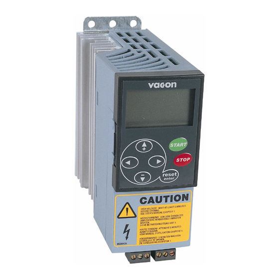
• 49 CONTROL KEYPAD The control keypad is the link between the Vacon frequency converter and the user. The Vacon NXL control keypad features a seven-segment display with seven indicators for the Run status (RUN, , READY, STOP, ALARM, FAULT) and three indicators for the control place (I/O term, Keypad, Bus/Comm). -
Page 50: Control Place Indications
50 • vacon Control keypad 7.1.2 Control place indications (See control keypad) I/O term, Keypad Bus/Comm The symbols (see chapter 7.4.3.1) indicate the choice of control place made in the Keypad control menu (see chapter 7.4.3). I/O term = I/O terminals are the selected control place; i.e. START/STOP commands or reference values are given through the I/O terminals. -
Page 51: Keypad Push-Buttons
Control keypad vacon • 51 Keypad push-buttons The Vacon seven-segment control keypad features 7 push-buttons that are used for the control of the frequency converter (and motor) and parameter setting. Figure 7-2. Keypad push-buttons 7.2.1 Button descriptions ENTER reset There are two operations integrated in this button. The button operates mainly as reset button except in the parameter edit mode. -
Page 52: Start-Up Wizard
Stop button serves also for activating the Start-up Wizard (see below) Start-up wizard Vacon NXL has a built-in start-up wizard, that speeds up the programming of the drive. The wizard helps you choose between four different operating modes, Standard, Fan, Pump and High Performance. -
Page 53: Navigation On The Control Keypad
From there you will be able to navigate your way up to the desired menu using the menu and browser buttons. More detailed descriptions of the menus you will find later in this Chapter. 24-hour support: +358-40-8371 150 • Email: vacon@vacon.com... - Page 54 54 • vacon Control keypad READ Y READ Y STOP I/O term STOP I/O term READ Y READ Y READ Y STOP I/O term STOP I/O term STOP I/O term READ Y READ Y READ Y STOP I/O term STOP...
- Page 55 S6.8 = System info S6.9 = AI mode S6.10 = Fieldbus parameters Parameters are described in chapter 7.4.6 E7.1 = Slot D Expander board menu E7.1 E7.2 E7.2 = Slot E Table 7-1. Main menu functions 24-hour support: +358-40-8371 150 • Email: vacon@vacon.com...
-
Page 56: Monitoring Menu (M1)
56 • vacon Control keypad 7.4.1 Monitoring menu (M1) You can enter the Monitoring menu from the Main menu by pushing the Menu button right when the location indication M1 is visible on the display. How to browse through the monitored values is presented in Figure 7-5. - Page 57 Shows the current drive configuration mode selected with startup wizard: 0 = No mode selected (Default) V1.25 Mode 1 = Standard 2 = Fan 3 = Pump 4 = High performance Table 7-2. Monitored signals 24-hour support: +358-40-8371 150 • Email: vacon@vacon.com...
-
Page 58: Parameter Menu (P2)
58 • vacon Control keypad 7.4.2 Parameter menu (P2) Parameters are the way of conveying the commands of the user to the frequency converter. The Parameter Menu Main Menu parameter values can be edited by entering the from the when the location indication P2 is visible on the display. - Page 59 I/O term READY READY READY STOP I/O term STOP I/O term STOP I/O term READY READY READY STOP STOP STOP I/O term I/O term I/O term enter nxlk17.fh8 Figure 7-6. Parameter value change procedure 24-hour support: +358-40-8371 150 • Email: vacon@vacon.com...
-
Page 60: Keypad Control Menu (K3)
60 • vacon Control keypad 7.4.3 Keypad control menu (K3) In the Keypad Controls Menu , you can choose the control place, edit the frequency reference and Menu button right change the direction of the motor. Enter the submenu level with the... -
Page 61: Keypad Reference
0, the STOP button will stop the motor only when the keypad has been selected as the active control place. See Figure 7-7 for how to change the value of this parameter. 24-hour support: +358-40-8371 150 • Email: vacon@vacon.com... -
Page 62: Active Faults Menu (F4)
62 • vacon Control keypad 7.4.4 Active faults menu (F4) Active faults menu can be entered from the Main menu by pushing the Menu button right when the location indication F4 is visible on the keypad display. The memory of active faults can store the maximum of 5 faults in the order of appearance. The... -
Page 63: Fault Codes
Motor overheating has been detected by Decrease the motor load. overtemperature frequency converter motor temperature If no motor overload exists, check the model. Motor is overloaded. temperature model parameters. Motor underload Motor underload protection has tripped. 24-hour support: +358-40-8371 150 • Email: vacon@vacon.com... - Page 64 Master and the fieldbus board is If installation is correct contact the broken nearest Vacon distributor Please visit: http://www.vacon.com Slot fault Defective option board or slot Check board and slot. Contact the nearest Vacon distributor Please visit: http://www.vacon.com Telephone: +358-201-2121 • Fax: +358-201-212 205...
-
Page 65: Fault History Menu (H5)
2 to 3 seconds resets the whole fault history. READY READY READY S T OP I/O term S T OP I/O term S T OP I/O term nxlk20.fh8 Push Enter to reset! Figure 7-9. Fault history menu 24-hour support: +358-40-8371 150 • Email: vacon@vacon.com... -
Page 66: System Menu (S6)
66 • vacon Control keypad 7.4.6 System menu (S6) System menu can be entered from the main menu by pushing the Menu button right when the location indication S6 is visible on the display. The controls associated with the general use of the frequency converter, such as keypad settings, customised... - Page 67 5=9600 baud 6=19200 baud 7=38400 baud 8=57600 baud P6.10.5 Stop bits 0=1 1=2 P6.10.6 Parity type 0=None 1=Odd 2=Even 0=Not used1=1 second Communication P6.10.7 2=2 seconds, etc timeout Table 7-5. System menu functions 24-hour support: +358-40-8371 150 • Email: vacon@vacon.com...
-
Page 68: Copy Parameters
The Copy parameters submenu (S6.3) is located under the System menu. The Vacon NX frequency converter features a possibility for the user to store and load two customised parameter sets (all parameters included in the application, not the system menu parameters) and to load back the factory default parameter values. -
Page 69: Keypad Settings
READY READY READY STOP I/O term STOP I/O term STOP I/O term READY READY CONFIRM CHANGE STOP I/O term STOP I/O term enter nxlk23.fh8 Figure 7-12. Default page function 24-hour support: +358-40-8371 150 • Email: vacon@vacon.com... -
Page 70: Hardware Settings
70 • vacon Control keypad Timeout time (P6.6.3) The Timeout time setting defines the time after which the keypad display returns to the Default Page (P6.6.1), see above. Move to the Edit menu by pressing the Menu button right . Set the timeout time you want and confirm... -
Page 71: System Information
Info menu Menu button right Enter the by pressing the . Now you can browse through the information Browser buttons pages with the 24-hour support: +358-40-8371 150 • Email: vacon@vacon.com... - Page 72 72 • vacon Control keypad Counters submenu (S6.8.1) In the Counters submenu (S6.8.1) you can find information related to the frequency converter operation times, i.e. the total numbers of MWh, operation days and operation hours passed so far. Unlike the counters in the trip counters menu, these counters cannot be reset.
- Page 73 The selections are shown in Table 7-5. The keypad will also display the program version of the respective Browser buttons board when you push either one of the 24-hour support: +358-40-8371 150 • Email: vacon@vacon.com...
-
Page 74: Ai Mode
74 • vacon Control keypad For more information on the expander board-related parameters, see Chapter 7.4.8. READY READY S TO P I/O term S TO P I/O term nxlk27.fh8 Figure 7-16. Expander board information menu 7.4.6.6 AI mode The parameters P6.9.1 and P6.9.2 selects the analogue input mode. P6.9.1 appears only in classes MF4 –... -
Page 75: Modbus Interface
Read Holding Register All ID numbers Read Input Register All ID numbers Preset Single Register All ID numbers Preset Multiple Register All ID numbers Table 7-12. Modbus commands supported by NXL 24-hour support: +358-40-8371 150 • Email: vacon@vacon.com... -
Page 76: Termination Resistor
76 • vacon Control keypad 7.4.7.2 Termination Resistor The RS-485 bus is terminated with 120 Ω termination resistors in both ends. NXL has a built-in termination resistor which is switched off as a default. See the jumper selections in chapter 6.2.5.1 7.4.7.3... - Page 77 Control word In Vacon applications, the three first bits of the control word are used to control the frequency converter. However, you can customise the content of the control word for your own applications because the control word is sent to the frequency converter as such.
-
Page 78: Fieldbus Parameters
78 • vacon Control keypad 7.4.7.5 Fieldbus parameters RS-485 communication status (I6.10.1) With this function you can check the status of the RS 485 bus. If the bus is not in use, this value is 0. xx.yyy xx = 0 – 64 (Number of messages containing errors) yyy = 0 –... - Page 79 If communication between two messages is broken for a longer time than that defined by this parameter, a communication error is initiated. If the value of this parameter is 0, the function is not used. 0 = Not used 1 = 1 second 2 = 2 seconds, etc 24-hour support: +358-40-8371 150 • Email: vacon@vacon.com...
-
Page 80: Expander Board Menu (E7)
. You can view and edit the parameter values in the same way as described in chapter 7.4.2. Further keypad functions The Vacon NXL control keypad embodies additional application-related functions. See Vacon Multicontrol Application Manual for more information. Telephone: +358-201-2121 • Fax: +358-201-212 205... -
Page 81: Commissioning
The motor terminals U, V, W and the DC-link/brake resistor terminals –/+ are live when Vacon NXL is connected to mains, even if the motor is not running. WARNING The control I/O-terminals are isolated from the mains potential. - Page 82 82 • vacon Commissioning Check that all Start/Stop switches connected to the I/O terminals are in Stop-position. Connect the frequency converter to mains. Set the parameters of group 1 according to the requirements of your application. At least the following parameters should be set:...
- Page 83 Connect the motor to the process (if the startup test was run without the motor being connected) a) Before running the tests, make sure that this can be done safely. b) Inform your co-workers of the tests. c) Repeat test 8A or 8B. 24-hour support: +358-40-8371 150 • Email: vacon@vacon.com...
-
Page 84: Basic Parameters
84 • vacon Commissioning Basic parameters On the next pages you will find the list of parameters that are essential for the commissioning of the frequency converter. You will find more details of these and other special parameters in the Multi- Control Application manual. -
Page 85: Basic Parameters (Control Keypad: Menu P2 B2.1)
4=Motor potentiometer 5=AI1/AI2 selection Not used if AI2 Custom min > 0% or AI2 custom max. < 100% P2.1.15 AI2 signal range 1=0mA – 20mA 2=4mA – 20mA 3=0V – 10V 4=2V – 10V 24-hour support: +358-40-8371 150 • Email: vacon@vacon.com... - Page 86 86 • vacon Commissioning 0=Not used 1=Output freq. (0—f 2=Freq. reference (0—f 3=Motor speed (0—Motor nominal speed) 4=Output current (0— nMotor Analogue output 5=Motor torque (0—T nMotor P2.1.16 function 6=Motor power (0—P nMotor 7=Motor voltage (0— nMotor 8=DC-link volt (0—1000V) 9=PI controller ref.
-
Page 87: Fault Tracing
Overtemperature warning is issued when Check the heatsink for dust. Check the ambient temperature. the heatsink temperature exceeds 85°C. Make sure that the switching frequency is not too high in relation to ambient temperature and motor load. 24-hour support: +358-40-8371 150 • Email: vacon@vacon.com... - Page 88 88 • vacon Fault tracing Motor stalled Motor stall protection has tripped. Check motor. Motor Motor overheating has been detected by Decrease the motor load. overtemperature frequency converter motor temperature If no motor overload exists, check the model. Motor is overloaded.
- Page 89 Contact the nearest Vacon distributor. Please visit: http://www.vacon.com Actual value Actual value has exceeded or fallen below supervision (depending on par. 2.7.22) the actual value supervision limit (par. 2.7.23) Table 9-1. Fault codes 24-hour support: +358-40-8371 150 • Email: vacon@vacon.com...
-
Page 90: Description Of Expander Board Opt-Aa
DESCRIPTION OF EXPANDER BOARD OPT-AA Description: I/O expander board with one relay output, one open collector output and three digital inputs. Allowed slots: Vacon NXL board slot E Type ID: 16705 Terminals: Two terminal blocks; Screw terminals (M2.6 and M3); No coding... -
Page 91: Description Of Expander Board Opt-Ai
• 91 DESCRIPTION OF EXPANDER BOARD OPT-AI Description: I/O expander board with one relay output (NO), three digital inputs and one thermistor input for Vacon NXL frequency converters Allowed slots: Vacon NXL board slot E Type ID: 16713 Terminals: Three terminal blocks;... - Page 92 92 • vacon board opt-ai I/O terminals on OPT-AI Terminal Parameter Description setting +24V Control voltage output; voltage for switches etc, max. 150 mA Ground for controls, e.g for +24 V and DO DIN1 DIGIN:B.1 Digital input 1 DIN2 DIGIN:B.2...
Need help?
Do you have a question about the NXL series and is the answer not in the manual?
Questions and answers