Table of Contents
Advertisement
Quick Links
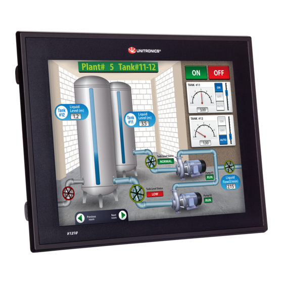
Vision™ OPLC™
This guide provides basic information for Unitronics' controllers V1210-T20BJ.
General Description
V1210 OPLCs are programmable logic controllers that comprise a built-in operating panel containing
a 12.1" Color Touchscreen.
Communications
I/O Options
Information Mode
Programming
Software,
& Utilities
Unitronics
2 isolated RS232/RS485 ports
USB programming port (Mini-B)
Isolated CANbus port
The user can order and install an additional port. This may be
either Ethernet or serial.
Communication Function Blocks include: SMS, GPRS, MODBUS
serial/IP; Protocol FB enables PLC to communicate with almost
any external device, via serial or Ethernet communications
V1210 supports digital, high-speed,
analog, weight and temperature
measurement I/Os via:
Snap-in I/O Modules
Plug into the back of the
controller to provide an on-
board I/O configuration
I/O Expansion Modules
Local or remote I/Os may be
added via expansion port or
CANbus.
Installation instructions and other data may be found in the module's technical
specification sheet.
This mode enables you to:
Calibrate the touchscreen
View & Edit operand values, COM port settings, RTC and screen
contrast/brightness settings
Stop, initialize, and reset the PLC
To enter Information Mode, press the touchscreen and maintain contact for
several seconds.
The Unitronics Setup CD contains VisiLogic software and other utilities
VisiLogic
Easily configure hardware and write both HMI and Ladder control
applications; the Function Block library simplifies complex tasks
such as PID. Write your application, and then download it to the
controller via the programming cable included in the kit.
Utilities
These include UniOPC server, Remote Access for remote
programming and diagnostics, and DataXport for run-time data
logging.
To learn how to use and program the controller, as well as use utilities such as
Remote Access, refer to the VisiLogic Help system.
Installation Guide
V1210-T20BJ
1
Advertisement
Table of Contents

Related Manuals for Unitronics V1210-T20BJ


Summary of Contents for Unitronics V1210-T20BJ
-
Page 1: General Description
Vision™ OPLC™ Installation Guide V1210-T20BJ This guide provides basic information for Unitronics’ controllers V1210-T20BJ. General Description V1210 OPLCs are programmable logic controllers that comprise a built-in operating panel containing a 12.1” Color Touchscreen. 2 isolated RS232/RS485 ports Communications USB programming port (Mini-B) ... -
Page 2: Environmental Considerations
All examples and diagrams are intended to aid understanding, and do not guarantee operation. Unitronics accepts no responsibility for actual use of this product based on these examples. Please dispose of this product according to local and national standards and regulations. - Page 3 Vision™ OPLC™,V1210-T20BJ Installation Guide Inserting the Battery In order to preserve data in case of power-off, you must insert the battery. The battery is supplied taped to the battery cover on the rear of the controller. 1. Remove the battery cover shown on page 4. The polarity (+) is marked on the battery holder and on the battery.
- Page 4 Vision™ OPLC™,V1210-T20BJ Installation Guide Panel Mounting Before you begin, note that the mounting panel cannot be more than 5 mm thick. 1. Make a panel cut-out according to the dimensions in the figure to the right. 2. Slide the controller into the cut- out, ensuring that the rubber seal is in place.
-
Page 5: Power Supply
4. Tighten enough to keep the wire from pulling free. Power Supply The controller V1210-T20BJ requires either an external 12 or 24VDC power supply. Permissible input voltage range: 10.2-28.8VDC, with less than 10% ripple. The power supply must include double insulation. Outputs must be rated as SELV/PELV/Class 2/Limited Power. -
Page 6: Communication Ports
Vision™ OPLC™,V1210-T20BJ Installation Guide Communication Ports This series comprises a USB port, 2 RS232/RS485 serial ports and a CANbus port. An additional port may be ordered separately and installed. This port may be either Ethernet, or serial (COM 3). For the most updated information regarding ports and their installation, please refer to the Technical Library at www.unitronics.com. - Page 7 Vision™ OPLC™,V1210-T20BJ Installation Guide RS232/RS485: DIP Switch Settings The settings below are for each COM port. Switch Settings RS232* RS485 RS485 with termination** *Default factory setting **Causes the unit to function as an end unit in an RS485 network Installing a Snap-in I/O Module ...
- Page 8 CANbus Connector The information in this document reflects products at the date of printing. Unitronics reserves the right, subject to all applicable laws, at any time, at its sole discretion, and without notice, to discontinue or change the features, designs, materials and other specifications of its products, and to either permanently or temporarily withdraw any of the forgoing from the market.
Need help?
Do you have a question about the V1210-T20BJ and is the answer not in the manual?
Questions and answers