Table of Contents
Advertisement
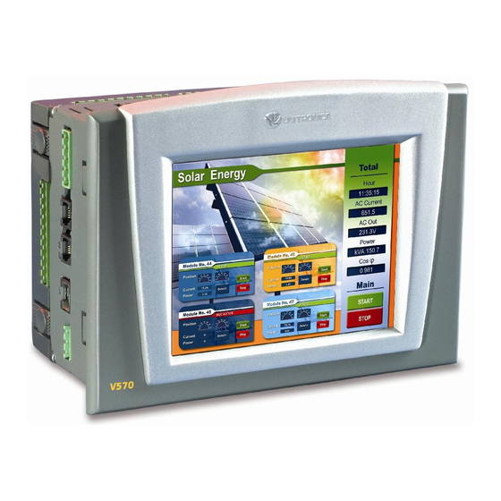
Vision™ OPLC™
This guide provides basic information for Unitronics' controllers V570-57-T20B and V570-57-T40B.
General Description
Vision OPLCs are programmable logic controllers that comprise an integral operating panel.
V570-57-T20B and V570-57-T40B comprise a color touchscreen, which displays a virtual keyboard
when the application requires the operator to enter data.
Communications
I/O Options
Information Mode
Programming
Software,
& Utilities
1
Number of I/Os may vary according to I/O module selection.
Unitronics
2 isolated RS232/RS485 ports
Isolated CANbus port, CANopen & UniCAN
The user can order and install an Ethernet port
Communication Function Blocks include: SMS, GPRS, MODBUS
serial/IP Protocol FB enables PLC to communicate with almost any
external device, via serial or Ethernet communications
Vision supports up to 512
high-speed, and analog I/Os via:
Snap-in I/O Modules
Plug into the back of the
controller to provide an on-
board I/O configuration
I/O Expansion Modules
Via adaptor, local or remote
I/Os may be added via
expansion port or CANbus
Installation instructions and other data may be found in the module's technical
specification sheet.
This mode enables you to:
Calibrate the touchscreen
View & Edit operand values, COM port settings, RTC and screen
contrast/brightness settings
Stop, initialize, and reset the PLC
To enter Information Mode, press the touchscreen and maintain contact for
several seconds.
The Unitronics Setup CD contains VisiLogic software and other utilities
VisiLogic
Easily configure hardware and write both HMI and Ladder control
applications; the Function Block library simplifies complex tasks
such as PID. Write your application, and then download it to the
controller via the programming cable included in the kit.
Utilities
These include UniOPC server, Remote Access for remote
programming and diagnostics, and DataXport for run-time data
logging.
To learn how to use and program the controller, as well as use utilities such as
Remote Access, refer to the VisiLogic Help system.
Installation Guide
V570-57-T20B and V570-57-T40B
1
digital,
1
Advertisement
Table of Contents

Related Manuals for Unitronics V570-57-T20B


Summary of Contents for Unitronics V570-57-T20B
-
Page 1: General Description
This guide provides basic information for Unitronics’ controllers V570-57-T20B and V570-57-T40B. General Description Vision OPLCs are programmable logic controllers that comprise an integral operating panel. V570-57-T20B and V570-57-T40B comprise a color touchscreen, which displays a virtual keyboard when the application requires the operator to enter data. 2 isolated RS232/RS485 ports Communications Isolated CANbus port, CANopen &... -
Page 2: Environmental Considerations
All examples and diagrams are intended to aid understanding, and do not guarantee operation. Unitronics accepts no responsibility for actual use of this product based on these examples. Please dispose of this product according to local and national standards and regulations. - Page 3 Installation Guide Vision™ OPLC™ V570-57-T20B, V570-57-T40B Inserting the Battery In order to preserve data in case of power-off, you must insert the battery. The battery is supplied taped to the battery cover on the rear of the controller. 1. Remove the battery cover shown on page 4. The polarity (+) is marked on the battery holder and on the battery.
- Page 4 Vision™ OPLC™ V570-57-T20B, V570-57-T40B Installation Guide Panel Mounting Before you begin, note that the mounting panel cannot be more than 5 mm thick. 1. Make a panel cut-out according to the dimensions in the figure to the right. 2. Slide the controller into the cut- out, ensuring that the rubber seal is in place.
-
Page 5: Power Supply
Installation Guide Vision™ OPLC™ V570-57-T20B, V570-57-T40B Wiring Do not touch live wires. Unused pins should not be connected. Ignoring this directive may damage the device. To avoid damaging the wire, do not exceed a maximum torque of 0.5 N·m (5 kgf·cm). -
Page 6: Communication Ports
Vision™ OPLC™ V570-57-T20B, V570-57-T40B Installation Guide Communication Ports This series comprises 2 RS232/RS485 serial ports and a CANbus port. Turn off power before making communications connections. Always use the appropriate port adapters. Caution Serial Communications The serial ports are type RJ-11 and may be set to either RS232 or RS485 via DIP switches, in accordance with the table shown below. - Page 7 Installation Guide Vision™ OPLC™ V570-57-T20B, V570-57-T40B Removing a Snap-in I/O Module 1. Locate the four buttons on the sides of the controller, two on either side. 2. Press the buttons and hold them down to open the locking mechanism. 3. Gently rock the module from side to side, easing the module from the controller.
- Page 8 The information in this document reflects products at the date of printing. Unitronics reserves the right, subject to all applicable laws, at any time, at its sole discretion, and without notice, to discontinue or change the features, designs, materials and other specifications of its products, and to either permanently or temporarily withdraw any of the forgoing from the market.
Need help?
Do you have a question about the V570-57-T20B and is the answer not in the manual?
Questions and answers