Table of Contents
Advertisement
User'
User' s s s s s
User'
User'
User'
Manual
Manual
Manual
Manual
Manual
An
An
AMD Sock k k k k et
AMD Soc
AMD Soc
An
An
An AMD Soc
AMD Soc
mainboard (100/133MHz)
mainboard (100/133MHz)
mainboard (100/133MHz)
mainboard (100/133MHz)
mainboard (100/133MHz)
Suppor
Suppor
ts PC133/V
ts PC133/V
Suppor
Suppor
Suppor ts PC133/V
ts PC133/VC133 Memor
ts PC133/V
TRADEMARK
All products and company names are trademarks or registered
trademarks of their respective holders.
These specifications are subject to change without notice.
et et A Pr
et et
A Pr
A Pr
ocessor based
ocessor based
A Pr
A Processor based
ocessor based
ocessor based
C133 Memor
C133 Memor
C133 Memor y Modules
C133 Memor
Manual Revision 1.0
May 18, 2001
y Modules
y Modules
y Modules
y Modules
Advertisement
Table of Contents

Related Manuals for EPOX EP-8kem


Summary of Contents for EPOX EP-8kem
- Page 1 User’ User’ s s s s s User’ User’ User’ Manual Manual Manual Manual Manual AMD Soc AMD Sock k k k k et AMD Soc et et et et A Pr A Pr A Pr ocessor based ocessor based An AMD Soc AMD Soc A Pr...
-
Page 3: Table Of Contents
Table of Contents Page Section 1 Introduction Components Checklist ........1-1 Overview AMD Duron & Athlon Processors ..... 1-2 Ultra ATA66/100 ..........1-3 Hardware Monitoring .......... 1-3 Mainboard Form-Factor ........1-4 I/O Shield Connector .......... 1-5 Power-On/Off (Remote) ........1-5 System Block Diagram ........ - Page 4 Integrated Peripherals ......... 4-12 Power Management Setup ........4-17 PNP/PCI Configuration Setup ......4-20 PC Health Status ..........4-22 Frequency/Voltage Control ......... 4-23 Defaults Menu ............. 4-24 Supervisor/User Password Setting ..... 4-25 Exit Selecting ............4-26 Section 5 Driver Installation Easy Driver Installation ........
-
Page 5: Introduction
Introduction Section 1 INTRODUCTION Components Checklist Mainboard User’s manual Floppy ribbon cable ATA-66/100 Hard drive ribbon cable USB Cable Driver and utility USER’S MANUAL Page 1-1... -
Page 6: Overview
Introduction Overview AMD Duron & Athlon Processors The AMD Athlon is a seventh-generation micro architecture with an integrated L2 cache, which is powerful enough to support the bandwidth requirements of a large range of applications, hardware, graphics, and memory technologies. These processors implement advanced design techniques such as: Socket A (PGA 462) 200/266MHz system interface based on the Alpha™... -
Page 7: Ultra Ata66/100
Introduction The AMD Duron processor is derived from the AMD Athlon processor core. It features full-speed, on-chip cache memory, a 200MHz front side system bus, and enhanced 3DNow!™ technology. Although both processors are related, there are key differences. The AMD Athlon processor is targeted at the performance segment, and as such will have more cache memory and higher clock speeds. -
Page 8: Mainboard Form-Factor
Introduction Mainboard Form-Factor The board is designed with Micro ATX form factor - the new industry standard of chassis. Micro ATX form factor is essentially a Baby-AT baseboard rotated 90 degrees within the chassis enclosure and a new mounting configuration for the power supply. -
Page 9: I/O Shield Connector
Introduction I/O Shield Connector The board is equipped with an I/O back panel. Please use the appropriate I/O shield (figure 3). Joystick/Midi parallel port PS/2 Mouse USB port PS/2 Keyboard COM1 VGA1 Speaker Figure 3: I/O back panel layout Line_in Power-On/Off (Remote) The board has a single 20-pin connector for ATX power supplies. -
Page 10: System Block Diagram
Introduction System Block Diagram Socket A Processors 133/100MHz 133/100MHz PCI Bridge and memory controller KLE133 C-Media CMI8738 VT82C686B I/O Bridge (ATA66/100) USB 0,1 USB 2,3 Figure 5: System Block Diagram Page 1-6... -
Page 11: Features
Features Section 2 FEATURES Mainboard Features: PROCESSOR - AMD Athlon , Duron Processors, Socket A, operating at 600MHz ~ 1GHz CHIPSET - VIA KLE133 AGPset (KLE133 + 686B) DRAM MODULE - 168pin DIMM x 2 for PC133/VC133 Memory - DRAM Size: 32MB to 1GB EXPANSION SLOT - PCI x 3 - Panel Link slot x 1... - Page 12 Features - USB connector x 4 (2 for Optional) BIOS - Award Plug & Play BIOS Built-in VGA with Trident Blade 3D core C-Media CMI8738/PCI-SX PCI sound chip EXTENDED FUNCTION - Supports exclusive USDM(Unified System Diagnostic Manager) and Hardware Monitoring Function by VT82C686B - Supports exclusive KBPO (KeyBoard Power On) - Supports Power Loss Recovery Function - Supports STR (Suspend To RAM) power saving Function...
-
Page 13: Installation
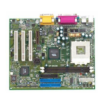
Installation Section 3 INSTALLATION Mainboard Detailed Layout Figure 1 Page 3-1... -
Page 14: Section
Installation Easy Installation Procedure The following must be completed before powering on your new system: 3-1. CPU Insertion 3-2. Jumper Settings 3-3. System memory Configuration 3-4. Device Connectors 3-5. External Modem Ring-in Power ON and Keyboard Power ON Functions (KBPO) 3-6. - Page 15 Installation Step 3 Close the socket by lowering and locking the actuation lever. Figure 4 Step 4 Thermal compound and qualified heatsink recommended by AMD are a must to avoid CPU overheat damage. For more information about installing your CPU, please refer to the AMD website article “Socket A AMD processor and Heatsink Installation Guide”...
-
Page 16: Jumper Settings
Installation Section 3-2 Jumper Settings The mainboard was designed with very few jumpers to make your installation faster and easier. CMOS Clear JP1 = 1-2 Normal (Default) = 2-3 Clear CMOS STR Function JP2 = 1-2 Disabled (Default) = 2-3 Enabled Power Loss Recovery JP3 = 1-2 Disabled (Default) = 2-3 Enabled... - Page 17 Installation Keyboard Power-ON Function JP4 = 1-2 Disabled (Default) = 2-3 Enabled CPU Host Clock Select JP5 = 1-2 100MHz (Default) = 2-3 133MHz Onboard CMI8738 audio JP6 = 1-2 Enabled (Default) = 2-3 Disabled Page 3-5...
-
Page 18: System Memory Configuration
Installation Section 3-3 System Memory Configuration Memory Layout The board supports (2) PC133/VC133 168-pin DIMMs (Dual In-line Memory Module). The DIMMs is for SDRAM (Synchronous DRAM). • SDRAM may be 83MHz (12ns), 100MHz (10ns), 125MHz (8ns) or 133MHz (7.5ns) bus speed. •... -
Page 19: Dimm Module Installation
Installation DIMM Module Installation Figure 7 displays the notch marks and what they should look like on your DIMM memory module. DIMMs have 168-pins and two notches that will match with the onboard DIMM socket. DIMM modules are installed by placing the chip firmly into the socket at a 90 degree angle and pressing straight down (figure 8) until it fits tightly into the DIMM socket (figure 9). -
Page 20: Device Connectors
Installation Section 3-4 Device Connectors parallel port Joystick/Midi port PS/2 Mouse USB port PS/2 KEYBOARD COM1 VGA1 Speaker Line_in Figure 10 J2,J3: Chassis Panel Connector • Power_LED, Speaker, Reset, Power ON/Off, Turbo LED, HDD LED, IR Conn., CPU Fan Power •... - Page 21 Installation AUX1: Auxiliary Line_IN Connector • Pin1(Left Line_IN), Pin2/Pin3(GND), Pin4(Right Line-IN) USB2: USB port header pins for adding two additional USB ports. -Data +Data +Data -Data USB port header pin descriptions. Page 3-9...
- Page 22 Installation Device Connectors (continued) (This is connected to the power button on the case. Using the Soft-Off by Pwr-BTTN feature, you can choose either Instant Off (turns system off immediately), or 4 sec delay (you need to push the button down for 4 seconds before the system turns off).
- Page 23 Installation Device Connectors (continued) PL3 Connector (Digital Video Out interface for digital display). EP-PL3 Flat Panel Slot Digital display (DTFP) * The EP-PL3 adapter card (optional) Page 3-11...
-
Page 24: Keyboard Power On Function (Kbpo)
Installation Section 3-5 External Modem Ring-in Power ON and Keyboard Power ON Functions (KBPO) On the basis of bounded functions in I/O chipset, the two serial ports are able to support the External Modem Ring-in Power ON function. Once users connect the external modem to COM1 or COM2, the mainboard allows users to turn on their system through the remote and host's dial-up control. -
Page 25: Str (Suspend To Ram) Function
Installation 3-6 STR (Suspend To RAM) Function The board supports the STR power management state by maintaining the appropriate states on the SDRAM interface signals. The power source must be kept alive to the SDRAM during STR (ACPI S3). Advanced Configuration Power Interface (ACPI) provides more Energy Saving Features for operating systems that supporting Instant ON and QuickStart function. - Page 26 Installation d. You must push the Power button connected with onboard J3 pin to wake up you system (not to click to mouse or press keyboard to wake up the system). Just pushing Power button, your system will quickly back to the last screen for you.
- Page 27 Installation Page Left Blank Page 3-15...
-
Page 28: Award Bios Setup
BIOS Section 4 AWARD BIOS SETUP Main Menu Award’s ROM BIOS provides a built-in Setup program which allows user to modify the basic system configuration and hardware parameters. The modified data will be stored in a battery-backed CMOS, so that data will be retained even when the power is turned off. -
Page 29: Standard Cmos Setup
BIOS The menu displays all the major selection items. Select the item you need to reconfigure. The selection is made by moving the cursor (press any direction key ) to the item and pressing the ‘Enter’ key. An on-line help message is displayed at the bottom of the screen as the cursor is moved to various items which provides a better understanding of each function. -
Page 30: Advanced Bios Features
BIOS NOTE: If the hard disk Primary Master/Slave and Secondary Master/ Slave are set to Auto, then the hard disk size and model will be auto-detected. NOTE: The “Halt On:” field is used to determine when to halt the system by the BIOS if an error occurs. - Page 31 BIOS Virus Warning: During and after the system boots up, any attempt to write to the boot sector or partition table of the hard disk drive will halt the system and an error message will appear. You should then run an anti-virus program to locate the virus. Keep in mind that this feature protects only the boot sector, not the entire hard drive.
- Page 32 BIOS First /Second/Third/Other Boot Device: The BIOS attempts to load the operat- ing system from the devices in the sequence selected in these items. The choice: Floppy, LS120, HDD-0, SCSI, CDROM, HDD-1, HDD-2, HDD-3, ZIP100, USB-FDD, USB-ZIP, USB-CDROM, USB-HDD, LAN, Disabled. Swap Floppy Drive: This will swap your physical drive letters A &...
- Page 33 BIOS Typematic Rate (Chars/Sec): This is the number of characters that will be repeated by a keyboard press. The default is 6. 6: 6 characters per second. 8: 8 characters per second. 10: 10 characters per second. 12: 12 characters per second. 15: 15 characters per second.
- Page 34 BIOS D8000 - DBFFF Shadow: DC000 - DFFFF Shadow: These categories determine whether ROMs from option cards will be copied into RAM. This will be in 16K byte or 32K byte units, and the size will depend on chipset of the option card. Enabled: Optional shadow is enabled.
-
Page 35: Advanced Chipset Features
BIOS 4-3 Advanced Chipset Features Choose the “CHIPSET FEATURES SETUP” in the CMOS SETUP UTILITY menu to display following menu. Figure 4: Chipset Features Setup DRAM Timing By SPD: Select Enabled for setting SDRAM timing by SPD. The Choice: Enabled, Disabled. DRAM Clock : The item will synchronize/asynchronize DRAM operation clock. - Page 36 BIOS DRAM Prechange to Active: The choice: 2T, 3T DRAM Active to Prechange: The choice: 5T, 6T DRAM Active to CMD: The choice: 2T, 3T DRAM Page-Mode: The item will active or inactive chipset page registers. Enabled: Page-Mode Enabled. Disabled: No page registers update and non Page-Mode operation. Memory Hole : You can reserve this memory area for the use of ISA adaptor ROMs.
- Page 37 BIOS Frame Buffer Size: This item allows you to control the VGA frame buffer size. The choice: 2M, 4M, 8M. AGP Aperture Size: The amount of system memory that the AGP card is allowed to share. The default is 64. 4MB of systems memory accessable by the AGP card.
- Page 38 BIOS PCI Dynamic Bursting: When Enabled, data transfers on the PCI bus, where possible, make use of the high-performance PCI bust protocol, in which graeater amounts of data are transferred at a single command. The Choice: Enabled, Disabled. PCI Master 0 WS Write: When Enabled, writes to the PCI bus are command with zero wait states.
-
Page 39: Integrated Peripherals
BIOS 4-4 Integrated Peripherals Figure 5: Integrated Peripherals Note: If you do not use the Onboard IDE connector, then you will need to set Onboard Primary PCI IDE: Disabled and Onboard Secondary PCI IDE: Disabled Note: The Onboard PCI IDE cable should be equal to or less than 18 inches (45 cm.). - Page 40 BIOS Primary Master PIO: The default is Auto. Auto: BIOS will automatically detect the Onboard Primary Master PCI IDE HDD Accessing mode. Mode 0~4: Manually set the IDE Programmed interrupt mode. Primary Slave PIO: The default is Auto. Auto: BIOS will automatically detect the Onboard Primary Slave PCI IDE HDD Accessing mode.
- Page 41 BIOS Init Display First: If two video cards are used (1 AGP and 1 PCI) this specifies which one will be the primary display adapter. The default is PCI Slot. PCI Slots: PCI video card will be primary adapter. AGP: AGP video card will be primary adapter.
- Page 42 BIOS UART 2 Mode: This item allows you to determine which Infra Red (IR) function of onboard I/O chip. The Choice: Standard, ASKIR, HPSIR. Onboard Parallel port: This field allows the user to configure the LPT port. The default is 378H / IRQ7. 378H: Enable Onboard LPT port and address is 378H and IRQ7.
- Page 43 BIOS MPU-401 I/O Address: Built-in MPU-401 compatible MIDI I/O port selection: 300-303H 310-313H 320-323H 330-333H (default) Game Port (200-207H): Built-in joystick port support disabled/enabled(default). Page 4-16...
-
Page 44: Power Management Setup
BIOS 4-5 Power Management Setup Choose the “POWER MANAGEMENT SETUP” in the CMOS SETUP UTILITY to display the following screen. This menu allows the user to modify the power management parameters and IRQ signals. In general, these parameters should not be changed unless it’s absolutely necessary. - Page 45 BIOS ACPI Suspend Type: This item allows you to select S1(POS) or S3(STR) function. The choice: S1(POS), S3(STR). PM controlled by APM: This option shows weather or not you want the Power Management to be controlled the Advanced Power Management (APM). The default is Yes.
- Page 46 BIOS Instant Off: Turns off the system instantly. Delay 4 Second : Turns off the system after a 4 second delay. If momentary press of button, the system will go into Suspend Mode. Press the power botton again to take system out of Suspend Mode. State After Power Failure: This field lets you determine the state that your PC returns to after a power failure.
-
Page 47: Pnp/Pci Configuration Setup
BIOS 4-6 PNP/PCI Configuration The PNP/PCI configuration program is for the user to modify the PCI/ISA IRQ signals when various PCI/ISA cards are inserted in the PCI or ISA slots. WARNING: Conflicting IRQ’s may cause the system to not find certain devices. Figure 7: PCI Configuration Setup PNP OS Installed: Do you have a PNP OS installed on your system. - Page 48 BIOS Reset Configuration Data: This setting allows you to clear ESCD data. The default is Disabled Disabled: Normal Setting. Enabled: If you have plugged in some Legacy cards to the system and they were recorded into ESCD (Extended System Configuration Data), you can set this field to Enabled in order to clear ESCD.
-
Page 49: Pc Health Status
BIOS 4-7 PC Health Status C/87 C/32 6135 RPM 0 RPM 1.62V 1.52V 3.22V 5.01V 12.12V Current CPU Temperature: This is the current temperature of the CPU. Current System Temperature: This is the Current temperature of the system. Current CPU FAN Speed: The current CPU fan speed in RPMs. Current Chassis FAN Speed: The current chassis fan speed in RPMs. -
Page 50: Frequency/Voltage Control
BIOS 4-8 Frequency/Voltage Control Auto Detect DIMM/PCI Clk: When enabled the motherboard will automatically disable the clock source for a DIMM socket which does not have a module in it. Same applies for PCI slots. The default is Enabled. Enabled: Enables this option. Disabled: Disables this option. -
Page 51: Defaults Menu
BIOS 4-9 Defaults Menu Selecting “Defaults” from the main menu shows you two options which are described below Load Fail-Safe Defaults When you press <Enter> on this item you get a confirmation dialog box with a message similar to: Load Fail-Safe Defaults (Y/N) ? N Pressing ‘Y’... -
Page 52: Supervisor/User Password Setting
BIOS 4-10 Supervisor/User Password Setting You can set either supervisor or user password, or both of then. The differences between are: supervisor password : can enter and change the options of the setup menus. user password : just can only enter but do not have the right to change the options of the setup menus. -
Page 53: Exit Selecting
BIOS 4-11 Exit Selecting Save & Exit Setup Pressing <Enter> on this item asks for confirmation: Save to CMOS and EXIT (Y/N)? Y Pressing “Y” stores the selections made in the menus in CMOS – a special section of memory that stays on after you turn your system off. The next time you boot your computer, the BIOS configures your system according to the Setup selec- tions stored in CMOS. -
Page 54: Driver Installation
Drivers Installation Section 5 Driver Installation Easy Driver Installation Insert the bundled autorun driver CD-disk. Step 1 : Click SERVICE PACK 4IN1 DRIVER. Install all components recommended. Step 2 : Click VGA DRIVER to install VGA Driver. Step 3 : Click C-MEDIA 8738 AUDIO DRIVER to install Audio Sound Driver. - Page 55 Drivers Installation Page Left Blank Page 5-2...
-
Page 56: Pci Audio Sound
PCI Audio Sound Section 6 PCI Audio Sound CMI8738 Features: Special Features PCI Plug and Play (PnP) bus interface, 32 bit PCI bus master. Full duplex playback and recording, built-in 16 bits CODEC. ® ® HRTF 3D positional audio, supports both Direct Sound 3D &... - Page 57 PCI Audio Sound Connectors and Jumper setting informations : s l : s l r e t . n i i f i r e t h t i i t s r e t Page 6-2...
- Page 58 PCI Audio Sound Dos Installation Before beginning the installation, please make sure that your hard disk has sufficient space(min. 4MB). Insert the Driver CD into the CD-ROM Drive. 1. Change directory to PCI audio DOS drivers folder (ex. D:\DOSDRV) at DOS prompt, and type: INSTALL [Enter] 2.
- Page 59 PCI Audio Sound 8. Click “start” key 9. Select “Run” 10.Key in the drive and path for Windows application installation program, for example, “D:\W95-98\APP\SETUP.EXE” 11. Click “OK” to start the installation procedure, and follow the on-screen instructions to finish the installation. When all the application softwares have been installed, please shut down Windows 95/98 system, and reboot your system.
- Page 60 PCI Audio Sound Windows NT 4.0 Installation We recommend that you install Windows NT 4.0 before you install this onboard’s PCI audio , and you not install any other sound card device drivers in your current system. 1. Click “Start” button, move the highlight bar to “Setting” item, and select the “Control Panel”.
- Page 61 PCI Audio Sound Windows Appc. (The Audio Rack) Introduction By means of a user-friendly interface(as easy as operating your home stereo system), this PCI audio rack provides you with the control over your PC’s audio functions, including the advantage of four speakers mode enable/ disable. Page 6-6...
- Page 62 PCI Audio Sound This Audio Rack consists of several major components: Control Center: Controls the display of the PCI Audio Rack’s components. MIDI Player: Plays MIDI music files, and allows you to create your personal song playlists, and play the song files. MP3/Wave Player: Records and plays digital audio (mp3/wave) files.
- Page 63 PCI Audio Sound System Mixer System Mixer allows you to control all the audio output and input levels. System Mixer displays the volume controls which your audio drivers make available. The names for these controls may vary. Mixer panel while the four speakers mode is enabled. Mixer panel while the four speakers mode is disabled.
- Page 64 PCI Audio Sound Mic: Controls the microphone input level. Wave: Controls wave (voice) playback or the recording levels. FM: Controls the FM music playback or the recording level. Aux-in: Controls the Aux-in music play or the recording level. CD: Controls the CD drive output level, for CD drives configured to play their audio output through the PC’s audio hardware.
- Page 65 PCI Audio Sound The 4 Speakers System This Audio Adapter provides 2 wave channels(front/rear), known as the 4 speakers ® ® system. When games or application programs via DirectSound 3D or A3D interface locate the sound sources to the listener’s back, the two rear speakers will work to enhance the rear audio positional effect, so as to complement the insufficiency of using only two front speakers to emulate the audio effect.
- Page 66 PCI Audio Sound 4.The demo Execute the “Helicopter” demo within the C3D HRTF Positional Audio Demos of this audio adapter. When the helicopter flies behind you, the rear speakers will work. DEMO1: Present to you the complete 4-speaker surround sound effect. DEMO2: Present to you the sound effects of each speaker.
- Page 67 PCI Audio Sound Page Left Blank Page 6-12...
-
Page 68: Appendix
Appendix Appendix A A-1 GHOST 5.1/6.03 Quick User’s Guide Installation is very easy. You only need to copy the Ghost5 folder or Ghost.exe to your hard disk. The current market version is for single Client, so the LPT and NetBios portions will not be explained further. - Page 69 Appendix There are 3 hard disk functions: 1. Disk To Disk (disk cloning) 2. Disk To Image (disk backup) 3. Disk From Image (restore backup) Important! 1. To use this function, the system must have at least 2 disks. Press the Tab key to move the cursor.
- Page 70 Appendix 4. Click OK to display the following confirmation screen. Select Yes to start. Disk To Image (Disk Backup) 1. Select the location of the Source drive. 2. Select the location for storing the backup file.
- Page 71 Appendix 3. Click OK to display the following confirmation screen. Select Yes to start. Disk From Image (Restore Backup) 1. Select the Restore file. 2. Select the Destination drive of the disk to be restored.
- Page 72 Appendix 3. When restoring disk backup, set the required partition size as shown in the following figure. 4. Click OK to display the following confirmation screen. Select Yes to start. Partition...
- Page 73 Appendix There are 3 partition functions: 1. Partition To Partition (partition cloning) 2. Partition To Image (partition backup) 3. Partition From Image (restore partition) Partition To Partition (Partition Cloning) The basic unit for partition cloning is a partition. Refer to disk cloning for the operation method.
- Page 74 Appendix 3. Select the path and file name for storing the backup file. 4. Is the file compressed? There are 3 options: (1) No: do not compress data during backup (2) Fast: Small volume compression (3) High: high ratio compression. File can be compressed to its minimum, but this requires longer execution time.
- Page 75 Appendix Partition From Image (Restore Partition) Select the backup file to be restored. 2. Select the source partition. 3. Select the disk to be restored.
- Page 76 Appendix 4. Select the partition to be restored. 5. Select Yes to start restoring. Check This function checks the hard disk or backup file for backup or restoration error due to FAT or track error.
- Page 77 Appendix How to Reinstall Windows in 2 Minutes This chapter teaches you how to set your computer properly and, if necessary, reinstall Windows in 2 minutes. Ghost can use different methods to complete this task. The following two sections explain the creation of the emergency Recover Floppy and Recover CD: Emergency Recover Floppy Divide a hard disk into two partitions.
- Page 78 Appendix (2) After booting, the screen displays the Menu. Select Backup or Restore: Since the user may install other applications in the future, he/she may design Autoexec.bat as a Menu to back up or restore the user- defined Image file as follows: B a c k u p B a c k u p B a c k u p...
- Page 79 Appendix Recover CD In recent years, well-known computer manufacturers (such as IBM, Acer, Compaq, etc.) bundle Recover CDs with their computers to reduce the cost resulting from servicing, while at the same time increasing their market competitiveness. The following is a simple guide to how to create a recover CD: 1.
- Page 80 Appendix Ghost Command Line Switches Reference Ghost may be run in interactive or in batch mode. Batch mode is useful for automat- ing installations for backups using Ghost. Most of the Ghost switches are used to assist with batch mode operation. To list switches from Ghost, type ghost.exe -h. -clone The full syntax for this switch is: clone,MODE={copy|load|dump|pcopy|pload|pdump},SRC=...
- Page 81 Appendix c) DST This defines the destination location for the operation: Mode Meaning COPY/ LOAD Destination drive (e.g, 2 for drive two) DUMP Disk image filename or device,(e.g, g:\images\system2.img) PCOPY/ PLOAD Destination partition,(e.g, 2:2 indicates the second partition on drive two). PDUMP Partition image filename (e.g, g:\images\part1.img).
- Page 82 Appendix data space has been satisfied will be distributed between the destination partitions in proportion to the data usage in the source partitions Someexamples follow that will help illustrate: flag Exit. Normally when Ghost has finished copying a new system to a disk, it prompts the user to reboot with a press Ctrl-Alt-Del to reboot window.
- Page 83 Appendix Example 1: To copy drive one to drive two on a PC, without final prompt if OK to proceed. ghost.exe -clone,mode=copy,src=1,dst=2 –sure Example 2: To connect via NetBIOS to another PC running Ghost in slave mode, and dump a disk image of local drive two to the remote file c:\drive2.gho ghost.exe -clone,mode=dump,src=2,dst=C:\drive2.gho -nbm Note: The slave Ghost can be started with ghost –nbs Example 3:...
-
Page 84: Eeprom Bios Remover
Appendix Appendix B B-1 EEPROM BIOS Remover Do not remove the BIOS chip, unless instructed by a technician and only with a PLCC IC extractor tool. The BIOS socket may be damaged if using an improper method to replace the BIOS chip. - Page 85 Appendix Page Left Blank...
-
Page 86: Update Your System Bios
Appendix Appendix C C-1 Update Your system BIOS Download the xxxxx.EXE file corresponding to your model form the our website to an empty directory on your hard disk or floppy. Run the downloaded xxxxx.EXE file and it will self extract. Copy these extracted files to a bootable DOS floppy disk. - Page 87 Appendix 5. Key in File Name to save previous BIOS to file. XXXX XXXXX xxxxx.bin xxxxx.bin 6. Are you sure to program (y/n), please key in [Y] to start the programming. XXXX XXXXX xxxxx.bin xxxxx.bin 7. The programming is finished. XXXX XXXXX xxxxx.bin...
Need help?
Do you have a question about the EP-8kem and is the answer not in the manual?
Questions and answers