Subscribe to Our Youtube Channel
Summary of Contents for Ingersoll-Rand 2131 Series
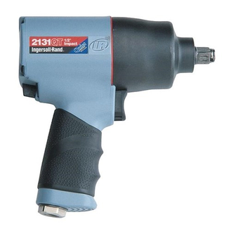
- Page 1 45481785 Edition 1 March 2007 Air Impact Wrench 2131 Series Maintenance Information Save These Instructions...
- Page 2 WARNING Always wear eye protection when operating or performing maintenance on this tool. Always turn off the air supply and disconnect the air supply hose before installing, removing or adjusting any accessory on this tool or before performing any maintenance on this tool. Note: When reading the instructions, refer to exploded diagrams in parts Information Manuals when applicable (see under Related Documentation for form numbers).
- Page 3 1. Secure the Inlet Bushing in a vise. Press in both tabs of the Inlet Retainer Clip (27) and pull upward on the Housing (19). This NOTICE will allow the Inlet Bushing to come free from the Handle of the To prevent damage to the Cylinder, do not tap or strike Cylinder on Housing.
- Page 4 REMOVAL OF FORWARD/ REVERSE BUTTONS REVERSE VALVE (Dwg. TPD1328) 2. Insert thumb into the front of the Housing and push down on the (Dwg. TPD1329) Reverse Valve so that it can be removed through the bottom of the handle. Refer to Dwg. TPD1329. NOTICE Do not try to remove the Reverse Valve by pushing upward.
- Page 5 NOTICE If the Reverse Valve is pushed up too far and becomes wedged, it will have to be pushed back down through the handle and re-inserted from the bottom of the handle. The Reverse Valve cannot be removed by pushing it up through the handle and REAR OF into the motor bore.
- Page 6 Assembly of the Impact Mechanism NOTICE When re-installing the Inlet Bushing Assembly (20), pull the Trigger (28) outward and make sure that the Reverse Button (4B) is depressed before snapping the Inlet Bushing Assembly back into the Housing. 3. Install the Inlet Bushing Assembly by pushing it into the hole in TOP HAMMER the Housing until you see and hear the tabs on Inlet Retainer Clip HALF- - ROUND...
-
Page 7: Troubleshooting Guide
FRONT OF NOTICE HOUSING Be sure that the flat on the bottom of the Hammer Case Gasket is installed in the corresponding flat in the Housing. If the Hammer Case Gasket is not installed correctly, the Air Wrench will not GASKET function properly. - Page 8 www.irtools.com © 2007 Ingersoll Rand Company...


Need help?
Do you have a question about the 2131 Series and is the answer not in the manual?
Questions and answers