Table of Contents
Advertisement
Quick Links
Installation Instructions
INSTALLATION BY A HVAC PROFESSIONAL IS RECOMMENDED
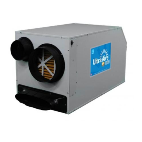
The Ultra-Aire XT105H is a whole house ventilating dehumidifier
that is integrated into the heating and cooling system to provide
the ultimate in comfort, health and property protection through:
• Dehumidification
• Fresh Air Ventilation (Optional)
• Air Filtration
HVAC Installer: Please Leave Manual for Homeowner
P/N: 4032240
Serial No.:
Sold by:
PATENTS:
D570,988
8,069,681
9,052,132
Install Date:
TS-902 5/19/16
Advertisement
Table of Contents
Troubleshooting

Related Manuals for Therma-Stor ultra-aire XT105H


Summary of Contents for Therma-Stor ultra-aire XT105H
-
Page 1: Installation Instructions
9,052,132 Installation Instructions INSTALLATION BY A HVAC PROFESSIONAL IS RECOMMENDED The Ultra-Aire XT105H is a whole house ventilating dehumidifier that is integrated into the heating and cooling system to provide the ultimate in comfort, health and property protection through: • Dehumidification •... -
Page 2: Table Of Contents
Service ..................21 Troubleshooting ................... 22 Warranty ..................24 Ultra-Aire is committed to manufacturing quality products. To maintain our standards, product specifications may change without notice. 4201 Lien Rd. Madison, WI 53704 1-800-533-7533 www.Thermastor.com | www.Ultra-Aire.com © 2015 Therma-Stor LLC... -
Page 3: Safety Instructions
THIS SYMBOL MEANS IMPORTANT INSTRUCTIONS. FAILURE TO HEED THEM CAN RESULT IN INJURY OR MATERIAL PROPERTY DAMAGE. Registrations The Ultra-Aire XT105H conforms to unified standard UL 60335-2-40 and CSA Standard C22.2 No. 92. WARNING! 120 VOLTS MAY CAUSE SERIOUS INJURY FROM ELECTRIC SHOCK. -
Page 4: Specifications
21 3/4" 28" Length: 41 1/2" 37 3/4" 42" Weight: 140 lbs. 139 lbs. 162 lbs. 1/2" FRONT BACK 3/4" 1/4" 1/4" 6" Diameter 10" Diameter 10" Diameter FRONT VIEW SIDE VIEW BACK VIEW Ultra-Aire XT105H Installation Instructions www.Ultra-Aire.com | 1-800-533-7533... -
Page 5: Optional Accessories
REMOVE COMPRESSOR SHIPPING TIE FROM THE UNIT. FAILURE TO REMOVE SHIPPING TIE WILL CAUSE EXCESS VIBRATION TO BE TRANSMITTED TO THE FRAME. Removal of Compressor Shipping Support The Ultra-Aire XT105H uses a compressor to power the refrigeration system. To protect the compressor and refrigeration system during shipping, a plastic tie wrap secures it to the unit’s frame. -
Page 6: Dehumidifier Set Up
• DO NOT place the dehumidifier directly on structural building members without vibration absorbers or unwanted noise may result. Place the Ultra-Aire XT105H on supports to raise the base of the unit. • A drain pan MUST be placed under the dehumidifier if installed above a living area or above an area where water leakage could cause damage. -
Page 7: Attaching Duct Collars
Adhere seal onto the back of the oval duct and mount the duct to the front of the dehumidifier using the screws provided. 6" Fresh Air Inlet (Optional) 10" Return Air Inlet 10" Supply Air Outlet Collars and hardware are SIDE VIEW FRONT VIEW located here. www.Ultra-Aire.com | 1-800-533-7533 Ultra-Aire XT105H Installation Instructions... -
Page 8: Electrical Requirements
Consult local electrical codes for further information. Ultra-Aire offers a variety of control devices for use with the Ultra-Aire XT105H. The control is to be located remotely from the dehumidifier and placed in the space to be conditioned. A low voltage (24 Volt) control MUST be used with the Ultra-Aire XT105H and MUST be connected with low voltage (18-22 gauge) thermostat wire. -
Page 9: Drain Installation
Install a drain pipe assembly utilizing 3/4" PVC pipe to transport the condensate to a drain. Pitch of drain should be 1" per 10'. An optional condensate pump kit is available for use with the Ultra-Aire XT105H and may be installed if lift is Drain Port required to dispose of condensate. -
Page 10: Ducting To Hvac Systems
Duct the supply of the unit to the air supply of the existing HVAC system. Connect an insulated duct from outside to the 6" collar of the Ultra-Aire XT105H to provide fresh make-up air. Adjust the damper in the duct to provide the desired amount of fresh air. -
Page 11: Recommended Hvac System Installations
(optional). • Duct the supply of the Ultra-Aire XT105H to the supply of the existing HVAC system with a backdraft damper. • If the existing system has multiple returns, instead of installing a dedicated return to the Ultra-Aire XT105H, it is possible to select one to disconnect from the existing HVAC system and use it for the dedicated Ultra-Aire XT105H return. -
Page 12: Alternative Hvac System Installations
• For basement and crawlspace installations, an optional tee can be installed on the Ultra-Aire Supply. Dedicated Ultra-Aire Return to HVAC Return Create a separate return for the Air Handler Fresh Air Intake Motorized Ultra-Aire XT105H in a central HVAC Supply (Optional) Damper HVAC Return area of the building. -
Page 13: Recommended Multiple Hvac Systems Installation
DUCTING TO HVAC SYSTEMS Recommended Multiple HVAC Systems Installation The Ultra-Aire XT105H can be installed on multiple HVAC systems. Dehumidified air will be provided to both HVAC systems for distribution throughout the structure. • Backdraft dampers are required in the supply ducts. -
Page 14: No Existing Ductwork Installation
DUCTING TO HVAC SYSTEMS No Existing Ductwork Installation When installing the Ultra-Aire XT105H in a structure that does not have a forced air HVAC system, a single return for the Ultra Aire XT105H should be installed in a central location. -
Page 15: Fresh Air Ventilation
Fresh air may be brought into the structure by connecting an insulated duct from outside the structure to the 6" inlet of the Ultra-Aire XT105H. A ventilation control is needed to program the time and frequency that the unit introduces outside air. The time and frequency of ventilation should be based on the size and occupancy of the residence. -
Page 16: Determine Ventilation Requirements
Number of Bedrooms Floor Area >7 < 1500 ft 1501 - 3000 3001 - 4500 4501 - 6000 6001 - 7500 > 7500 ft Table 4.1 from ASHRAE 62.2-2010 Record the required CFM ____________ Ultra-Aire XT105H Installation Instructions www.Ultra-Aire.com | 1-800-533-7533... -
Page 17: Controls
The control and the control wires leaving the Ultra-Aire XT105H are numbered and color-coded to prevent confusion. Depending on the control, some of the wires leaving the Ultra-Aire XT105H may not be used. For safety, the unconnected wires should be covered with wire nuts. Be sure to consult the electrical schematic in this manual or inside the access panel of the Ultra-Aire XT105H before making control connections. - Page 18 CONTROLS A low voltage control must be used with the Ultra-Aire XT105H. Five Color Coded Wires Control Operation Green (or brown) Fan control Blue Dehumidification (fan and compressor) control 24 VAC power transformer neutral side (common with white) White 24 VAC power transformer neutral side (common with red)
-
Page 19: Air Filtration
AIR FILTRATION The Ultra-Aire XT105H is equipped with a MERV-11 filter. An optional MERV-14 filter and filter housing is available at www.UltraAireFilters.com. The filter should be checked and replaced every three to six months. Operating the unit with a dirty filter will reduce dehumidifier capacity and efficiency. -
Page 20: Merv Rating Chart
Dust Mites Residential Sanding Dust <20% 65-70% Spray Paint Dust Electrostatic - Self charging Textile Fibers Window A/C Units woven panel filter. <20% <65% Carpet Fibers Table Data Source: United States Environmental Protection Agency Ultra-Aire XT105H Installation Instructions www.Ultra-Aire.com | 1-800-533-7533... -
Page 21: Service
Transformer Refrigerant Charging WARNING! SERVICING THE ULTRA-AIRE XT105H WITH ITS HIGH PRESSURE REFRIGERANT SYSTEM AND HIGH VOLTAGE CIRCUITRY PRESENTS A HEALTH HAZARD WHICH COULD RESULT IN DEATH, SERIOUS BODILY INJURY, AND/OR PROPERTY DAMAGE. SERVICE MUST BE PERFORMED BY A QUALIFIED SERVICE TECHNICIAN. -
Page 22: Troubleshooting
5. Dirty air filter(s) or air flow restricted. 9. If this test works, then the field control wiring is ok. 6. Defective fan or relay. 10. If the problem persists, then the control is most likely faulty. Ultra-Aire XT105H Installation Instructions www.Ultra-Aire.com | 1-800-533-7533... -
Page 23: Troubleshooting Procedure
7. Collecting the water removed in a 24 hour period 8. Defective compressor. will give a measurement of performance. 9. Restrictive ducting. www.Ultra-Aire.com | 1-800-533-7533 Ultra-Aire XT105H Installation Instructions... -
Page 24: Warranty
Product is included, abuse, lack of normal care, failure to follow written instructions, tampering, improper repair, or freezing, corrosion, acts of nature or other causes not arising out of defects in Therma-Stor’s workmanship or material. If a Product or Component is replaced while under warranty, the applicable limited warranty period shall not be extended beyond the original warranty time period. - Page 25 | 1-800-533-7533 Ultra-Aire XT105H Installation Instructions...
- Page 26 Ultra-Aire XT105H Installation Instructions www.Ultra-Aire.com | 1-800-533-7533...
- Page 27 | 1-800-533-7533 Ultra-Aire XT105H Installation Instructions...
- Page 28 1-800-533-7533 www.Ultra-Aire.com...
Need help?
Do you have a question about the ultra-aire XT105H and is the answer not in the manual?
Questions and answers