
Related Manuals for Toro 41177 Multi-Pro 1250


Summary of Contents for Toro 41177 Multi-Pro 1250
- Page 1 Form No. 3356-699 Rev B Multi-Pro 1250 Turf Sprayer Model No. 41177—Serial No. 270000001 and Up Register your product at www.Toro.com Original Instructions (EN)
-
Page 2: Table Of Contents
1. Safety alert symbol. others avoid injury and product damage. Although Toro designs and produces safe products, you are responsible for operating the product properly This manual uses two other words to highlight and safely. - Page 3 Vibration..........8 Checking the Air Intake Safety and Instructional Decals .... 8 Screen ....... 45 Setup ..............13 Servicing the Air Cleaner ....45 1 Installing the Anti-siphon Fill Servicing the Engine Oil ....46 Receptacle ......13 Changing the Spark Plugs....47 2 Installing the Spray Pro Fuel System Maintenance ......
-
Page 4: Safety
Safety Supervisor’s Responsibilities • Make sure that operators are thoroughly Improper use or maintenance by the operator or trained and familiar with the Operator’s Manual, Engine Manual, and all labels on the sprayer. owner can result in injury. To reduce the potential for injury, comply with these safety instructions •... -
Page 5: Before Operating
• Properly dispose of unused chemicals and • Be extremely careful when operating around chemical containers as instructed by the people. Always be aware of where bystanders chemical manufacturer and your local codes. might be and keep them away from the work area. - Page 6 • Failure to operate the sprayer safely may result 1. Stop the movement of the machine. in an accident, tip over of the sprayer, and 2. Place the range selector in Neutral and set serious injury or death. Drive carefully. To the parking brake.
-
Page 7: Maintenance
• Before servicing or making adjustments to • The Toro Company strongly recommends the machine, stop the engine, set the parking installing the optional ROPS Kit when brake, and remove the key from the ignition operating on hilly terrain. -
Page 8: Sound Pressure
Vibration could be dangerous. Altering this sprayer in any manner that may affect sprayer operation, This unit does not exceed a hand/arm vibration performance, durability, or its use, may result level of 2.5 m/s , based on measurements of in injury or death. Such use could void the identical machines per EN 1033. - Page 9 100-8470 1. Engine—stop 5. Neutral engine speed lock 2. Engine—run 6. Engage 3. Engine—start 7. On 4. Headlights 8. Off 100-8454 1. Read the Operator’s Manual for information on the transmission. 2. To start the engine, sit on the operator’s seat, press the brake, set the range selector to Neutral, turn the ignition key to Engine-start, set the range selector to the desired gear, release the brake and parking brake, and press the...
- Page 10 106-5016 1. Warning—read the Operator’s Manual. 2. Electric shock hazard, overhead power lines—stay away from overhead power lines. 3. Crushing hazard, boom—keep bystanders a safe distance from the machine. 93-0688 1. Warning—read the Operator’s Manual. 2. Caustic liquid/chemical burn and toxic gas inhalation hazards—wear hand, skin, eye, and respiratory protection.
- Page 11 110-5143 106-5051 1. Warning—read the Operator’s Manual. 1. Warning—read the Operator’s Manual; use fresh, clean water 2. Tipping Hazard—drive slowly over rough terrain and when for rst-aid washing. turning. 3. Falling and arm/leg injury hazards—do not carry passengers and keep arms and legs inside of the vehicle at all times. 4.
- Page 12 108-3252 1. Warning—read the 2. Torque lug nuts to 55-65 Operator’s Manual. ft-lb (75-88 N·m). 108-3699 1. 3o amp fuse, left boom 6. 10 amp fuse, headlights actuator 2. 3o amp fuse, right boom 7. 5 amp fuse, cruise control actuator 3.
-
Page 13: Setup
Setup Loose Parts Use the chart below to verify that all parts have been shipped. Step Description Qty. 90 degree tting Quick coupler Hose adapter Install the anti-siphon ll receptacle. Fill receptacle bracket Flange-head bolt, 5/16 x 3/4 inch Anti-siphon hose Spray Pro Monitor Spray Pro Decal Bracket... -
Page 14: Installing The Anti-Siphon Fill Receptacle
Step 3. Install the hose adapter into the quick coupler (Figure 3). 4. Lock the adapter into place by swinging the levers toward the adapter and then secure them with the hairpin cotters (Figure 3). Installing the Anti-siphon 5. Install the anti-siphon hose through the large Fill Receptacle opening on the bracket and onto the barbed end of the 90 degree elbow fitting (Figure 3). -
Page 15: Checking The Boom Hinge
2. Install the monitor bracket on the dash 6. Install the Spray Pro monitor over the carriage (Figure 5) using 2 flange-head bolts bolt heads (Figure 5) and tighten the knobs to (1/4 x 3/4 inch) and 2 flange nuts (1/4 inch). secure it. -
Page 16: Completing The Setup: Learning
Pre-delivery Inspection Sheet Procedure 1. Read the manuals. 2. View the Operator training material. 3. Complete the registration card and return to Toro. 4. Store the documentation in a safe place. Figure 8 1. Boom hinge spring 2. Jam nut 4. -
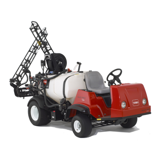
Page 17: Product Overview
Product Overview Figure 9 1. Left boom 4. Headlight 7. Chemical tank 10. Operator’s position 2. Right boom 5. Fresh water tank 8. Anti-Siphon Receptacle 3. Boom transport cable 6. Gas tank 9. Tank lid Figure 10 4. Pump 1. Pedals 7. -
Page 18: Controls
Controls Figure 11 1. Steering wheel 4. Choke 7. Parking brake 10. Voltmeter 2. Spray-Pro monitor 5. Sprayer controls 8. Master boom foot switch 11. Hour meter 3. Speed limiter 6. Rate lockout switch 9. Range Selector 12. Vehicle controls Accelerator Pedal Brake Pedal The accelerator pedal (Figure 12) gives you... - Page 19 smoothly. As soon as possible, push the control down to the Off position. A warm engine requires little or no choking. Range Selector The range selector, located to the left of the seat, has 5 positions: 3 forward speeds, Neutral, and Reverse (Figure 15).
- Page 20 Hour Meter The hour meter (Figure 15) indicates the total number of hours the engine has run. The hour meter starts to function whenever the key is turned to the Run position. Voltmeter The voltmeter (Figure 15) indicates the level of charge in the battery.
- Page 21 Pump Switch Rate Control Valve The pump switch is located on the control panel This valve, located behind the tank (Figure 18), to the right of the seat (Figure 17). Toggle this controls the amount of fluid that is routed to the switch forward to run the pump or rearward to booms by directing fluid flow to the booms or stop the pump.
- Page 22 Agitation Control Valve Pressure Gauge This valve is located on the right side of the tank The pressure gauge is located to the right of the (Figure 19). Turn the knob on the valve to the tank (Figure 19). This gauge shows the pressure 9 o’clock position to turn on the tank agitation of the fluid in the system in psi and kPa.
- Page 23 Spray Pro™ Monitor The monitor has an LCD screen that displays the data you select, a selection dial, and 4 buttons for The Spray Pro monitor displays and monitors calibrating the monitor (Figure 20). various system performance data such as vehicle speed and application rates.
-
Page 24: Specifications
Wheel base 62 inches (157 cm) • Decrease Optional Equipment Reduces values displayed on the screen during The Toro Company has optional equipment and calibration. accessories that you can purchase separately and • Increase install on your sprayer. Contact your Authorized... -
Page 25: Operation
Operation Check the Tire Pressure Check the tire pressure every 8 hours or daily Note: Determine the left and right sides of the to ensure proper levels. Fill the tires to 18 psi machine from the normal operating position. (124 kPa). Also, check the tires for wear or damage. Think Safety First Add Fuel Please carefully read all of the safety instructions... -
Page 26: Pre-Starting Checks
In certain conditions during fueling, static electricity can be released causing a spark which can ignite the gasoline vapors. A fire or explosion from gasoline can burn you and others and can damage property. • Always place gasoline containers on the ground away from your vehicle before filling. -
Page 27: Driving The Sprayer
before taking the sprayer out for the day. Your supervisor may want you to check other items on a daily basis, so ask what your responsibilities are. Driving the Sprayer Starting the Engine 1. Sit in the Operator’s seat, insert the key into the ignition switch, and rotate the key clockwise to the Run position. -
Page 28: Operating The Sprayer
optimum performance until several hours of is available in a formulation that would provide use has caused the brakes to become burnished increased life to the sprayer, use this alternative (broken-in). formulation. • Avoid racing the engine. As always, remember to clean your sprayer thoroughly after all applications. -
Page 29: Operating The Booms
Important: Verify that the proper 9. Turn the agitation control valve to the 9 o’clock application rate has been set prior to filling the position to start agitation in the tank. tank with chemicals. 10. Add the proper amount of chemical 1. -
Page 30: Spraying
movement, they should be immediately put back D. Return to the location where spraying is into the transport cradle. to begin. Important: The booms can be damaged by 6. Set the master boom switch to the On position to begin spraying. transporting them in any position other than the “X”... - Page 31 Figure 26 1. Rinse tank (for use with the optional rinse kit, 106-4842) 1. Stop the sprayer, set the parking brake, place the range selector in the Neutral position, and turn off the engine. The tank will drain to left side of the machine.
- Page 32 10. Allow all of the water in the tank to spray out though the nozzles. 11. Check the nozzles to ensure that they are all spraying correctly. 12. Set the master boom switch to the Off position, set the pump switch to the Off position, and stop the engine.
-
Page 33: Calibrating The Spray Pro
Calibrating the Spray Pro Monitor Figure 29 1. LCD screen 6. Application rate 11. Reset, calibration button 16. Select units 2. Selection dial 7. Distance 12. Calibrate, calibration button 17. Width 3. Total area 8. Sub Area 13. Decrease, calibration button 18. Speed calibration 4. - Page 34 Setting the Units of Measure 8. Compare the volume displayed on the monitor to the volume of water you put into the tank. The default setting for the units of measure is • If the volumes are the same, you do not US.
-
Page 35: Calibrating The Boom Bypass
8. Turn the selection dial to the Distance position. valves so that the pressure and application rate remains the same for all booms when you turn one 9. Press and hold the Reset calibration button or more booms off. until the display reads “0”. Note: The boom bypass valves must be 10. -
Page 36: Pump
recommended for nozzle spray pressures between 20 psi (1.3 bar) and 45 psi (3 bar). If different nozzle pressures are required, set pressure dampener at pressures indicated. Nozzle Dampener 40 psi/2.7 bar 12–14 psi/0.8–0.9 bar Transporting the Sprayer Figure 30 For moving the sprayer long distances, use a trailer. - Page 37 2. Put the range selector in the Neutral position and release the parking brake. 3. Tow the sprayer at less than 5 mph (8 kph).
-
Page 38: Maintenance
Maintenance Note: Determine the left and right sides of the machine from the normal operating position. Recommended Maintenance Schedule(s) Maintenance Service Maintenance Procedure Interval • Torque the wheel lug nuts. • Check the drive belt tension. After the rst 8 operating •... - Page 39 Toro Service Distributor). • Inspect the pressure dampener bladder and replace if necessary (see an Every 400 hours Authorized Toro Service Distributor). • Inspect the pump check valves and replace if necessary (see an Authorized Toro Service Distributor). • Change the pump drive gearbox uid.
-
Page 40: Daily Maintenance Checklist
Daily Maintenance Checklist Duplicate this page for routine use. Maintenance Check Item For the week of: Mon. Tues. Wed. Thurs. Fri. Sat. Sun. Check the brake and parking brake operation. Check the gear shift/neutral operation. Check the fuel level. Check the engine oil level. Check the transaxle oil level. -
Page 41: Premaintenance Procedures
If you leave the key in the ignition switch, someone could accidently start the engine and seriously injure you or other bystanders. Remove the key from the ignition and disconnect the wire(s) from the spark plug(s) before you do any maintenance. Set the wire(s) aside so that it does not accidentally contact the spark plug(s). -
Page 42: Lubrication
Figure 34 1. Front jacking points The jacking point at the rear of the sprayer is on the rear frame support, between the angle welds (Figure 35). Figure 36 At the wheels, three on each side 1. Grease point Figure 35 1. -
Page 43: Greasing The Boom Hinges
Figure 38 Figure 41 Pump drive, four, one each side Pump (Do not over grease) 1. Grease point 1. Grease point Figure 42 Figure 39 1. Grease point Drive axel at engine, ve, one each side and slip joint 1. Grease point Greasing the Boom Hinges Important: If the boom hinge is washed with water, all water and debris must be... -
Page 44: Greasing The Actuator Rod
Figure 43 Figure 44 Right boom 1. Actuator 4. Cotter 1. Grease tting 5. Pin 2. Actuator rod 3. Boom pivot pin housing 3. Wipe off excess grease. 3. Lift up on the boom and remove the pin 4. Repeat the procedure for each boom pivot. (Figure 44). -
Page 45: Engine Maintenance
6. Raise the boom to align the pivot with the actuator rod. While holding the boom, insert the pin through both boom pivot and actuator rod (Figure 44). 7. With the pin in place, release the boom and secure the pin with the cotter removed previously. -
Page 46: Servicing The Engine Oil
Inspect the paper element for tears, an oily film, damage to the rubber seal, excessive dirt, or other Toro Premium Engine Oil is available from your damage (Figure 48). If any of these conditions distributor in either 15W40 or 10W30 viscosity. -
Page 47: Changing The Spark Plugs
Components under the seat will be hot if the sprayer has been running. If you touch hot components you may be burned. Allow the sprayer to cool before performing maintenance or touching components under the hood. 4. Place a pan below the oil drain. 5. -
Page 48: Fuel System Maintenance
Installing the Spark Plugs 4. Clean around the spark plugs to prevent dirt from falling into the engine and potentially 1. Install the spark plugs and metal washers. causing damage. 2. Tighten the spark plugs to 18 to 22 ft-lb (24.4 5. -
Page 49: Electrical System Maintenance
Electrical System Voltage: 12 volt with 280 cold cranking Amps @ 0° F Maintenance Removing the Battery Replacing the Fuses 1. Position the sprayer on a level surface, set the parking brake, stop the pump, stop the engine, There are 2 fuse blocks and 1 empty slot in the and remove the ignition key. -
Page 50: Charging The Battery
distilled water; refer to Adding Water to the Battery. Battery terminals or metal tools could short against metal sprayer components causing sparks. Sparks can cause the Battery electrolyte contains sulfuric acid battery gasses to explode, resulting in which is a deadly poison and causes personal injury. -
Page 51: Drive System Maintenance
• Always remove the key from the 5. Lubricate the moving parts in the areas circled in Figure 59 using Toro Dry Lubricant Spray, ignition before getting off of the sprayer. available through your Authorized Toro Dealer or Distributor. -
Page 52: Inspecting The Wheels/Tires
measurement of the front tires at axle height. Use the same fixture or alignment gauge to accurately measure the front of the front tires at axle height (Figure 60). The front of the tires should be 0 to 1/4 inch (0 to 6 mm) closer than the back side of the front tires. -
Page 53: Brake Maintenance
Brake Maintenance Checking the Brake Fluid The brake fluid reservoir is shipped from the factory filled with DOT 3 brake fluid. Check the level before starting the engine each day. Figure 63 1. Full line 3. If the fluid level is low, clean the area around the reservoir cap, remove the cap, and fill the reservoir to the proper level. -
Page 54: Belt Maintenance
Figure 65 1. Drive belt 3. Secondary clutch 2. Primary clutch Figure 64 1. Parking brake lever 3. Set screw Replacing the Drive Belt 2. Knob 1. Rotate and route the belt over the secondary clutch (Figure 65). 2. Rotate the knob until a force of 35-45 lb is required to actuate lever. -
Page 55: Hydraulic System Maintenance
Figure 67 1. Dipstick 2. Fill hole Figure 66 1. Steering pump belt 3. Steering pump mounting Important: Be very careful not to get bolts 2. Steering pump dirt or other contaminants into the opening when checking the transmission oil. 3. -
Page 56: Replacing The Hydraulic Filter
Replacing the Hydraulic Filter Initially, replace the hydraulic filter after 8 operating hours, thereafter, replace filter every 800 hours. Use the Toro replacement filter (Part No. 54-0110). Important: Use of any other filter may void the warranty on some components. -
Page 57: Spray System Maintenance
Replace any hoses and fittings if damaged. Pump Maintenance Inspecting the Pump Every 400 hours and/or yearly, have an Authorized Toro Service Distributor check following internal Figure 71 pump components for damage: 1. Pump drive gearbox 3. Drain plug •... -
Page 58: Emergency Manual Operation
0.085-0.100 inch (2.16-2.54 mm), you may wish to bleed the air from the hydraulic oil. Refer to the Service Manual for instructions on how to bleed air from the actuators or contact an Authorized Toro Service Distributor. Emergency Manual Operation of the Boom Actuators Note: Determine the left and right sides of the machine from the normal operating position. -
Page 59: Cleaning
Figure 73 1. Pivot pin 4. Nylon bushing 2. Bolt 5. Pivot bracket 3. Nut Figure 74 1. Retaining cap 3. Flowmeter body 4. Remove the boom and pivot bracket assembly 2. Paddle wheel assembly from the center frame to access the nylon bushings. - Page 60 Figure 75 1. Suction strainer 2. Disconnect the hose from the tank. 3. Pull the strainer out of the hole. 4. Clean the strainer with clean running water. 5. Replace the strainer, seating it fully into the hole. 6. Connect the hose to the top of the tank and secure it with the retainer.
-
Page 61: Storage
Storage use an alcohol based stabilizer (ethanol or methanol). Note: A fuel stabilizer/conditioner is 1. Position the sprayer on a level surface, set the parking brake, stop the pump, stop the engine, most effective when mixed with fresh and remove the ignition key. gasoline and used at all times. - Page 62 17. Check and tighten all bolts, nuts, and screws. Repair or replace any part that is damaged. 18. Check the condition of all spray hoses, replacing any that are damaged or worn. 19. Tighten all hose fittings. 20. Paint all scratched or bare metal surfaces. Paint is available from your Authorized Service Dealer.
-
Page 63: Troubleshooting
Troubleshooting Troubleshooting the Engine and Vehicle Problem Possible Cause Corrective Action The starter does not crank. 1. The range selector is in a 1. Press the brake pedal and gear other than Neutral. move the range selector to the Neutral position. 2. - Page 64 Problem Possible Cause Corrective Action The engine starts, but does 1. The fuel tank vent is 1. Replace the fuel cap. not keep running. restricted. 2. Dirt or water in the fuel 2. Drain and ush the fuel system. system; add fresh fuel. 3.
- Page 65 Problem Possible Cause Corrective Action The engine overheats. 1. The crankcase oil level is 1. Fill or drain to the full incorrect. mark. 2. Excessive loading. 2. Reduce load; use lower ground speed. 3. The air intake screens are 3. Clean with every use. dirty.
- Page 66 Problem Possible Cause Corrective Action The machine will not 1. The range selector is in 1. Press the brake and shift operate in either direction. the Neutral position. the range selector into a gear. 2. The parking brake was 2. Release the parking brake not released or the or check the linkage.
- Page 67 Problem Possible Cause Corrective Action A boom valve is leaking 1. An O-ring is deteriorated. 1. Stop the spray system and pump and turn off the sprayer. Disassemble the valve and replace the O-rings. A pressure drop occurs 1. The boom bypass valve 1.
- Page 68 Problem Possible Cause Corrective Action The Area is inaccurate. 1. The sprayer width is not 1. Check and set the correctly entered. appropriate Width in the calibration mode. 2. The speed sensor is not 2. Calibrate the speed calibrated correctly. sensor.
-
Page 69: Schematics
Schematics Electrical, vehicle (Rev. B) - Page 70 Electrical, spray system (Rev. A)
- Page 71 Hydraulic (Rev. A)
- Page 72 Flow Diagram (Rev. A)
- Page 75 The use of any add-on or modied parts will be grounds for disallowing a warranty claim made in accordance with this article. The Toro® Company will not be liable under this Article to warrant failures of warranted parts caused by the use of an add-on or modied part.
- Page 76 (Dealer) to obtain guarantee policies for your country, province, or state. If for any reason you are dissatised with your Distributor’s service or have difculty obtaining guarantee information, contact the Toro importer. If all other remedies fail, you may contact us at Toro Warranty Company.
Need help?
Do you have a question about the 41177 Multi-Pro 1250 and is the answer not in the manual?
Questions and answers