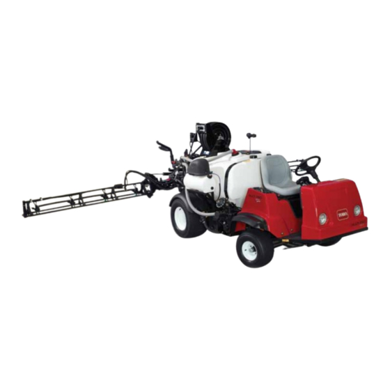
Toro Multi-Pro 1250 Operator's Manual
Turf sprayer
Hide thumbs
Also See for Multi-Pro 1250:
- Operator's manual (72 pages) ,
- Service bulletin (3 pages) ,
- Operator's manual (72 pages)
Table of Contents

Related Manuals for Toro Multi-Pro 1250


Summary of Contents for Toro Multi-Pro 1250
- Page 1 Form No. 3365-105 Rev B Multi-Pro ® 1250 Turf Sprayer Model No. 41197—Serial No. 310000001 and Up G013629 To register your product or download an Operator's Manual or Parts Catalog at no charge, go to www.Toro.com. Original Instructions (EN)
-
Page 2: Table Of Contents
Although Toro designs and produces safe Introduction..............2 products, you are responsible for operating the product Safety ................4 properly and safely. You may contact Toro directly at Safe Operating Practices ........4 www.Toro.com for product and accessory information, Chemical Safety............ 4 help finding a dealer, or to register your product. - Page 3 Safety and Instructional Decals ......8 Adjusting the Parking Brake........ 50 Setup................13 Belt Maintenance............ 50 1 Installing the Anti-siphon Fill Servicing the Drive Belt ........50 Receptacle ............14 Adjusting the Steering Pump Belt......50 2 Installing the Spray Pro Monitor....... 14 Hydraulic System Maintenance .......
-
Page 4: Safety
Chemical Safety Safety WARNING Improper use or maintenance by the operator or owner can result in injury. To reduce the potential for injury, Chemical substances used in the spray system may comply with these safety instructions and always pay be hazardous and toxic to you, bystanders, animals, attention to the safety alert symbol, which means plants, soils or other property. -
Page 5: Before Operating
Before Operating – Use an approved gasoline container. – Do not remove the cap from the fuel tank when • Operate the machine only after reading and the engine is hot or running. understanding the contents of this manual. – Do not smoke while handling gasoline. •... - Page 6 4. Remove the ignition key. cause the sprayer to overturn. Important: Do not park the machine on an • The Toro Company strongly recommends installing incline. the optional ROPS Kit when operating on hilly • Lightning can cause severe injury or death. If terrain.
-
Page 7: Maintenance
Measured values were determined according to the • Do not adjust the ground speed governor. To procedures outlined in EN 1032. ensure safety and accuracy, have an Authorized Toro Distributor check the ground speed. • Keep your body and hands away from pin hole leaks or nozzles that eject high pressure fluid. -
Page 8: Safety And Instructional Decals
Safety and Instructional Decals Safety decals and instructions are easily visible to the operator and are located near any area of potential danger. Replace any decal that is damaged or lost. 104-7628 1. Read the Operator’s Manual. 100-8458 1. Machine speed 2. - Page 9 100-8470 1. Engine—stop 5. Neutral engine speed lock 2. Engine—run 6. Engage 3. Engine—start 7. On 4. Headlights 8. Off 107-8621 1. Agitation on 3. Agitation off 2. Continuous variable setting 100-8489 1. Left boom 11. Decrease 2. Center boom 12.
- Page 10 106-5016 1. Warning—read the Operator’s Manual. 2. Electric shock hazard, overhead power lines—stay away from overhead power lines. 3. Crushing hazard, boom—keep bystanders a safe distance from the machine. 110-5143 1. Warning—read the Operator’s Manual. 2. Tipping Hazard—drive slowly over rough terrain and when turning.
- Page 11 108-3252 1. Warning—read the 2. Torque lug nuts to 55-65 Operator’s Manual. ft-lb (75-88 N·m). 106-5051 1. Warning—read the Operator’s Manual; use fresh, clean water for first-aid washing. 108-3699 1. 30 amp fuse, left boom 6. 10 amp fuse, headlights actuator 108-3307 2.
- Page 12 104-8939 1. Engine oil level (dipstick) 5. Hydraulic strainer 9. Fuel, unleaded only 13. Grease 2. Engine oil filter 6. Gear box fluid level 10. Fuel filter 14. Tire pressure 3. Transaxle/hydraulic fluid 7. Brake fluid 11. Battery 15. Read the instructions level (dipstick) before servicing or performing maintenance.
-
Page 13: Setup
Important: To use the sprayer, you must obtain and install a boom kit and nozzles . Contact your Authorized Toro Distributor for information on the available boom kits and accessories. After you install your booms and nozzles and before using the sprayer for the first time, adjust the boom bypass valves so that the pressure and application rate remains the same for all booms when you turn one or more booms off. -
Page 14: Installing The Anti-Siphon Fill Receptacle
4. Lock the adapter into place by swinging the levers toward the adapter and then secure them with the hairpin cotters (Figure 3). 5. Install the anti-siphon hose through the large Installing the Anti-siphon Fill opening on the bracket and onto the barbed end of the 90 degree elbow fitting (Figure 3). -
Page 15: Completing The Setup: Learning More About Your Product
4. Remove the large grommet from the hole in the dash 2. View the Operator training material. and thread the cables on the monitor through the 3. Complete the registration card and return to Toro. grommet and the dash. 4. Store the documentation in a safe place. -
Page 16: Product Overview
Product Overview G013630 Figure 8 1. Operator’s position 3. Fresh water tank 5. Chemical tank 7. Tank lid 2. Headlight 4. Fuel tank 6. Anti-Siphon Receptacle G013631 Figure 9 1. Pedals 3. Chemical tank 5. Battery 7. Agitation control valve 2. -
Page 17: Controls
Controls Figure 10 1. Steering wheel 4. Choke 7. Parking brake 10. Voltmeter 2. Spray-Pro monitor 5. Sprayer controls 8. Master boom foot switch 11. Hour meter 3. Speed limiter 6. Rate lockout switch 9. Range Selector 12. Vehicle controls CAUTION Accelerator Pedal Brakes can become worn or can be adjusted... - Page 18 Range Selector The range selector, located to the left of the seat, has 5 positions: 3 forward speeds, Neutral, and Reverse (Figure 14). The engine will start only when the range selector is in the Neutral position. You must also fully press the brake with the sprayer stopped to change ranges.
- Page 19 Voltmeter Boom Switches The voltmeter (Figure 14) indicates the level of charge The boom switches are located at the front of the in the battery. When the battery is fully charged, the control panel to the right of the seat (Figure 16). Toggle voltmeter will read in the center of the dial when the each switch forward to turn the corresponding boom key is in the Run position with the engine off.
- Page 20 Rate Lockout Key Switch Flowmeter The rate lockout key switch is located on the control The flowmeter measures the flow rate of the fluid for panel to the right of the seat (Figure 16). Turn the key use by the Spray Pro™ system (Figure 17). counterclockwise to the locked position to disable the application rate switch, thereby keeping anyone from Boom Valves...
- Page 21 Pressure Gauge The pressure gauge is located to the right of the tank (Figure 18). This gauge shows the pressure of the fluid in the system in psi and kPa. Use the gauge to adjust the by-pass valves whenever you change nozzles. Anti-siphon Fill Receptacle To the front of the tank cover is a hose receptacle with a threaded fitting, a 90 degree barbed fitting, and a short...
- Page 22 Spray Pro™ Monitor The monitor has an LCD screen that displays the data you select, a selection dial, and 4 buttons for calibrating The Spray Pro monitor displays and monitors various the monitor (Figure 19). system performance data such as vehicle speed and application rates.
-
Page 23: Specifications
Wheel base 62 inches (157 cm) calibration. Optional Equipment Calibration Settings The Toro Company has optional equipment and accessories that you can purchase separately and install • Boom Width on your sprayer. Contact your Authorized Service • Units of Measure Dealer for a complete list of optional equipment that is •... -
Page 24: Operation
Check the Tire Pressure Operation Check the tire pressure every 8 hours or daily to ensure Note: Determine the left and right sides of the proper levels. Fill the tires to 18 psi (124 kPa). Also, machine from the normal operating position. check the tires for wear or damage. -
Page 25: Pre-Starting Checks
DANGER In certain conditions during fueling, static electricity can be released causing a spark which can ignite the gasoline vapors. A fire or explosion from gasoline can burn you and others and can damage property. • Always place gasoline containers on the ground away from your vehicle before filling. -
Page 26: Driving The Sprayer
Driving the Sprayer Starting the Engine 1. Sit in the Operator’s seat, insert the key into the ignition switch, and rotate the key clockwise to the Run position. 2. Press the brake and move the range selector to the Neutral position. 3. -
Page 27: Operating The Sprayer
For the following section to apply, you must obtain and install a boom kit and nozzles. Contact your • Keep chemicals away from your skin. Authorized Toro Distributor for information on the Should contact occur, wash the affected area available boom kits and accessories. After you install thoroughly with soap and clean water. -
Page 28: Filling The Spray Tank
Contact of the cover counterclockwise and swing it open. your Authorized Toro Distributor for information on You can remove the strainer inside for cleaning. To the available boom kits and accessories. After you... -
Page 29: Spraying
The boom lift switches on the sprayer control panel brake, press the accelerator pedal to the floor, turn allows you to move the booms between transport on the pump, and turn the neutral engine speed position and spray position without leaving the lock On. -
Page 30: Cleaning The Sprayer
range of the nozzles or there is a problem with the spray system. Cleaning the Sprayer Important: You must always empty and clean the sprayer immediately after each use. Failure to do so may cause the chemicals to dry or thicken in the g0131 lines, clogging the pump and other components. - Page 31 8. Set the pump switch to the On position and use the application rate switch to increase the pressure to a high setting. 9. Set the master boom switch and boom control switches to the On positions to begin spraying. 10.
-
Page 32: Calibrating The Spray Pro Monitor
Calibrating the Spray Pro Monitor Figure 28 1. LCD screen 6. Application rate 11. Reset, calibration button 16. Select units 2. Selection dial 7. Sub Area 12. Calibrate, calibration button 17. Width 3. Total area 8. Distance 13. Decrease, calibration button 18. Speed calibration 14. - Page 33 1. Stop the sprayer and set the parking brake. The display will alternate between the total volume reading (“HOLD” shown) and the flow calibration 2. Set the master boom switch to the Off position. value (“CAL HOLD” shown). The monitor displays “HOLD”. 10.
-
Page 34: Calibrating The Boom Bypass Valves
14. With the selection dial set to the Distance position, for the nozzles you installed on the booms (typically press and hold the Calibrate button until the 40 psi/2.75 bar). monitor displays “CAL HOLD” and the red light 10. Record the reading on the pressure gauge. on the monitor illuminates. -
Page 35: Transporting The Sprayer
Figure 32 1. Tie down points The rear tie-down points are two steel loops under the Figure 30 back of the frame just in front of the adjustable boom frame. 1. Pump 3. Pressure dampener 2. Grease fitting Towing the Sprayer Adjusting the Air Pressure in In case of an emergency, the sprayer can be towed for a short distance. -
Page 36: Maintenance
Every 400 hours • Inspect the pressure dampener bladder and replace if necessary. (see an Authorized Toro Service Distributor) • Inspect the pump check valves and replace if necessary. (see an Authorized Toro Service Distributor) • Change the pump drive gearbox fluid. -
Page 37: Daily Maintenance Checklist
Daily Maintenance Checklist Duplicate this page for routine use. Maintenance Check Item For the week of: Mon. Tues. Wed. Thurs. Fri. Sat. Sun. Check the brake and parking brake operation. Check the gear shift/neutral operation. Check the fuel level. Check the engine oil level. Check the transaxle oil level. -
Page 38: Premaintenance Procedures
CAUTION If you leave the key in the ignition switch, someone could accidently start the engine and seriously injure you or other bystanders. Remove the key from the ignition and disconnect the wire(s) from the spark plug(s) before you do any maintenance. -
Page 39: Lubrication
Lubrication Greasing the Sprayer Service Interval: Every 50 hours—Lubricate the pump. Every 100 hours/Yearly (whichever comes first)—Lubricate all grease fittings. Figure 35 Grease Type: No. 2 General Purpose Lithium Base 1. Rear jacking points Grease 1. Wipe the grease fitting clean so that foreign matter cannot be forced into the bearing or bushing. - Page 40 Figure 38 Steering rods 1. Grease point Figure 36 Pump (Do not over grease) 1. Grease point Figure 39 Pump drive, four, one each side 1. Grease point Figure 37 At the wheels, three on each side 1. Grease point Figure 40 Drive axel at engine, five, one each side and slip joint 1.
-
Page 41: Engine Maintenance
Engine Maintenance Checking the Air Intake Screen Service Interval: Before each use or daily—Clean the engine rotating screen. Every 100 hours—Clean the engine rotating screen (more often in dusty, dirty conditions). Figure 41 Drive axel at transmission Check and clean as necessary the air intake screen on the front of the engine before each use or daily. -
Page 42: Servicing The Engine Oil
Checking the Paper Element • Alternate oil: SAE 5W30 (below 32 degrees F) Service Interval: Every 100 hours/Yearly (whichever Toro Premium Engine Oil is available from your comes first)—Replace the paper air distributor in either 5W30 or 10W30 viscosity. See the cleaner element (more often in dusty, Parts Catalog for part numbers. - Page 43 2. Remove the dipstick and wipe it with a clean rag (Figure 46). Insert the dipstick into the tube and make sure it is seated fully. Remove the dipstick and check the oil level. Figure 47 1. Oil drain plug 6.
-
Page 44: Changing The Spark Plugs
contacts the filter adapter, then tighten the filter an If you see a light brown or gray coating on the additional 1/2 turn (Figure 48). insulator, the engine is operating properly. A black coating on the insulator usually means the air cleaner 6. -
Page 45: Fuel System Maintenance
Fuel System from the machine and pour the fuel out of the tank fill spout into the fuel container. Maintenance Note: If you remove the fuel tank, you will need to remove the fuel and return hoses from the tank Replacing the Fuel Filter before removing the tank. -
Page 46: Electrical System Maintenance
Removing the Battery Electrical System 1. Position the sprayer on a level surface, set the parking Maintenance brake, stop the pump, stop the engine, and remove the ignition key. Fuses 2. Loosen the knobs on the sides of the battery box and remove the battery cover (Figure 53). - Page 47 WARNING DANGER Battery terminals or metal tools could short Battery electrolyte contains sulfuric acid which against metal sprayer components causing is a deadly poison and causes severe burns. sparks. Sparks can cause the battery gasses to • Do not drink electrolyte or allow it to contact explode, resulting in personal injury.
-
Page 48: Drive System Maintenance
Drive System it on the shelf or on the machine. Leave the cables disconnected if it is stored on the machine. Store the Maintenance battery in a cool atmosphere to avoid quick deterioration of the charge in the battery. To prevent the battery from freezing, make sure it is fully charged. -
Page 49: Brake Maintenance
Brake Maintenance Checking the Brake Fluid The brake fluid reservoir is shipped from the factory filled with DOT 3 brake fluid. Check the level before starting the engine each day. Figure 54 1. Tire center line-back 4. Fixture 5. Axle center line distance 2. -
Page 50: Inspecting The Brakes
Inspecting the Brakes Belt Maintenance Service Interval: Every 100 hours Servicing the Drive Belt The brakes are a critical safety component of the sprayer. Inspect them as follows: Checking the Drive Belt • Inspect the brake shoes for wear or damage. If the Service Interval: After the first 8 hours lining (brake pad) thickness is less than 1/16 inch Every 200 hours... -
Page 51: Hydraulic System Maintenance
Hydraulic System Maintenance Checking the Transaxle/Hydraulic Fluid Service Interval: Every 200 hours 1. Position the sprayer on a level surface, set the parking brake, stop the pump, stop the engine, and remove the ignition key. 2. Remove the transaxle dipstick and wipe it with a clean rag (Figure 61). -
Page 52: Replacing The Hydraulic Filter
Service Interval: After the first 8 hours Every 800 hours/Yearly (whichever comes first) Use the Toro replacement filter (Part No. 54-0110). Important: Use of any other filter may void the warranty on some components. 1. Position the sprayer on a level surface, set the parking... -
Page 53: Spray System Maintenance
Warranty associated with this machine. • Before working on a spray system make sure the Have an Authorized Toro Service Distributor check system has been triple rinsed and neutralized following internal pump components for damage: according to the recommendations of the chemical manufacturer(s). - Page 54 4. Install and tighten the drain plug when the fluid stops draining. 5. Add approximately 1 quart (1 L) of Mobil SHC 634 Synthetic Lubricant to the fill tube. Important: Use only Mobil SHC 634 Synthetic Lubricant or equivalent synthetic fluid in the gear box.
-
Page 55: Cleaning
Cleaning 1. Remove the retainer from the red fitting attached to the large hose on the top of the tank. Cleaning the Flowmeter Service Interval: Every 200 hours/Yearly (whichever comes first) (More often when using wettable powders) 1. Thoroughly rinse and drain the entire spraying system. -
Page 56: Storage
Storage G. Dispose of fuel properly. Recycle as per local codes. 1. Position the sprayer on a level surface, set the parking Important: Do not store brake, stop the pump, stop the engine, and remove stabilizer/conditioned gasoline over 90 the ignition key. days 2. -
Page 57: Troubleshooting
Troubleshooting Troubleshooting the Engine and Vehicle Problem Possible Cause Corrective Action The starter does not crank. 1. The range selector is in a gear other 1. Press the brake pedal and move the than Neutral. range selector to the Neutral position. 2. - Page 58 Problem Possible Cause Corrective Action The engine will not idle. 1. The fuel tank vent is restricted. 1. Replace the fuel cap. 2. Dirt, water, or stale fuel is in the fuel 2. Drain and flush the fuel system; add system.
- Page 59 Troubleshooting the Spray System Problem Possible Cause Corrective Action A boom section does not spray. 1. The electrical connection on the boom 1. Turn the valve off manually. Disconnect valve is dirty or disconnected. the electrical connector on the valve and clean all leads, then reconnect it.
- Page 60 Problem Possible Cause Corrective Action The Distance is inaccurate. 1. The speed sensor is not calibrated 1. Calibrate the speed sensor. correctly. 2. The speed sensor is damaged. 2. Contact your Authorized Service Dealer. The monitor does not display Application 1.
-
Page 61: Schematics
Schematics Electrical, vehicle (Rev. B) - Page 62 Electrical, spray system (Rev. A)
- Page 63 Hydraulic (Rev. A)
- Page 64 G0131 Flow Diagram (Rev. A)
- Page 65 Notes:...
- Page 66 Notes:...
- Page 67 Notes:...
- Page 68 Countries Other than the United States or Canada Customers who have purchased Toro products exported from the United States or Canada should contact their Toro Distributor (Dealer) to obtain guarantee policies for your country, province, or state. If for any reason you are dissatisfied with your Distributor’s service or have difficulty obtaining guarantee information, contact the Toro importer.
Need help?
Do you have a question about the Multi-Pro 1250 and is the answer not in the manual?
Questions and answers