Table of Contents
Advertisement
Advertisement
Table of Contents

Related Manuals for Honda BF250A


Summary of Contents for Honda BF250A
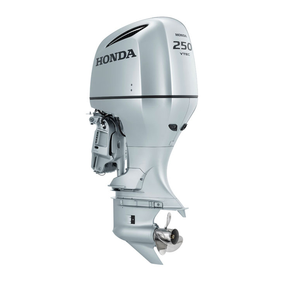
- Page 1 BF250A OWNER'S MANUAL Original instructions C Honda Motor Co., Ltd. 2012...
- Page 2 Thank you for purchasing a Honda Throughout this manual, you will see If a problem should arise, or if you Outboard Motor. safety messages proceeded by the have any questions about the following words and symbols. Here’s Outboard Motor, consult an...
- Page 3 Transom Height (25.0 in) 762 mm (30.0 in) Standard Rotating Propeller Shaft Counterrotating Propeller Shaft BF250A is provided with the following types TYPE CODE according to the shaft length and the rotating Example direction of the propeller shaft. Destination D: General Export, U: Europe...
- Page 4 The remote control type is classified FRAME SERIAL NUMBER ENGINE SERIAL NUMBER into the following three categories according to the control box position. Side-mount type: R1 type Panel-mount type: R2 type Top-mount type: R3 type Check the type of your outboard motor and read this Owner’s Manual thoroughly before operation.
-
Page 5: Table Of Contents
CONTENTS 1. SAFETY ...................6 Digital Speedometer (optional equipment) ......... 29 Interface Coupler ................ 30 SAFETY INFORMATION ............6 5. INSTALLATION ................31 2. SAFETY LABEL LOCATIONS ............8 Transom Height ................31 3. COMPONENT IDENTIFICATION ..........10 Location ..................32 4. CONTROLS AND FEATURES ............15 Installation Height .............. - Page 6 Shallow Water Operation ............74 9. STOPPING THE ENGINE .............75 16. SPECIFICATIONS ..............112 Emergency Engine Stop ..............75 17. MAJOR Honda DISTRIBUTOR ADDRESSES ....... 114 Normal Engine Stop ..............75 18. ‘‘EC DECLARATION OF CONFORMITY’’ 10. TRANSPORTING ................77 CONTENT OUTLINE ............117 Fuel Line Disconnection .............77...
-
Page 7: Safety
Do not shift to the reverse manufacturer’s power position suddenly at high recommendation, and be sure that engine speed. • Honda outboard motor is the outboard motor is properly designed to give safe and • Gasoline is harmful or fatal if mounted. - Page 8 SAFETY • Do not operate the outboard motor The engine and exhaust system Carbon Monoxide Poisoning without the engine cover. Exposed become very hot during operation and Hazard moving parts can cause injury. remain hot for a while after stopping. Exhaust contains poisonous carbon •...
-
Page 9: Safety Label Locations
They warn you of potential hazards that can cause serious injury. Read the labels and safety notes and precautions described in this manual carefully. If a label comes off or becomes hard to read, contact your Honda outboard motor dealer for a replacement. READ OWNER’S MANUAL READ OWNER’S MANUAL... - Page 10 SAFETY LABEL LOCATIONS CE mark location [U type only] CE MARK Year code Dry mass (weight) (with propeller, without battery cable) Name and address of authorized representative Manufacturer and address Year code Year of manufacture 2012 2013 2014 2015 2016 2017 2018...
-
Page 11: Component Identification
3. COMPONENT IDENTIFICATION COOLING WATER ENGINE COVER CHECK HOLE POWER TILT SWITCH ENGINE COVER LATCH TILT LOCK LEVER FLUSH PLUG CONNECTOR IDLE PORT FRAME SERIAL STERN BRACKET NUMBER ENGINE OIL DRAIN BOLT MANUAL RELIEF (inside cover) VALVE ANODE ANODE ANTICAVITATION PLATE ANODE EXHAUST PORT/ WATER OUTLET PORT... - Page 12 COMPONENT IDENTIFICATION OIL FILLER CAP SPARK PLUGS (under coil) SPARK PLUGS (under coil) OIL LEVEL DIPSTICK JUNCTION BOX (FUSES) WATER SEPARATOR FUEL FILTER INTERFACE COUPLER (inside strainer cup)
- Page 13 COMPONENT IDENTIFICATION REMOTE CONTROL BOX (optional equipment) SIDE-MOUNT TYPE (R1 type) PANEL-MOUNT TYPE (R2 type) REMOTE CONTROL REMOTE CONTROL NEUTRAL RELEASE LEVER LEVER LEVER POWER TRIM/TILT INDICATORS SWITCH (Oil pressure, Overheat, ACG, PGM-FI) SPARE NEUTRAL RELEASE EMERGENCY STOP LEVER FAST IDLE SWITCH CLIP LEVER POWER TRIM/TILT...
- Page 14 COMPONENT IDENTIFICATION TOP-MOUNT TYPE (R3 type) (SINGLE OUTBOARD MOTOR TYPE) (DUAL OUTBOARD MOTOR TYPE) REMOTE CONTROL LEVER REMOTE CONTROL LEVERS POWER TRIM/TILT SWITCH (RIGHT) POWER TRIM/TILT SWITCH POWER TRIM/TILT SWITCH (LEFT) FAST IDLE BUTTON FAST IDLE BUTTON SWITCH PANEL (optional equipment) (for TOP-MOUNT DUAL type) (PANEL-MOUNT, TOP-MOUNT) INDICATORS...
- Page 15 COMPONENT IDENTIFICATION (Common) TRIMMETER (Optional equipment) TACHOMETER (Optional equipment) DIGITAL SPEEDOMETER (Optional equipment) DIGITAL TACHOMETER (Optional equipment)
-
Page 16: Controls And Features
4. CONTROLS AND FEATURES Remote Control Lever (R1 type) NEUTRAL 30° REMOTE CONTROL LEVER 30° FORWARD REVERSE SHIFT SHIFT FORWARD MINIMUM NEUTRAL MINIMUM THROTTLE OPENING THROTTLE OPENING REVERSE MAXIMUM MAXIMUM NEUTRAL REMOTE CONTROL RELEASE LEVER LEVER FORWARD: REVERSE: Shifting gear into forward, reverse, or Moving the lever to the FORWARD Moving the lever to the REVERSE neutral and the engine speed... -
Page 17: R2 Type
CONTROLS AND FEATURES Remote Control Lever (R2 type) NEUTRAL REMOTE CONTROL LEVER 35° 35° REVERSE FORWARD FORWARD SHIFT SHIFT NEUTRAL RELEASE MINIMUM LEVER THROTTLE MINIMUM OPENING THROTTLE OPENING NEUTRAL MAXIMUM MAXIMUM REVERSE REMOTE CONTROL LEVER Shifting gear into forward, reverse, or FORWARD: REVERSE: neutral and the engine speed... -
Page 18: R3 Type
CONTROLS AND FEATURES Remote Control Lever (R3 type) NEUTRAL FORWARD NEUTRAL SINGLE TYPE DUAL TYPE 35° REMOTE CONTROL 35° REVERSE FORWARD LEVER SHIFT SHIFT FORWARD THROTTLE THROTTLE OPENING OPENING MINIMUM MINIMUM NEUTRAL MAXIMUM MAXIMUM REVERSE REVERSE REMOTE CONTROL LEVERS REMOTE CONTROL LEVER FORWARD: REVERSE: Shifting gear into forward, reverse, or... -
Page 19: Neutral Release Lever
CONTROLS AND FEATURES Neutral Release Lever Engine Switch (R2, R3 type) START (R1 type) (R1 type) START REMOTE CONTROL LEVER ENGINE SWITCH NEUTRAL RELEASE LEVER START (R2 type) ENGINE SWITCH KEY REMOTE CONTROL LEVER This remote control is equipped with an automotive type ignition switch. -
Page 20: Fast Idle Lever/Fast Idle Button
The fast idle lever/fast idle button is NEUTRAL FORWARD MAXIMUM only needed for starting carbureted FAST IDLE REVERSE outboard models. The BF250A model use programmed fuel injection so, this lever will not be needed for LOWEST starting. POSITION NEUTRAL Pull up... -
Page 21: Pgm-Fi Indicator/Buzzer
CONTROLS AND FEATURES PGM-FI Indicator/Buzzer ACG Indicator/Buzzer <Fast Idle Button> (R1 type) (R1 type) (R3 type) PGM-FI NEUTRAL INDICATOR FORWARD INDICATOR REVERSE REMOTE (RED) (RED) CONTROL LEVER Push BUZZER BUZZER FAST IDLE BUTTON (R2, R3 type) (R2, R3 type) Use the fast idle button and the PGM-FI remote control lever to adjust the INDICATOR... -
Page 22: Oil Pressure Indicator/Buzzer
CONTROLS AND FEATURES Water Separator Buzzer Oil Pressure Indicator/Buzzer Overheat Indicator/Buzzer OIL PRESSURE OVERHEAT (R1 type) (R1 type) The water separator buzzer sounds INDICATOR INDICATOR when water has accumulated in the water separator. (GREEN) (RED) BUZZER BUZZER (R2, R3 type) (R2, R3 type) OIL PRESSURE OVERHEAT... -
Page 23: Power Trim/Tilt Switch
CONTROLS AND FEATURES Power Trim/Tilt Switch (R1 type) (R3 type) SINGLE TYPE Power Trim Press the power trim/tilt switch on the POWER TRIM/ TILT SWITCH remote control lever to adjust the REMOTE outboard motor trim angle of – 4° to POWER CONTROL 16°... -
Page 24: Trim Meter (Optional Equipment)
CONTROLS AND FEATURES Trim Meter Power Tilt Switch (optional equipment) (outboard motor pan) POWER TILT SWITCH 68° 12° 0° TILT ANGLE – 4° 16° TRIM ANGLE 0° TRIM METER (VERTICAL LINE) (when transom angle is 12°) The trim meter has a range of – 4° to The power tilt switch located on the Power Tilt 16°... -
Page 25: Manual Relief Valve
CONTROLS AND FEATURES After tilting the outboard motor, turn Manual Relief Valve the manual relief valve clockwise MANUAL RELIEF VALVE securely. The manual relief valve must be tightened securely before operating the outboard motor or the outboard motor could tilt up when operating in reverse. -
Page 26: Emergency Stop Switch
CONTROLS AND FEATURES Emergency Stop Switch (R1 type) Emergency Stop Switch Lanyard/ Clip The emergency stop switch lanyard is EMERGENCY STOP provided to stop the engine SWITCH LANYARD immediately in the event the operator should fall overboard or away from the controls. -
Page 27: Spare Emergency Stop Switch Clip
CONTROLS AND FEATURES Spare Emergency Stop Switch Clip (R1 type) (R1 type) If the emergency stop switch EMERGENCY STOP SWITCH lanyard is not set, the boat might run out of control when the operator, for example, falls overboard and is not able to STOP operate the outboard motor. -
Page 28: Tilt Lock Lever
CONTROLS AND FEATURES Tilt Lock Lever Trim Tab Anode TILT LOCK LEVER TIGHTENING BOLT FREE ANODE LOCK (each side) TRIM TAB ANODE (stern bracket) If the steering wheel/handle is pulled The anode is a sacrificial material Use the tilt lock lever to raise the to the side while running at full which helps to protect the outboard outboard motor and lock it in the... -
Page 29: Cooling Water Check Hole
CONTROLS AND FEATURES Cooling Water Check Hole Cooling Water Intake Port Engine Cover Latch COOLING WATER CHECK HOLE COOLING WATER INTAKE PORT (each side) ENGINE COVER LATCH Pull the engine cover latch to remove The engine cooling water is drawn The cooling water is checked here to the engine cover. -
Page 30: Tachometer (Optional Equipment)
CONTROLS AND FEATURES Tachometer Digital Tachometer Digital Speedometer (optional equipment) (optional equipment) (optional equipment) Digital Speedometer includes the Digital Tachometer includes the TACHOMETER following functions. following functions. • Tachometer • Speedometer The tachometer shows the engine • Fuel Level Meter •... -
Page 31: Interface Coupler
CONTROLS AND FEATURES Interface Coupler NMEA2000 based information on engine speed, fuel consumption, and various warnings can be read by connecting to the outboard motor with the interface cable (sold separately). Contact your dealer for more information. INTERFACE COUPLER (6 pin black) -
Page 32: Installation
We recommend that the outboard motor be installed by an authorized Honda outboard motor dealer. Consult the authorized Honda dealer in your area for the Y-OP (User Optional Parts)/equipments Type: T (Transom Height) installation and operation. -
Page 33: Location
INSTALLATION Location Installation Height IDLE PORT BOAT TRANSOM HEIGHT IDLE PORT 150 mm (5.9 in) or more 0 – 25 mm WATER LEVEL (0 – 1.0 in) FULLY TRIM/TILT DOWN CENTER LINE TRANSOM HEIGHT Install the outboard motor at the •... -
Page 34: Outboard Motor Installation
The standard torque is given just as a with the hoist or equivalent devise by guideline. Torque of the nut can be attaching the three lifting eyes to the different according to the material of outboard. the boat. Consult with an authorized Honda outboard motor dealer. -
Page 35: Outboard Motor Angle Inspection (Cruising)
INSTALLATION Outboard Motor Angle Inspection (Cruising) INCORRECT INCORRECT INCORRECT CORRECT CAUSES BOAT TO ‘‘SQUAT’’ CAUSES BOAT TO ‘‘PLOW’’ CAUSES BOAT TO ‘‘PLOW’’ GIVES MAXIMUM PERFORMANCE Install the outboard motor at the best Trim angle too small: Incorrect The trim angle differs according to trim angle for stable cruising and causes boat to ‘‘plow.’’... -
Page 36: Battery Connections
INSTALLATION Battery Connections • POISON: Electrolyte is poison. Use a battery which has CCA (COLD ANTIDOTE: Batteries produce explosive CRANKING AMPERES) 799A at External: Flush thoroughly gases: If ignited, an explosion – 18°C (0°F) and a reserve capacity with water. can cause serious injury or 229 minutes (12V-110Ah/20HR) or Internal: Drink large... - Page 37 INSTALLATION • Battery cable extension: (+) TERMINAL Extending the original battery (–) TERMINAL • Be sure to connect the (+) side cable will cause the battery battery cable first. When voltage to drop due to the disconnecting the cables, increased length of the cable and disconnect the (–) side first then number of connections.
-
Page 38: Remote Control Installation (Optional Equipment)
Select the most suitable control box for your outboard motor considering the installation position, operationability, etc. of the control box. See an authorized Honda outboard motor dealer for further information. PANEL-MOUNT TYPE CONTROL BOX AND SWITCH PANEL TOP-MOUNT TYPE CONTROL BOX AND... -
Page 39: Remote Control Box Location
INSTALLATION <Remote Control Box Location> <Remote Control Cable Length> REMOTE Do not bend the remote control CONTROL cable as sharp as its route diameter LEVER REMOTE REMOTE is 300 mm (11.8 in) or less, or it CONTROL CONTROL BOX CABLE affects the service life of the cable and the remote control lever operation. -
Page 40: Propeller Selection
• Do not smoke or allow flames or Consult with your authorized Honda sparks where fuel is drained or outboard motor dealer for proper stored. propeller selection. -
Page 41: Pre-Operation Checks
6. PRE-OPERATION CHECKS BF250A is 4-stroke, water cooled Engine Cover Removal/Installation <Installation> outboard motor which uses unleaded COVER LOCKS COVER SIDE regular gasoline for fuel. It also <Removal> requires the engine oil. Check the following before operating the outboard motor. -
Page 42: Engine Oil
3. While pulling the handle on the engine cover toward you, push the <Recommended oil> front end of the engine cover until Use Honda 4-stroke oil or an you hear click. equivalent high detergent, premium 4. Also, push the rear end until you quality outboard motor oil certified to hear click. -
Page 43: Fuel
PRE-OPERATION CHECKS <Inspection and Refilling> Fuel OIL FILLER CAP Check the fuel level and refill if OIL LEVEL DIPSTICK necessary. Do not fill the fuel tank above the UPPER LIMIT. Refer to the boat manufacturer’s UPPER instructions. LEVEL MARK Use unleaded gasoline with a Research Octane Number of 91 or LOWER higher (a Pump Octane Number of 86... -
Page 44: Gasoline Containing Alcohol
• Refuel in a well-ventilated its octane rating is at least as high as recommended is not covered under area with the engine stopped. that recommended by Honda. There the warranty. • Do not smoke or allow flames are two types of “gasohol”: one •... -
Page 45: Propeller And Cotter Pin Inspection
Consult with your authorized Honda Keep the spare washer, castle nut and outboard motor dealer for proper cotter pin with you on your boat. propeller selection. -
Page 46: Remote Control Lever Friction
PRE-OPERATION CHECKS Fuel Filter Remote Control Lever Friction (R2 type) (R1 type) To increase friction To increase friction To decrease friction To decrease friction CONTROL LEVER FUEL FILTER (inside strainer cup) CONTROL LEVER FRICTION FRICTION ADJUSTER ADJUSTER Fuel filter is located beside the oil (R3 type) level dipstick. -
Page 47: Battery
PRE-OPERATION CHECKS Battery • Keep flames and sparks away, and do not smoke in the area. ANTIDOTE: If electrolyte gets Battery handling differs according into your eyes, flush thoroughly to the type of the battery and the with warm water for at least 15 instructions described below might minutes and call a physician not be applicable to the battery of... -
Page 48: Other Checks
PRE-OPERATION CHECKS Other Checks (5) TOOL KIT 14 × 17 mm WRENCH 10 mm BOX WRENCH 10 × 12 mm WRENCH OIL CHECK SCREWDRIVER 8 mm WRENCH FLAT/PHILLIPS SCREWDRIVER 19 mm EYE WRENCH OWNER’S MANUAL SCREWDRIVER HANDLE 16 × 17 mm BOX WRENCH PLIERS SPARK PLUG... -
Page 49: Starting The Engine
7. STARTING THE ENGINE Fuel Priming Starting the Engine (R1 type) Do not touch the priming bulb with EMERGENCY STOP SWITCH the engine running or when tilting up the outboard motor. The vapor separator could overflow. STOP PRIMING BULB EMERGENCY STOP SWITCH LANYARD EMERGENCY STOP SWITCH CLIP... - Page 50 STARTING THE ENGINE 1. Insert the emergency stop switch clip at one end of the emergency stop switch lanyard into the EMERGENCY STOP NEUTRAL SWITCH CLIP emergency stop switch. Attach the other end of the lanyard securely to the operator. NEUTRAL If the operator does not attach the emergency stop switch lanyard,...
- Page 51 STARTING THE ENGINE COOLING WATER CHECK HOLE • The starter motor consumes a START large amount of current. Do not therefore run it continuously for more than 5 seconds at a time. If the engine does not start within 5 seconds, wait at least 10 seconds before running the starter motor again.
- Page 52 Abnormal cooling water check hole for clogging. If water still does not flow out, have your outboard motor checked by an authorized Honda outboard motor dealer. Do not operate the engine until the problem has been corrected. 6. Warm up the engine as follows: Above 5°C (41°F) –...
-
Page 53: R2, R3 Type
STARTING THE ENGINE (R2, R3 types) When the boat is mounted with the EMERGENCY STOP SWITCH EMERGENCY STOP two outboard motors, perform the SWITCH CLIP following on the right and left engines respectively. STOP 1. Insert the emergency stop switch clip at one end of the emergency stop switch lanyard into the emergency stop switch. - Page 54 STARTING THE ENGINE START ENGINE NEUTRAL NEUTRAL SWITCH KEY NEUTRAL NEUTRAL REMOTE CONTROL START LEVER REMOTE CONTROL 3. Turn the engine switch key to the LEVER START position and hold it there (R2 type) (R3 type) until the engine starts. When the engine starts, release the key, allowing it to return to the ON 2.
- Page 55 Check the cooling water check hole for clogging. If water still does not flow out, have your outboard motor checked by an authorized Honda outboard motor dealer. Do not operate the engine until the COOLING WATER INTAKE PORT problem has been corrected.
- Page 56 2) If the oil level is normal and the oil pressure indicator does not turn ON, consult with an authorized Before leaving the dock, check the Honda outboard motor dealer. operation of the emergency stop NORMAL: ON ABNORMAL: OFF switch.
-
Page 57: Operation
8. OPERATION Next 60 minutes: Break-in Procedure Break-in period: 10 hours Run the outboard motor up to maximum of 4,000 to 5,000 min Break-in operation allows the mating (rpm) or 50% to 80% throttle surfaces of the moving parts to wear opening. -
Page 58: Gear Shifting
OPERATION Gear Shifting (R1 type) FORWARD NEUTRAL RELEASE LEVER REMOTE CONTROL NEUTRAL NEUTRAL LEVER FORWARD REVERSE NEUTRAL 30° 30° MAXIMUM MAXIMUM OPENING OPENING REVERSE Pull up START Moving the control lever further from The control lever will not move approximately 30° will increase unless the neutral release lever is Avoid sharp and abrupt operation throttle opening and boat speed. -
Page 59: R2 Type
OPERATION Gear Shifting NEUTRAL (R2 type) FORWARD REMOTE CONTROL LEVER REVERSE FORWARD NEUTRAL NEUTRAL RELEASE LEVER REMOTE REVERSE CONTROL LEVER Moving the control lever further from The control lever will not move approximately 35° will increase unless the neutral release lever is Avoid sharp and abrupt operation throttle opening and boat speed. -
Page 60: R3 Type
OPERATION Gear Shifting NEUTRAL (R3 type) FORWARD SINGLE TYPE REVERSE DUAL TYPE FORWARD REMOTE CONTROL REMOTE LEVER NEUTRAL CONTROL LEVER REVERSE REMOTE CONTROL LEVER When the boat is mounted with the Moving the control lever(s) further two outboard motors, hold the control from approximately 35°... -
Page 61: Cruising
OPERATION Cruising (single type) (dual type) POWER TRIM/TILT SWITCH POWER TRIM/TILT SWITCH POWER TRIM/ POWER TRIM/TILT SWITCH TILT SWITCH (LEFT) (RIGHT) LOWERMOST POSITION 1. Press on the DN (down) of the R3 type: 2) With the outboard motors trimmed power trim/tilt switch and trim the When the two outboard motors are at the lowermost position, adjust outboard motor at the lowermost... - Page 62 OPERATION NEUTRAL NEUTRAL FORWARD • When cruising at full throttle, note REVERSE NEUTRAL that the engine speed must be in the FORWARD REVERSE FORWARD range between 5,300 min (rpm) REVERSE and 6,300 min (rpm). • If you feel that the engine speed REMOTE jumped up when the hull jumped or CONTROL...
-
Page 63: Trimming The Outboard Motor
Press DN to CONTROL (when transom angle is 12°) lower bow. LEVER The BF250A is equipped with the Press either UP or DN (down) of the The power trim/tilt system operates power trim/tilt system which can power trim/tilt switch and tilt the... - Page 64 OPERATION • Improper trim angle results in OUTBOARD MOTOR OUTBOARD MOTOR unstable steering condition. TRIMMED TOO HIGH TRIMMED TOO LOW • Do not trim excessively while cruising through rough waves, or it may cause an accident. • Excessive trim angle can result in cavitation and racing of the propeller, and trimming up the OUTBOARD MOTOR TRIMMED...
-
Page 65: Trim Meter
OPERATION Trim Meter BOW TOO HIGH DUE TO BOW TOO LOW DUE TO 1. LOAD IN THE REAR (optional equipment) 1. LOAD IN THE FRONT 2. OUTBOARD MOTOR TRIMMED 2. OUTBOARD MOTOR TRIMMED TOO HIGH TOO LOW The trim meter indicates the trim angle of the outboard motor. -
Page 66: Tilting The Outboard Motor
OPERATION Tilting the Outboard Motor (R3 type) (R1 type) POWER TRIM/TILT SWITCH (single type) Tilt the outboard motor to prevent the POWER TRIM/TILT SWITCH propeller and gear case from hitting the bottom when the boat is beached or stopped in shallow water. Please tilt up simultaneously, when you mount the dual type outboard motor. -
Page 67: Moorage
OPERATION Moorage TILT LOCK LEVER After tilting down the outboard motors, adjust the trim angle of the FREE right and left outboard motors. POWER TRIM/TILT SWITCH LOCK STERN BRACKET Tilt up the outboard motor using the 1. Raise the outboard motor as full as tilt lock lever when mooring the boat. -
Page 68: Power Tilt Switch
OPERATION Power Tilt Switch Manual Relief Valve MANUAL RELIEF VALVE Do not loosen the manual relief POWER TILT SWITCH valve more than two turns, or the outboard motor cannot be tilted up when the manual relief valve is retightened. Check that no person is under the outboard motor before carrying out this operation because if the manual POWER... -
Page 69: Trim Tab Adjustment
OPERATION Trim Tab Adjustment TIGHTENING BOLT RIGHT LEFT TRIM TAB The trim tab is provided to adjust for If less effort is required to make left Make small adjustments at a time and “torque steer” which is a reaction of turns: retest. -
Page 70: Engine Protection System
OPERATION Engine Protection System DIGITAL TACHOMETER <Engine Oil Pressure, Overheat, Water Separator, PGM-FI and ACG Warning Systems> OIL PRESSURE OIL PRESSURE ACG INDICATOR INDICATOR INDICATOR INDICATOR (RED) OIL PRESSURE (GREEN) INDICATOR INDICATOR (RED) (GREEN) BUZZER OVERHEAT INDICATOR OVERHEAT OVERHEAT PGM-FI PGM-FI INDICATOR INDICATOR... - Page 71 OPERATION System INDICATOR BUZZER Oil pressure Overheat PGM-FI CORRESPONDING Symptom (Green) (Red) (Red) (Red) SYSTEM With the engine key At starting ON (2 sec) ON (2 sec) ON (2 sec) turned on: ON (2 times) During operation Low oil pressure ON (continuously) Overheat ON (continuously)
- Page 72 OPERATION System INDICATOR BUZZER Water Oil pressure Overheat PGM-FI CORRESPONDING Separator Indicator (1) Indicator (1) Indicator (1) Indicator (1) SYSTEM Symptom Indicator (2) With the engine key turned At starting ON (2 sec) ON (2 sec) ON (2 sec) ON (2 sec) on: ON (2 times) During operation Low oil pressure...
- Page 73 30 seconds, cooling water check hole, continue return to the closest boat landing idling for 30 seconds. If the and contact your closest authorized overheat warning system stops Honda outboard motor dealer. after 30 seconds the system is normal.
- Page 74 OPERATION When the PGM-FI activated: WATER SEPARATOR 1. Consult with an authorized Honda outboard motor dealer. When the ACG warning system is activated. 1. Check the battery (see page 98). If the battery is OK, consult with an authorized Honda outboard motor dealer.
-
Page 75: Over-Rev Limiter
There are also 4 small sacrificial Correct or service as necessary, by anodes in the water passages of the contacting your authorized Honda engine block. outboard motor dealer. -
Page 76: Stopping The Engine
9. STOPPING THE ENGINE Emergency Engine Stop Normal Engine Stop (R1 type) NEUTRAL EMERGENCY STOP SWITCH LANYARD NEUTRAL NEUTRAL STOP EMERGENCY REMOTE STOP SWITCH CONTROL CLIP LEVER NEUTRAL (R2 type) (R2, R3 type) REMOTE NEUTRAL (R1 type) CONTROL EMERGENCY STOP SWITCH LEVER LANYARD Pull the curl cord of the emergency... - Page 77 STOPPING THE ENGINE ENGINE SWITCH KEY ENGINE SWITCH ENGINE SWITCH KEY (R1 type) (R2, R3 type) 2. Turn the engine switch key to the OFF position to stop the engine. In the event that the engine does not stop when the engine switch is turned to OFF, disconnect the fuel line connector from the outboard motor.
-
Page 78: Transporting
10. TRANSPORTING Fuel Line Disconnection Transporting HOIST HOOKS Before transporting the outboard LIFTING EYES motor, disconnect and remove the fuel line. Gasoline is extremely flammable, and gasoline vapor can explode, causing serious injury or death. • Be careful not to spill fuel. Spilled fuel or fuel vapor may ignite. -
Page 79: Trailering
TRANSPORTING Trailering OUTBOARD MOTOR STAND Do not trailer or transport the boat When trailering or transporting the with the outboard motor in the boat with the outboard motor tilted position. The boat or attached, it is recommended that the outboard motor could be severely outboard motor remain in normal damaged if the outboard motor running position. -
Page 80: Cleaning And Flushing
11. CLEANING AND FLUSHING After each use in salt water or dirty water, thoroughly clean and flush the outboard motor with fresh water. FLUSH PLUG CONNECTOR FLUSH PLUG CONNECTOR WATER HOSE Do not apply water or corrosion inhibitor directly to the electrical components under the engine cover, such as the AC generator, O2 sensor, or the AC generator belt,... -
Page 81: Maintenance
Shut off the engine before engine will overheat. performing any maintenance. If • Use only Honda Genuine parts or the engine must be run, make sure their equivalents for the area is well ventilated. Never maintenance or repair. -
Page 82: Tool Kit And Spare Parts
MAINTENANCE Tool Kit and Spare Parts The following tools and owner’s manual are supplied with the 14 × 17 mm WRENCH outboard motor for maintenance, 10 mm BOX WRENCH adjustment, and emergency repairs. 10 × 12 mm WRENCH OIL CHECK SCREWDRIVER <Spare Emergency Stop Switch Clip>... -
Page 83: Maintenance Schedule
Replace (1) Lubricate more frequently when used in salt water. (2) These items should be serviced by your servicing dealer, unless you have the proper tools and are mechanically proficient. Refer to Honda Shop Manual for service procedures. (3) For professional commercial use, log hours of operation to determine proper maintenance intervals. - Page 84 (2) (7) — (2) These items should be serviced by your servicing dealer, unless you have the proper tools and are mechanically proficient. Refer to Honda Shop Manual for service procedures. (3) For professional commercial use, log hours of operation to determine proper maintenance intervals.
-
Page 85: Engine Oil
MAINTENANCE Engine Oil Engine Oil Replacement DRAIN PLUG COVER Insufficient or contaminated engine OIL FILLER CAP oil adversely affects the service life of the sliding and moving parts. Oil change interval: 20 operating hours after the date of purchase or first month for initial replacement, then every 100 operating hours or 6 months. - Page 86 MAINTENANCE OIL FILLER CAP SEALING WASHER OIL LEVEL DIPSTICK UPPER GUIDE LEVEL MARK LOWER LEVEL MARK DRAIN PLUG COVER DRAIN BOLT 7. Reinstall the oil filler cap securely. 6. Refill to the upper level mark on 3. Set the drain plug cover under the the oil level dipstick with the Do not overtighten.
-
Page 87: Spark Plugs
MAINTENANCE See page 89 for instructions of Spark Plugs <Standard Spark Plug> handling the Iridium spark plugs Use only the recommended spark (optional parts). plugs or equivalent. Spark plugs To ensure proper engine operation, which have an improper heat range the spark plug must be properly may cause engine damage. - Page 88 MAINTENANCE 1. Disconnect the battery negative (–) SPARK PLUG WRENCH terminal. IGNITION COIL 2. Unlock and remove the engine 19 mm EYE cover (see page 40). WRENCH 6 × 22 mm BOLT SPECIAL BOLT WIRE CONNECTOR 6. Use the spark plug wrench and 19 4.
- Page 89 MAINTENANCE SIDE ELECTRODE If installing new spark plugs, tighten 1/2 turn after the spark plugs seat to Plug needing New plug 1.0 – 1.1 mm replacement compress the washers. (0.039 – 0.043 in) WASHER If reinstalling used spark plugs, tighten 1/8 – 1/4 turn after the spark plugs seat to compress the washers.
-
Page 90: Optional Parts: Iridium Spark Plug
The cleaning of the iridium spark Replace interval: plugs consult with an authorized Every 400 hours or 2 years Honda outboard motor dealer, unless the owner has the proper Recommended spark plug: tools and is mechanically IZFR6K-11E (NGK) -
Page 91: Lubrication
MAINTENANCE Lubrication Wipe the outside of the engine with a cloth dipped in clean oil. Apply marine anticorrosion grease to the following parts: ENGINE Lubrication interval: COVER 20 hours or a month after the date of purchase for initial LATCH/ LOCK THROTTLE THROTTLE ARM/... -
Page 92: Fuel Filter
MAINTENANCE Fuel Filter Inspection interval: Every 100 operating hours or 6 Gasoline is extremely flammable, months. and gasoline vapor can explode, causing serious injury or death. Do Replacement interval: not smoke or allow flames or Every 400 operating hours or 2 years sparks in your working area. - Page 93 MAINTENANCE If a water is remained in the fuel 2. Loosen the drain screw with the <Inspection> filter, refer to page 93 to remove the flat tip screwdriver provided in the strainer cup and empty the water from tool kit. the inside of the cup.
- Page 94 MAINTENANCE 3. Unscrew the strainer cup. 8. Connect the fuel tubes to the <Replacement> 4. Thoroughly clean the strainer cup, strainer assembly securely with the FUEL TUBES and replace with a new fuel filter. tube clamps. O-RINGS 5. Reassemble the fuel filter, float, Remove the tube clips used to close O-rings and strainer cup.
-
Page 95: Water Separator
Check the water separator 2. Remove the spark plug periodically. Clean it or consult with maintenance cover (see page 87). an authorized Honda outboard motor 3. Remove the cover under the idle dealer for clean. port. 4. Remove the left under cover by removing the 6 ×... - Page 96 MAINTENANCE 2 PIN COUPLER (BLUE) DRAIN COCK TUBE CLIPS WATER SEPARATOR CUP DRAIN TUBE TUBE CLIP FUEL TUBES SCREWS WATER SEPARATOR WATER SEPARATOR BRACKET 9. Remove the three screws holding SUSPENSION STRAP the water separator, delete the water or deposit from the inside of 5.
- Page 97 MAINTENANCE PROTRUDED PORTION WATER SEPARATOR If the buzzer sounds, water or SUSPENSION STRAP sediment accumulation is found to be caused by excessive water or sediment accumulated in the fuel filter, inspect the fuel tank. Clean the fuel tank if necessary. SUSPENSION DRAIN JOINT STRAP...
-
Page 98: Emission Control System
Problems that May Affect Outboard Motor Emissions If you are aware of any of the following symptoms, have the outboard motor inspected and repaired by your authorized Honda Dealer: 1. Hard starting or stalling after starting 2. Rough idle 3. Misfiring or backfiring during acceleration 4. -
Page 99: Battery
MAINTENANCE Battery • Keep flames and sparks away, UPPER LEVEL and do not smoke in the area. ANTIDOTE: If electrolyte gets Battery handling differs according into your eyes, flush thoroughly to the type of the battery and the with warm water for at least 15 instructions described below might minutes and call a physician not be applicable to the battery of... - Page 100 MAINTENANCE <Battery Cleaning> POSITIVE (+) 1. Disconnect the battery cable at the – NEGATIVE ( TERMINAL When disconnecting the battery battery negative (+) terminal, then TERMINAL cable, be sure to disconnect at the at the battery positive (–) terminal. battery negative (–) terminal first. 2.
-
Page 101: Fuse
MAINTENANCE Fuse <Replacement> Before replacing the fuse, check the SPARE FUSES FUSES FUSE PULLER current ratings of the electrical (10 A, 15 A, 30 A) (10 A, 15 A , 30 A) accessories and ensure that there are JUNCTION no abnormalities. BLOWN FUSE BOX COVER •... -
Page 102: Acg Fuse
MAINTENANCE 1. Stop the engine. ACG Fuse 2. Disconnect the battery (see page 5 mm SCREWS 99). ACG FUSE 3. Remove the engine cover (see page (150 A) JUNCTION 40). BOX COVER 4. Open the junction box cover. 5. Remove the old fuse by removing two 5 mm screws. -
Page 103: Propeller
2. Install the new propeller in the • When replacing, remove the • Use a genuine Honda cotter pin and reverse sequence to removal. emergency stop switch clip to bend the pin ends as shown. -
Page 104: Inspect After Operating
2. Confirm the cooling water leakage minimize corrosion. water from the engine’s cylinder. from the engine. If there is a Honda outboard motor dealership nearby, take the outboard motor immediately to the dealer. If you are far from a dealership, proceed as follows: 1. - Page 105 6. Attempt to start the engine. 7. As soon as possible, take the • If the engine fails to start, remove outboard motor to a Honda the spark plugs, clean and dry the outboard motor dealer for electrodes, then reinstall the spark inspection and service.
-
Page 106: Storage
For longer service life of the outboard • To slow deterioration, keep motor, have your outboard motor gasoline in a certified fuel serviced by an authorized Honda container. outboard motor dealer before storage. • If long storage (more than 30 days) -
Page 107: Vapor Separator Draining
STORAGE 3. Loosen the vapor separator drain Vapor Separator Draining VAPOR SEPARATOR bolt by using a commercially available flat tip screwdriver. DRAIN TUBE CLIP Gasoline is extremely flammable, 4. Tilt up the outboard motor. and gasoline vapor can explode, 5. Tilt down the outboard motor, and drain the vapor separator. -
Page 108: Battery Storage
STORAGE Battery Storage • Keep flames and sparks away, (+) TERMINAL and do not smoke in the area. – ) TERMINAL ANTIDOTE: If electrolyte gets Battery handling differs according into your eyes, flush thoroughly to the type of the battery and the with warm water for at least 15 instructions described below might minutes and call a physician... -
Page 109: Outboard Motor Position
STORAGE Outboard Motor Position UPPER LEVEL BATTERY LOWER LEVEL 3. Fill the battery with distilled water Transport and store the outboard to the upper level line. Never motor either vertically, as shown Do not place the outboard motor on overfill the battery. above. -
Page 110: Disposal
14. DISPOSAL To protect the environment, do not dispose of this product, battery, engine oil, etc. carelessly by leaving them in the waste. Observe the local laws and regulations or consult your authorized Honda dealer for disposal. -
Page 111: Troubleshooting
Replace the spark plugs (see page 86). • Overheat warning buzzer sounds. • Engine speed decreases and stops at last. • Faulty water pump. Consult with an authorized Honda • Engine speed cannot be increased by opening the throttle. • Thermostat clogged. outboard motor dealer. - Page 112 Honda outboard motor dealer. PGM-FI warning system comes on: PGM-FI warning system is faulty. Consult with an authorized Honda • PGM-FI indicator comes on. outboard motor dealer. • PGM-FI warning buzzer sounds intermittently. ACG warning system comes on: Battery voltage is too high or low.
-
Page 113: Specifications
(when Transom angle is 12°) steering system Tilt up angle 68° (when Transom angle is 12°) Starter system Electric starter Ignition system Full trasistor battery * Without battery cable, with propeller Honda outboards are power rated in accordance with ISO8665 (propeller shaft output). - Page 114 SPECIFICATIONS Noise and Vibration MODEL BF250A CONTROL SYSTEM R (Remote control) Sound pressure level at operator’s ears 83 dB (A) (2006/42/EC, ICOMIA 39-94) Uncertainty 2 dB (A) Measured sound power level 96 dB (A) (Reference to EN ISO3744) Uncertainty 2 dB (A) Vibration level at hand arm Not exceed 2.5 m/s...
-
Page 115: Major Honda Distributor Addresses
17. MAJOR Honda DISTRIBUTOR ADDRESSES For further information, please contact Honda Customer Information Centre at the following address or telephone number: For European AUSTRIA BULGARIA CZECH REPUBLIC FRANCE Honda Austria GmbH Kirov Ltd. BG Technik cs, a.s. Honda Relations Clients... - Page 116 MAJOR Honda DISTRIBUTOR ADDRESSES For further information, please contact Honda Customer Information Centre at the following address or telephone number: For European (continued) HUNGARY ITALY NORWAY REPUBLIC OF BELARUS Motor Pedo Co., Ltd. Honda Italia Industriale S.p.A. AS Kellox Kamaraerdei ut 3.
- Page 117 MAJOR Honda DISTRIBUTOR ADDRESSES For further information, please contact Honda Customer Information Centre at the following address or telephone number: For European (continued) SERBIA & SPAIN & SWITZERLAND UNITED KINGDOM MONTENEGRO Las Palmas province Honda Suisse S.A. Honda (UK) Power Equipment 10 Route des Moulières...
-
Page 118: Ec Declaration Of Conformity'' Content Outline
18. ‘‘EC DECLARATION OF CONFORMITY’’ CONTENT OUTLINE... - Page 119 ‘‘EC DECLARATION OF CONFORMITY’’ CONTENT OUTLINE...
- Page 120 ‘‘EC DECLARATION OF CONFORMITY’’ CONTENT OUTLINE...
- Page 121 ‘‘EC DECLARATION OF CONFORMITY’’ CONTENT OUTLINE...
- Page 122 ‘‘EC DECLARATION OF CONFORMITY’’ CONTENT OUTLINE...
-
Page 123: Index
19. INDEX Disposal ........109 Water Separator Warning System....... 69 ACG Fuse ........101 Serial Number ......3 ACG Indicator/Buzzer....20 ‘‘EC DECLARATION OF Switch ........18 Anodes CONFORMITY’’ Content Function........27 Outline ........ 117 Operation ........74 Emergency Stop Frame Serial Number ...... 3 Switch ........ - Page 124 Cable Length ......38 Maintenance ......... 80 Installation........ 37 Maintenance Schedule....82 PGM-FI Indicator/Buzzer .... 20 Lever Major Honda Distributor Power Tilt Switch Function ....15, 16, 17 Addresses........ 114 Function ........23 Friction Adjustment ..... 45 Manual Relief Valve Operation ........
- Page 125 INDEX Safety Tachometer ........29 Vapor Separator Draining ... 106 Carbon Monoxide Poisoning Tilt Lock Lever ......27 Hazard ........7 Tilting the Outboard Motor Information......... 6 Remote Control Type ....65 Water Separator Buzzer ....21 Label Locations ......8 Tool Kit and Spare Parts..
-
Page 126: Wiring Diagram
WIRING DIAGRAM CONTENTS DgTm DIGITAL TACHOMETER IgC 5 No.5 IGNITION COIL DATA LINK CONNECTOR IgC 6 No.6 IGNITION COIL SIDE-MOUNT REMOTE EBTSe EBT SENSOR IgNr IGNITER CONTROL TYPE ECTSe1 ECT SENSOR 1 IgSw ENGINE SWITCH (For Analogue Meter)..W-1 ECTSe2 ECT SENSOR 2 IMASe IMA SENSOR SIDE-MOUNT REMOTE... - Page 127 WIRING DIAGRAM WIRE COLOR CODE POWER TRIM/TILT SWITCH StMo STARTER MOTOR RCBx REMOTE CONTROL W/Bl BLACK BROWN TACHOMETER NORMAL BLUE TMePCC TACHOMETER PULSE DOWN GREEN CHECK CONNECTOR EMERGENCY STOP SWITCH GRAY ToLtSw To LIGHT SWITCH LIGHT BLUE ToSP To PLUG Bl/R LIGHT GREEN ToSPMe...
- Page 128 MEMO...
- Page 129 MEMO...
- Page 130 TRMe HrMe FIn1 FIn3 FIn5 FIn2 FIn4 FIn6 IgC2 IgC4 IgC6 JCBx IgC1 IgC3 IgC5 Bl/Y 10 5 4 3 7 6 12 15 6 10 14 13 11 8 19 16 1 21 23 7 5 22 20 18 17 9 4 RCBx W/Bl Y/Bl...
- Page 131 DgTme DgSpMe SPEED FUEL WATER FUEL FUEL FIn1 FIn3 FIn5 TACHO TRIM TRIP PULSE1 IN FL LEVEL PULSE2 FIn2 FIn4 FIn6 IgC2 IgC4 IgC6 JCBx IgC1 IgC3 IgC5 ToLtSw1 ToLtSw2 Bl/Y FReSe 10 5 4 3 7 6 12 15 6 10 14 13 11 8 19 16 1 21 23 7 5 22 20 18 17 9 4 Bl/Y Y/Bu...
- Page 132 TRMe HrMe FIn1 FIn3 FIn5 FIn2 FIn4 FIn6 IgC2 IgC4 IgC6 JCBx IgC1 IgC3 IgC5 Bl/Y 12 15 6 10 14 13 11 8 19 16 1 21 23 7 5 10 5 4 3 7 6 22 20 18 17 9 4 CoPa EmSw W/Bl...
- Page 133 DgTme DgSpMe FIn1 FIn3 FIn5 SPEED FUEL WATER FUEL FUEL TACHO TRIM TRIP PULSE1 IN FL LEVEL PULSE2 FIn2 FIn4 FIn6 IgC2 IgC4 IgC6 JCBx IgC1 IgC3 IgC5 ToLtSw1 ToLtSw2 Bl/Y FReSe Bl/Y 10 5 4 3 7 6 12 15 6 10 14 13 11 8 19 16 1 21 23 7 5 22 20 18 17 9 4 Y/Bu Y/Bl...
- Page 134 300.2012.09 32ZX2602 N FM 英 Printed in China 00X32-ZX2-6020...
Need help?
Do you have a question about the BF250A and is the answer not in the manual?
Questions and answers