Honda Marine BF25A Owner's Manual
Hide thumbs
Also See for Marine BF25A:
- Owner's manual (105 pages) ,
- Cleaning instructions (2 pages) ,
- Owner's manual (109 pages)

Related Manuals for Honda Marine BF25A


Summary of Contents for Honda Marine BF25A
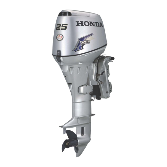
- Page 1 BF25Al3OA HONDA mmRinE Owner's Manual 2002 @ 2001 Honda Motor Co., Ltd. -All Rights Reserved...
- Page 2 The information and specifications included in this publication were in effect at the time of approval for printing. Honda Motor Co., Ltd. reserves the right, however, to discontinue or change specifications or design at any time without notice and without incurring any obligation whatever.
- Page 3 INTRODUCTION We suggest you read the warranty Congratulations on your selection of a Honda outboard motor. We are policy to fully understand its coverage and your responsibilities of certain you will be pleased with your ownership. The warranty policy is a...
- Page 4 INTRODUCTION A FEW WORDS ABOUT You will find important safety information in variety of forms, including: SAFETY Safety Labels on the outboard motor. Your safety and the safety of others are very important. And using this Safety Messages preceded by a safety alert symbol and one of outboard motor safely is an important three signal words, DANGER, WARNING, or CAUTION.
-
Page 5: Table Of Contents
CONTENTS ............... GearshiftIThrottle Control Lever OUTBOARD MOTOR SAFETY ............... Manual Choke Knob IMPORTANT SAFETY INFORMATION ..................Common Controls SAFETY LABEL LOCATIONS ..........Engine Cover Latch ..............Transom Angle Adjusting Rod CONTROLS AND FEATURES ..............Trim Tab CONTROL AND FEATURE .......... - Page 6 CONTENTS ....................STARTING THE ENGINE INSTALLATION ......................Type POWER REQUIREMENTS ..................R Type BOAT TRANSOM REQUIREMENTS ................. EMERGENCY STARTING INSTALLATION POSITION ....................ATTACHMENT STOPPING THE ENGINE ............Emergency Engine Stopping TRANSOM ANGLE ADJUSTMENT ................
- Page 7 CONTENTS ..................SERVICING YOUR OUTBOARD MOTOR STORAGE ..........52 THE IMPORTANCE OF MAINTENANCE STORAGE PREPARATION ................. MAINTENANCE SAFETY Cleaning and Flushing ................. TOOL KIT AND EMERGENCY STARTER Fuel ............................ Engine Oil ROPE ..............STORAGE PRECAUTIONS SCHEDULE MAINTENANCE ........
- Page 8 CONTENTS ..TAKING CARE OF UNEXPECTED PROBLEMS TECHNICAL AND CONSUMER INFORMATION ........ ELECTRICAL STARTER WILL NOT TECHNICAL INFORMATION ..................... OPERATE Serial Number Locations ........ENGINE WILL NOT START Carburetor Modification for High Altitude ............HARD STARTING OR STALLS AFTER Operation ............
-
Page 9: Outboard Motor Safety
INFORMATION It is the operator’s responsibility to Always wear a PFD (Personal provide the necessary safeguards Honda BF25A and BF30A outboard Flotation Device) while on the to protect people and property. motors are designed for use with boat. Know how to stop the engine boats that have a suitable quickly in case of emergency. - Page 10 OUTBOARD MOTOR SAFETY Refuel With Care Carbon Monoxide Hazard Exhaust gas contains poisonous Gasoline is extremely flammable, and gasoline vapor can explode. carbon monoxide. Avoid inhalation of exhaust gas. Never run the engine Refuel outdoors, in a well- ventilated area, with the engine in a closed garage or confined area.
-
Page 11: Safety Label Locations
5NINtlVM d33Y. AVUV NOUd S3ilYld 03111dS 3NllOSV3 Al313ldHO3 33139131 ilNO 3NIlOSVBI IN31131n35 TVNOILdO XNVL 3AOR311 HOU4 IVOQ 1104 ONlllli 3lPVWWVlJNI Xfl3d39NVd... -
Page 12: Controls And Features
CONTROLS AND FEATURES CONTROL AND FEATURE IDENTIFICATION CODES LRSA Electric Stater Refer to this chart for an explanation of the Type Codes used in this manual to identify control and feature applications. According to Shaft Length (Example) BF25AlBF30A are provided with the Short Shaft following types according to the shaft L: Long Shaft... -
Page 13: Component And Control Locations
CONTROLS AND FEATURES COMPONENT AND CONTROL LOCATIONS H Type (tiller handle) FUEL HOSE LEVEL DIPSTICK STARTER GRIP THROTTLE GRIP OIL/FILLERCAP /p""il starter type) INDICATOR PRESSURE LIGHT RSHIFT LEVER CHOKE KNOB DRAIN SCREW EXHAUST PORT STOP SWITCH LANYARD WASH PLUG \PROPELLER WATER INTAKE SPARE EMERGENCY... - Page 14 CONTROLS AND FEATURES R Type (remote control) OIL FILLER CAP OIL PRESSURE OVERHEATING TILT LEVER INDICATOR LIGHT LEVEL PLUG STOP SWITCH GEAR OIL EXHAUST PORT WATER INTAKE SWITCH CLIP DRAIN PLUG PROPELLER...
- Page 15 CONTROLS AND FEATURES Fuel Tank (optional equipment) FUEL GAUGE VENT KNOB FUEL TANK (standard equipment) FUEL HOSE CONNECTOR (female) PRIMING BULB...
-
Page 16: Controls
CONTROLS AND FEATURES CONTROLS The engine stop switch has controls Choke Knob for normal engine stopping and H Type (tiller handle) emergency engine stopping. Engine Stop Switch and Switch The switch clip must be inserted in the engine stop switch in order for the engine to start and run. -
Page 17: Throttle Grip
CONTROLS AND FEATURES Gearshift Lever Throttle Friction Knob Throttle Grip THROTTLE FRICTION KNOB THROTTLE GRIP THROTTLE OPENING INDICATOR RELEASE GEARSHIFT LEVER The gearshift lever is used to select F The throttle friction knob adjusts (forward), N (neutral), or R (reverse) resistance to throttle grip rotation. -
Page 18: Recoil Starter Grip
CONTROLS AND FEATURES Recoil Starter Grip (models Electric Starter Button (models R Type (remote control) equipped with recoil starter) equipped with electric starter) For panel-mount or top-mount remote control information, refer to (reverse) the instructions provided with the GEARSHIFT LEVER (neutral) remote control equipment. -
Page 19: Switch Clip And Emergency Stop Switch
CONTROLS AND FEATURES Switch Clip and Emergency Stop Turning the ignition switch key to the The switch clip must be inserted in Switch (side-mount type) START position operates the starter the emergency stop switch in order motor. The key automatically returns the engine to start and run. -
Page 20: Choke/Fast Idle Lever
CONTROLS AND FEATURES Choke/Fast Idle Lever Gearshift/Throttle Control Lever (side-mount type) (side-mount type) GEARSHIFTRHROTTLE N (neutral) CONTROL LEVER LOWEST POSITION RELEASE LEVER IDLE LEVER The control lever automatically locks itself in the N (neutral) position. To move the lever out the N (neutral) OPEN The choke/fast idle lever opens and... - Page 21 CONTROLS AND FEATURES The gearshifdthrottle control lever controls engine speed and selects (forward), (neutral), or (reverse) gears. GEARSHIFTD'HROTTLE CONTROL LEVER Moving the control lever 30" from (neutral) selects the gear, and further movement increases engine speed. N (neutral) A friction adjuster near the base of the control lever adjusts the operating the control lever (p.
-
Page 22: Manual Choke Knob
CONTROLS AND FEATURES Manual Choke Knob Common Controls Transom Angle Adjusting Rod Engine Cover Latch The transom angle adjusting rod limits the tilt angle of the outboard motor when fully lowered. COVER UNLA CHOKE KNOB A manual choke knob is provided on the right side of the motor which can TRANSOM ANGLE ADJUSTING ROD be used in the event the battery is... -
Page 23: Trim Tab
CONTROLS AND FEATURES Steering Friction Bolt Trim Tab Proper adjustment prevents the TIGHTENING BOLT outboard motor from being trimmed too low (p. TRIM TAB The steering friction bolt adjusts The trim tab compensates for “torque steer,” which is a reaction of steering resistance. -
Page 24: Tilt Lever
CONTROLS AND FEATURES Tilt Lever INSTRUMENTS INDICATORS Fuel Gauge Oil Pressure Indicator (R type) LEVER FUEL GAUGE The tilt lever enables the outboard A fuel gauge is built into the cap of motor to be raised for shallow water the portable fuel tank. operation, beaching, launching, or mooring. -
Page 25: Overheating Indicator
CONTROLS AND FEATURES Cooling System Indicator Overheating Indicator When the green light is lit, oil pressure is OK. type) If oil pressure becomes low, the green light will off, and the engine protection system will limit engine speed. Remote controls are also equipped with a buzzer that sounds when the green light goes off. -
Page 26: Other Features
CONTROLS AND FEATURES Portable Fuel Tank Anode OTHER FEATURES Overrev Limiter The engine is equipped with an overrev limiter to prevent the possibility of mechanical damage from excessive engine speed. The overrev limiter may be activated during operation, limiting engine speed, if the outboard motor is tilted excessively, or when ventilation occurs during a sharp turn. -
Page 27: Fuel Cap Vent Knob
CONTROLS AND FEATURES Fuel Priming Bulb Fuel Cap Vent Knob VENT KNOB OUTLET END INLET END (TANK) A priming bulb is built into the fuel The cap is provided with a vent knob hose that connects the fuel tank to the to seal the portable fuel tank for outboard motor. -
Page 28: Installation
Follow the installation inches below the bottom of the boat. instructions provided in this manual. Honda BF25A and BF3 OA outboarc With the boat in the water and loaded, motors can be installed on a boat the antiventilation plate should be... -
Page 29: Attachment
INSTALLATION ATTACHMENT If the outboard motor is installed too Attach the stem bracket to the boat transom by tightening the clamp low, the boat will squat and be hard to plane, it will tend to porpoise, and screws. high-speed stability will be reduced. Attach a rope from the boat to the the outboard motor is installed too hole in the stem bracket. -
Page 30: Transom Angle Adjustment
BATTERY For electric starter operation, use a Honda BF25A and BF30A outboard 12-volt battery with an ampere-hour motors produce a 12-volt, 6-ampere rating of at least 70 Ah. battery-charging current and are... - Page 31 INSTALLATION Plug and Receptacle Battery Terminals (models without electric starter) TERMINAL DC RECEPTACLE -& TO ACCESSORI: i I \ CHARGING CORD BLACK or GREEN Battery To prepare the outboard motor for Connect the positive battery cable connection to a battery, pull the cover to the positive (+) battery terminal, Minimum Requirements the DC receptacle, connect...
- Page 32 INSTALLATION pEiq Be careful to avoid connecting the battery in reverse polarity, as that will damage the battery-charging system i n the outboard motor.
-
Page 33: Before Operation
OFF position. Familiarize yourself with all laws Honda Marine dealer correct it, and regulations relating to boating before you operate the outboard and the use of outboard motors. - Page 34 BEFORE OPERATION Safety Inspection Maintenance Inspection 58). Look around the outboard motor Check the engine oil level (p. for signs of oil or gasoline leaks. Running the engine with a low oil level can cause engine damage. If you are using the portable fuel tank, make sure it is in good Check to be sure the propeller is undamaged, and the castle nut is...
-
Page 35: Operation
OPERATION BREAK-IN PROCEDURE Next 60 minutes: SAFE OPERATING PRECAUTIONS Run the engine up to a maximum of Break-in period: 10 hours 4,000 to 5,000 rpm, which is about To safely realize the full potential of of maximum throttle opening. this outboard motor, you need a Proper break-in operation allows the moving parts to wear in smoothly for complete understanding of its... -
Page 36: Transom Angle Adjustment
OPERATION TRANSOM ANGLE The transom angle adjusting rod ADJUSTMENT limits the tilt angle of the outboard motor when fully lowered. Do not allow water to enter the idle exhaust port or the engine can be Proper adjustment prevents the damaged. outboard motor from being trimmed too low (p. -
Page 37: Portable Fuel Tank
OPERATION PORTABLE FUEL TANK FUEL HOSE CONNECTIONS Secure the portable fuel tank in the boat, so it won’t move around and become damaged. FUEL HOSE CONNECTOR Before use, open the fuel tank vent by turning the vent knob at least 2 or 3 turns counterclockwise. -
Page 38: Fuel Priming
OPERATION STARTING THE ENGINE FUEL PRIMING The engine will not start or run, unless the clip is in the switch. Type (tiller handle) The emergency stop switch clip OUTLET END and lanyard system is a safety ENGINE STOP (MOTOR) device that will stop the engine you fall away from the controls while operating the boat. - Page 39 OPERATION GEARSHIFT LEVER POINTER THROTTLE GRIP KNOB CHOKE 3. To start a cold engine, pull the 4. Align the START position with 2. Check the position of the gearshift the pointer for starting the engine. choke knob to the CLOSED lever.
- Page 40 OPERATION Electric starter 6. If the choke knob was pulled to STARTER GRIP the CLOSED position to start the (electric starter model) Press the electric starter button and engine, gradually push it to the hold it there until the engine starts. OPEN position as the engine warms up.
-
Page 41: R Type
OPERATION The engine will not start or run, Type N (neutral) (remote control) unless the clip is in the switch. The emergency stop switch clip For panel-mount or top-mount and lanyard system is a safety remote control information, refer to device that will stop the engine if the instructions provided with the you fall away from the controls... - Page 42 OPERATION Using the electric starter f or more than 5 seconds at a time will overheat the starter motor and can FAST IDLE RANGE damage it. Turning the ignition switch key to the START position while the engine is running can damage the starter motor and lywheel.
-
Page 43: Emergency Starting
OPERATION EMERGENCY STARTING Before getting under way, allow CHOKEEAST IDLE LEVER the engine to warm up sufficiently to ensure good performance. If the battery is discharged, or the starter motor and the recoil starter are Above 41°F (5"C), warm up the inoperative, you can start the engine engine for 2 or 3 minutes. - Page 44 OPERATION WASHERS NEUTRAL START FLYWHEEL CABLE WASHERS RECOIL STARTER FLYWEEL COVER EMERGENCY STARTER ROPE ASSEMBLY 2. (Electric starter type) 3. Set the controls the same as for Pull the emergency starter rope Remove the four bolts and the four normal starting (see pages 35 slowly until resistance is felt, then washers then remove the flywheel 40 ).
- Page 45 (p. 22 Have your closest authorized overheating indicator (p. 22 Honda marine dealer check your Use extreme care when cooling system indicator (p. 23 ). installing the engine electrical system and correct the problem, so you can use the cover.
-
Page 46: Stopping The Engine
OPERATION STOPPING THE ENGINE Normal Engine Stopping Emergency Engine Stopping SWITCH CLIP THROTTLE GRIP (neutral) SWITCH CLIP To stop the engine in an emergency, pull the clip out of the engine or emergency stop switch by pulling the CONTR lanyard. LEVER We suggest that you stop the engine this way occasionally to verify that... - Page 47 OPERATION 2. Turn the ignition switch key to the OFF position or press the engine PUSH stop switch until the engine stops. 3. When the boat is not in use, remove and store the ignition key and the emergency stop switch clip and lanyard.
-
Page 48: Gearshifting And Throttle Operation
OPERATION GEARSHIFTING AND To shift gears, turn the throttle grip to THROTTLE OPERATION the SLOW position, then move the THROTTLE gearshift lever to select F (forward), H Type (tiller handle) N (neutral) or R (reverse) gears. The engine can be started with the gearshift lever in the (neutral) position only. -
Page 49: R Type
OPERATION R Types To shift gears, move the control lever (remote control) to select F (forward), N (neutral) and R (reverse) gears. Side-Mount Type The control lever cannot be moved from the (neutral) position unless the neutral release lever is squeezed. Moving the control lever beyond the gear selection range increases engine TO DECREASE... -
Page 50: Steering
OPERATION STEERING Type (remote control) H Type (tiller handle) STEERING Steer the boat in the same manner as TO DE an automobile. Steer by moving the tiller handle Use the steering friction lever to help opposite the direction you want the hold a steady course while cruising. -
Page 51: Cruising
OPERATION CRUISING Trim NOTICE Engine Speed Install the outboard motor at the best Excessive tridtilt angle during trim angle for stable cruising and operation can cause propeller For best fuel economy, limit the maximum power. ventilation, overheating, and water throttle opening to 80%. Use the pump damage. -
Page 52: Shallow Water Operations
OPERATION If steering effort is not equal in both SHALLOW WATER To tilt the outboard motor, move the OPERATION directions, adjust the trim tab to tilt lever to the TILT position, then compensate for "torque steer," raise the outboard motor to the 30"... -
Page 53: Mooring, Beaching, Launching
OPERATION MOORING, BEACHING, p E i G - 1 ENGINE COVER GRIP LAUNCHING An excessive tilt angle during operation can cause propeller ventilation, overheating, and ,water pump damage. 75" (when mooring) TILT LEVER To raise the outboard motor out of To return the outboard motor to the the water while the boat is moored, or normal operating position, move the... -
Page 54: Servicing Your Outboard Motor
Honda parts or their equivalents for professionals and are normally repair and replacement. performed by a Honda technician or Improperly maintaining other qualified mechanic. -
Page 55: Maintenance Safety
SERVICING YOUR OUTBOARD MOTOR Safety Precautions Read the instructions before you MAINTENANCE SAFETY begin, and make sure you have the Make sure the engine is off before tools and skills required. Some of the most important safety you begin any maintenance or precautions follow. -
Page 56: Tool Kit And Emergency Starter Rope
SERVICING YOUR OUTBOARD MOTOR TOOL KIT AND EMERGENCY STARTER ROPE 12 mm WRENCH SOCKET WRENCH WRENCH EMERGENCY STARTER ROPE FLAT SCREWDRIVER PLIERS The following tools are supplied with the outboard motor for simple > maintenance procedures and PHILLIPS SCREWDRIVER TOOL BAG emergency repairs. -
Page 57: Schedule Maintenance
Check for water Emission-related items Lubricate more frequently when used in salt water. These items should be serviced by an authorized Honda marine dealer, unless have the proper tools and are mechanically proficient. Refer to the Honda shop manual for service procedures. - Page 58 Emission-related items. Lubricate more frequently when used in salt water. These items should be serviced by an authorized Honda marine dealer, unless you have the proper tools are mechanically proficient. Refer to the Honda shop manual for service procedures.
-
Page 59: Trim Tab Adjustment
SERVICING YOUR OUTBOARD MOTOR TRIM TAB ADJUSTMENT I“ The trim tab compensates for “torque steer” which is a reaction of TIGHTENING the outboard motor to propeller TIGHTENING BOLT rotation. If uncompensated, torque steer would make the outboard motor tend to turn to one side. -
Page 60: Engine Cover Removal And Installation
SERVICING YOUR OUTBOARD MOTOR ENGINE COVER REMOVAL Engine Oil Level Check OIL FILLER CAP AND INSTALLATION Check the engine oil level with the engine stopped and the outboard motor in the vertical position. Unlatch and remove the engine cover. Remove the dipstick and wipe it clean. -
Page 61: Engine Oil Change 78
SERVICING YOUR OUTBOARD MOTOR Engine Oil Change p i i q SEALING WASHER Improper disposal of engine oil An engine oil evacuatiordfilling can be harmful to the environment. device may be used to remove/add If you change your own oil, please the engine oil. -
Page 62: Engine Oil Recommendations
The SAE oil viscosity and service classification are in the API label on Oil is a major factor affecting the oil container. Honda recommends Check the gear oil level with the performance and service life. Use that you use API SERVICE category engine stopped and the outboard SG, or SH oil with the “starburst”... -
Page 63: Gear Oil Change
Honda Marine dealer. 1. Place a suitable container below the oil drain hole to catch the used oil, then remove the oil level plug and oil drain plug. - Page 64 SERVICING YOUR OUTBOARD MOTOR OIL LEVEL PLUG TORQUE: 2.6 Ibf-f? (3.5 N-m 0.36 kgf-m) oz (30 Avoid losing more than 1 fl cm3) while reinstalling the drain Plug* OIL DRAIN PLUG TORQUE: 2.6 Ibfmft (3.5 N.m kgfmm) ,0.36 GEAR OIL BOTTLE 4.
-
Page 65: Lubrication Points
20 hours or a month after the date of purchase for initial 100 hours or 6 months. NOTICE Apply anticorrosion oil to pivot surfaces where grease cannot penetrate. Apply Honda Marine Corrosion Inhibitor (or equivalent) to all areas under the engine cover except the belts. - Page 66 SERVICING YOUR OUTBOARD MOTOR ADJUSTING ROD...
-
Page 67: Spark Plug Service
SERVICING YOUR OUTBOARD MOTOR Spark Plug Service RECOMMENDED SPARK PLUGS: 0.70 mm) (0.60 DR7EA (NGK) X22ESR-U (DENSO) Incorrect spark plugs can cause engine damage. 1. Unlatch and remove the engine cover (p. 58 ). SPARK PLUG SPARK PLUG WRENCH CAPS 2. - Page 68 SERVICING YOUR OUTBOARD MOTOR After each spark plug seats, tighten with a spark plug wrench supplied in the tool kit to compress the sealing washer. If reinstalling the used spark plugs, tighten 1/4 turn after the spark plugs seat. If reinstalling new spark plugs, tighten 1/2 turn after the spark plugs seat.
-
Page 69: Refueling
SERVICING YOUR OUTBOARD MOTOR REFUELING Gasoline is highly Portable Fuel Tank flammable and explosive. (optional equipment) You can be burned or FUEL TANK CAPACITY: seriously injured when 6.61 US gal (25.0 !2,5.50 handling fuel. gal) FUEL GAUGE Stop the engine and keep Check the fuel gauge and refill the heat, sparks, and flame tank when necessary. -
Page 70: Fuel Recommendations
If spark knock or pinging occurs at a hard starting. prevent engine steady engine speed, under normal malfunction, inspect the filter and load, change brands of gasoline. If replace when necessary. spark knock or pinging persists, see an authorized Honda marine dealer. - Page 71 SERVICING YOUR OUTBOARD MOTOR Disconnect the fuel hose from the outboard motor, and place clamps on the fuel hoses on each side of the filter to prevent fuel leakage when the fuel hoses are disconnected. FUEL HOSES FUEL FILTER ENGINE COVER LATCHS 2.
-
Page 72: Portable Fuel Tank And Filter Cleaning
SERVICING YOUR OUTBOARD MOTOR Fuel Tank Filter Portable Fuel Tank Filter Cleaning TANK FILTER JOINT TANK FILTER JOINT Fuel Tank (Fuel Connector) (Fuel Connector) FUEL H9SE FILTER ARROW 1. Unscrew the fuel hose connector (Fuel Flow Direction) by turning it counterclockwise, then remove the fuel hose Install the new filter on the fuel connector and fuel filter from the... -
Page 73: Recoil Starter Rope Inspection
SERVICING YOUR OUTBOARD MOTOR Recoil Starter Rope Inspection Anode Replacement Painting or coating the anode will defeat its purpose and will lead to rust and corrosion damage to the outboard motor. The anode must be exposed to the water in order to protect the outboard motor. -
Page 74: Propeller Replacement
Install the thrust washer with the are working with the propeller. grooved side toward the gear case. The propeller blades may have sharp Use a genuine Honda cotter pin edges, wear heavy gloves to the pin ends as shown. protect your hands. -
Page 75: Storage
STORAGE Flushing With the Honda STORAGE PREPARATION Hose Garden Adapter Proper storage preparation is essential for keeping your outboard motor troublefree and looking good. The following steps will help to keep rust and corrosion from impairing your outboard motor’s function and... - Page 76 STORAGE 4. Move the gearshift lever or control TAPE lever to the N (neutral) position. Flush the outboard motor in the neutral position only. Turn on the fresh water supply to the garden hose adapter. pciq Running the outboard motor without sufficient cooling water will damage the water pump and overheat the COOLING SYSTEM INDICATOR...
-
Page 77: Fuel
STORAGE Fuel Warranty The Distributor’s Limited does not cover fuel system damage Gasoline will oxidize and deteriorate or engine performance problems Gasoline is highly in storage. Old gasoline will cause resulting from neglected storage flammable and explosive. hard starting, and it leaves gum preparation. -
Page 78: Engine Oil
STORAGE Engine Oil 1 CARBURETOR 1. Change the engine oil and the oil DRAIN SCREW filter (p. 59 2. Remove the spark (p. 65 plugs 2 CARBURETOR and remove the clip from the DRAIN SCREW engine or emergency stop switch. 3. -
Page 79: Storage Precautions
STORAGE STORAGE PRECAUTIONS If the outboard motor will be Cover the outboard motor to keep out dust. Do not use sheet plastic as a removed from the boat for storage, Select a well-ventilated storage area. we recommend storing it vertically dust cover. -
Page 80: Transporting
TRANSPORTING WITH OUTBOARD MOTOR WITH OUTBOARD MOTOR INSTALLED ON BOAT REMOVED FROM BOAT When trailering a boat with the Secure the outboard motor in either outboard motor attached, leave the the vertical or horizontal position engine in the normal running position, shown on p. -
Page 81: Taking Care Of Unexpected Problems
Replace or repair faulty 3. Use emergency starting Starter malfunction, switch components as necessary. procedure (p. 41 then take malfunction, or electrical problem in the starting circuit. outboard motor to an authorized Honda Marine dealer, or refer to the shop manual. -
Page 82: Engine Will Not Start
TAKING CARE OF UNEXPECTED PROBLEMS ENGINE WILL NOT START Possible Cause Correction 1. Check emergency stop switch Clip not inserted in stop switch. Insert clip in stop switch. clip. 2. Check control positions. Gearshift lever or control lever not Shift to neutral (p. 15 ). in neutral position. - Page 83 Carburetor malfunction, fuel pump Replace or repair faulty 5. Take outboard motor to an components as necessary. failure, ignition malfunction, stuck authorized Honda Marine dealer, valves, etc. or refer to the shop manual.
-
Page 84: Hard Starting Or Stalls After Starting
TAKING CARE OF UNEXPECTED PROBLEMS HARD STARTING OR STALLS Possible Cause Correction AFTER STARTING 1 . Check control positions. Pull choke knob to CLOSED Choke OPEN (tiller-handle type). position, unless engine is warm (p. Throttle grip not in START Turn throttle grip to START (p. position (tiller-handle type). -
Page 85: Engine Overheats
>. (P. 65 Carburetor malfunction, fuel pump Replace or repair faulty 4. Take outboard motor to an failure, ignition malfunction, etc. authorized Honda Marine dealer, components as necessary. or refer to the shop manual. Possible Cause Correction ENGINE OVERHEATS Clean water intake screens. -
Page 86: Battery Will Not Charge And Electric Starter Will Not Operate
TAKING CARE OF UNEXPECTED PROBLEMS BATTERY WILL NOT 3. Remove and inspect the fuse. If FUSE CASE CHARGE AND ELECTRIC fuse is burnt out, install a STARTER WILL NOT replacement fuse of the specified OPERATE rating. The outboard motor is supplied with spare fuse in the fuse holder. -
Page 87: Oil Pressure Indicator Light Goes Off And Engine Speed Is Limited
Low oil pressure may be the result of and have the outboard motor a low engine oil level, or there may inspected by an authorized Honda be a problem with the engine marine dealer. lubrication system. -
Page 88: Overheating Indicator Light Comes On And Engine Speed Is Limited
If overheating activates the engine and have the outboard motor red indicator light comes on. protection system, idle the engine in inspected by an authorized Honda neutral, and check the cooling system marine dealer. indicator. -
Page 89: Submerged Motor
If there is a Honda marine dearship nearby, take the motor to the dealer Remove the spark plugs (p. 65 immediately. If you are far from a... - Page 90 8. As soon as possible, take the outboard motor to an authorized 6. Reinstall the spark plugs, and put Honda Marine dealer for the emergency stop switch clip inspection and service. into the switch.
-
Page 91: Technical And Consumer Information
TECHNICAL AND CONSUMER INFORMATION TECHNICAL INFORMATION STARTER MOTOR RIGHT STERN BRACKET Serial Number Locations Record the product identification number and engine serial numbers in the space provided on this page. You will need these numbers when ordering parts, and when making technical or warranty inquiries (p. -
Page 92: Carburetor Modification For High Altitude Operation
5,000 meters) with modified carburetors altitudes above feet (1,500 may cause the engine to overheat meters), have an authorized Honda marine dealer perform this carburetor and result in serious engine damage. For use at low altitudes, have an modification. authorized Honda Marine dealer return the carburetors to original factory specifications. -
Page 93: Oxygenated Fuels
TECHNICAL AND CONSUMER INFORMATION Oxygenated Fuels damage metal, rubber, and plastic The following are the EPA-approved parts of your fuel system. percentages of oxygenates: Some conventional gasolines are ETHANOL: ethyl or grain alcohol; If you notice any undesirable being blended with alcohol or an 10% by volume. -
Page 94: Emission Control System Information
Honda engine within the emission Alterations that would cause the to sunlight. Carbon monoxide does standards. engine to operate outside its design not react in the same way, but it is toxic. - Page 95 Emissions the part will not adversely affect The emission control systems on emission performance. The your Honda engine were designed, If you are aware of any of the manufacturer or rebuilder of the part built, and certified to conform with...
-
Page 96: Star Label
TECHNICAL AND CONSUMER INFORMATION SUar Label The Star Label means Cleaner Marine Engine This engine has been certified as a: Star label was applied to this outboard motor in accordance with the requirements of the California Air Resources Board. The Symbol for Cleaner Marine Engines: Cleaner Air and Water for healthier lifestyle and environment. - Page 97 TECHNICAL AND CONSUMER INFORMATION Three Stars One Star Two Stars Ultra Low Emission Low Emission Very Low Emission The three-star label identifies engines The one-star label identifies engines The two-star label identifies engines that meet the Air Resources Board’s that meet the Air Resources Board’s that meet the Air Resources Board’s 2008 exhaust emission standards.
-
Page 98: Specifications
0.02 mrn See shop Exhaust: 0.20 b 0.02 manual (cold) Other specifications No other adjustment needed qt (1.6 Q , 1.4 Imp qt) Honda outboards are power rated in accordance with N " A procedures and using the ICOMIA standard 28/23. - Page 99 0.02 m m See shop Gear case:API standard (GL4/5) Exhaust: 0.20 0.02 rnrn manual (cold) Other specifications No other adiustment is needed 1.7USqt(1.6Q,1.4Impqt) Gear case: Honda outboards are power rated in accordance with NMMA procedures and using the ICOMIA standard 28/23.
- Page 100 0.20 f 0.02 mm manual Exhaust: (cold) Other specifications No other adiustment is needed SAE 1 OW-30 Gear case:API standard (GL4/5) SAE 90 (1.6 1.4 Imp qt) Honda outboards are power rated in accordance with NMMA procedures and using the ICOMIA standard 28/23.
- Page 101 1.7USqt(1.6Q,1.4Impqt) Exhaust: 0.20 0.02 m m manual (cold) Gear case: No other adjustment is needed Other specifications 0.31 US (0.29 Q ,0.26 Imp qt) Honda outboards are power rated in accordance with NMMA procedures and using the ICOMIA standard 28/23.
-
Page 102: Consumer Information
Name of the dealer who sold the outboard motor. You may order them please discuss it with the dealership’s outboard motor to you from your Honda marine dealer. management. The Service Manager Shop Manual or General Manager can help. Almost Name and address of the dealer all problems are solved in this way. -
Page 103: Wiring Diagrams
WIRING DIAGRAM IQNlTlON PULSE GENERATOR TILLER HANDLE TYPE (with recoil starter) ........ - Page 104 WIRING DIAGRAM R”” I I I I I IIIII...
- Page 105 WIRING DIAGRAM CONTROL REMOTE TYPE IGNITION PULSEGENERATOR R W E U P " W \...
-
Page 106: Index
INDEX ..........................Electric Starter Button Anode ......................EMERGENCY STARTING Replacement ......? ..Emission Control System Information ARE YOU READY TO GET UNDER WAY ............Engine ATTACHMENT Cover ....................... Latch BATTERY CONNECTIONS ....REMOVAL AND INSTALLATION BATTERY WILL NOT CHARGE AND ELECTRIC STARTER WILL NOT .............. - Page 107 INDEX ............... Fuel Ignition Switch ................Cap Vent Knob IMPORTANT SAFETY INFORMATION ..............................Gauge INDEX ......................HOSE CONNECTIONS INDICATORS ..........................PRIMING INSTALLATION ..................... Priming Bulb INSTALLATION POSITION ................Pump Filter Inspection and Replacement INSTRUMENTS ...........
- Page 108 INDEX ................SAFE OPERATING PRECAUTIONS Oil Pressure Indicator ........SAFETY LABEL LOCATIONS OIL PRESSURE INDICATOR LIGHT GOES ............... Serial Number Locations OFF AND ENGINE SPEED IS LIMITED ................SERVICING YOUR OUTBOARD MOTOR OPERATION .................. SHALLOW WATER OPERATION OTHER FEATURES ........
- Page 109 INDEX ............. WIRING DIAGRAMS TAKING CARE UNEXPECTED PROBLEMS TECHNICAL AND CONSUMER INFORMATION ........TECHNICAL INFORMATION ....THE IMPORTANCE OF MAINTENANCE ........... Throttle Friction Knob ..............Throttle Grip ................ Tilt Lever TOOL KIT AND EMERGENCY STARTER ROPE ........Transom Angle Adjusting Rod ......
- Page 110 HONDA The Power of Dreams @ @ (HC) 1000.2001.05 31ZV7615 Printed in Japan 00x31-ZV7-6150...
Need help?
Do you have a question about the Marine BF25A and is the answer not in the manual?
Questions and answers